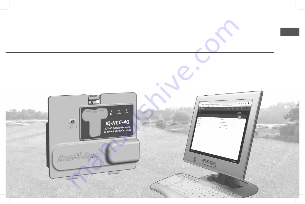
background image

ENG

IQ

TM

 Network Communication Cartridge (IQ-NCC)

Installation and User Manual for the IQ

TM

 Central Control System

Rain+Birdt

638085-02_20JA20_IQ-NCC user manual.indd   1

638085-02_20JA20_IQ-NCC user manual.indd   1

1/20/2020   11:20:29 AM

1/20/2020   11:20:29 AM

Summary of Contents for IQ-NCC

Page 1: ...tion Cartridge IQ NCC Installation and User Manual for the IQ TM Central Control System Rain Birdt 638085 02_20JA20_IQ NCC user manual indd 1 638085 02_20JA20_IQ NCC user manual indd 1 1 20 2020 11 20 29 AM 1 20 2020 11 20 29 AM ...

Page 2: ... injury CCAUTION Indicates a hazardous situation that if not avoided could result in minor or moderate injury NOTICE Indicates information considered important but not haz ard related e g messages relating to property damage SAFETY INSTRUCTIONS Specific safety related instructions or procedures are described Symbols User Operation a NUMBERS define a series of steps for the user to follow in order ...

Page 3: ...ptions 8 Figure 2 Installation Overview 9 Box Contents 10 Figure 3 Box Contents 11 Cartridge Installation 12 Access Controller Cabinet 12 Remove the Communication Cable Knock out 13 Install an External Antenna for LXMM 14 Install the Cartridge 16 Figure 4 Installation Cable Options 17 Complete Cable Connections 19 Internal Antenna Installation 22 IQ NCC Configuration 24 Direct Satellite Setup Wiza...

Page 4: ...40 Connection Modules 40 Connection Module Options 40 Base Module 40 Flow Smart Module 40 IQ Connection Module 41 IQ Flow Smart Connection Module 41 Connection Module Installation 42 Connect IQ CM Grounding Wire 44 SIM Card Installation 45 Regulatory Information 46 EMC Requirements for the United States 46 638085 02_20JA20_IQ NCC user manual indd 4 638085 02_20JA20_IQ NCC user manual indd 4 1 20 2...

Page 5: ...ain Bird ESP LXME ESP LXMEF ESP LXD ESP LXIVM and ESP LXIVM Pro controllers normally operate as stand alone irrigation controllers but can be upgraded to become field components of the IQ Central Control System with the installation of an IQ Network Communications Cartridge IQ TM Central Control System The IQ Central Control System provides remote communi cation capability for programming and moni...

Page 6: ... Satellites communicate with the Server Satellite or to other Client Satellites over the IQNet using IQ radio modems or a high speed PE Cable communication connections Products Covered in this Manual This manual describes the installation of the following Rain Bird IQ products Ethernet Network Communication Cartridge IQNCCEN 4G Cellular Network Communication Cartridge IQ4G USA and IQ4G RS 232 Netw...

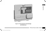
Page 7: ...ation Cartridge Introduction ENG Figure 1 IQ Network Communication Cartridge IQ NCC 4G shown 638085 02_20JA20_IQ NCC user manual indd 7 638085 02_20JA20_IQ NCC user manual indd 7 1 20 2020 11 20 30 AM 1 20 2020 11 20 30 AM ...

Page 8: ...ection Module CM Port Cable The Connection Module CM Port Straight Cable provides the connection between the IQ NCC Cartridge and the Con nection Module Radio Modem Cable A radio modem can also be connected to the IQ NCC Car tridge using the Y Cable to provide wireless radio commu nication between Server and Client Satellites on the IQNet Configuration Options Before beginning installation the fol...

Page 9: ... Connection Module CM Cable CM Y Cable shown a To IQNet Radio Modem b To Connection Module d IQ Port Cable or Antenna e Ground Wire f IQNet PE Communication Cable to other Satellites g Connection Module FSCM LXME shown c d e f c g a b b b a a 638085 02_20JA20_IQ NCC user manual indd 9 638085 02_20JA20_IQ NCC user manual indd 9 1 20 2020 11 20 30 AM 1 20 2020 11 20 30 AM ...

Page 10: ...Cartridge IQNCCRS RS 232 Cartridge 2 Cartridge to Connection Module and or Radio cables CM Y Cable IQ Radio and Connection Module CM Straight Cable Connection Module 3 IQ Communication Cables and Antennas Ethernet Cable IQNCCEN only Cellular Internal Antenna IQ4G USA and IQ4G only External Modem Cable IQNCCRS only IQ Null Modem Cable NCC Configurator Configuration 4 Installation Manual Quick Refer...

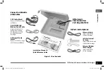
Page 11: ... IQ NCC Cartridge to CM Connection Module Ethernet Cable Ships with IQNCCEN Ethernet Cartridge Cellular Internal Antenna Ships with IQ4G USA and IQ4G Cellular Cartridge External Modem Cable beige Ships with IQNCCRS RS 232 Cartridge Installation Manual Quick Reference Guide IQ Network Communication Cartridge IQ NCC Connection Module CM Cables IQ Port Cable Options 638085 02_20JA20_IQ NCC user manua...

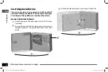
Page 12: ...ces explained separately Access Controller Cabinet a Unlock and open the outer door of the ESP LX Series Controller b To open the controller front panel grasp the crescent shaped handle on the right hand side of the front panel a b c Pull the handle towards you and swing it to the left c 638085 02_20JA20_IQ NCC user manual indd 12 638085 02_20JA20_IQ NCC user manual indd 12 1 20 2020 11 20 30 AM 1...

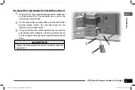
Page 13: ...talled for IQNet communication locate the rear knock out for the IQNet communication cable c Using a screwdriver or other pointed tool center the point of tool on the dimple in the center of the knock out then punch through and remove the cable knock out s CCAUTION Always wear eye protection when using tools or power equipment a b c 638085 02_20JA20_IQ NCC user manual indd 13 638085 02_20JA20_IQ N...

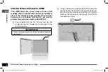
Page 14: ...ing a power drill and 5 8 16 mm drill bit drill a hole through the dimple on the top right of the LXMM metal case CCAUTION Always wear eye protection when using tools or power equipment a b Using a screwdriver or other pointed tool center the point of tool on the dimple in the center of the knock out then punch through and remove the antenna knock out hole located on the top right of the ESP LX co...

Page 15: ...he hole and secure from the inside as shown using the washers and nut provided d CWARNING To comply with FCC RF safety exposure limits the antenna used for this transmitter must be installed to provide a separation distance of at least 20 cm from all persons and must not be located or operating in con junction with any other antenna or transmitter 638085 02_20JA20_IQ NCC user manual indd 15 638085...

Page 16: ...e Y cable plugs directly into the radio modem see user manual that comes with radio modem for installation and con figuration instructions If the satellite is a Server or Client that will use a wired connection IQNet PE Communication Cable to com municate with other satellites install the straight cable If the satellite is a Server or Client that will use a radio module for wireless communications...

Page 17: ...odem Cable beige IQ Network Communication Cartridge IQ NCC CM Y Cable black CM Straight Cable black Align Arrows on Cable and Housing for Correct Fitting CM Port Cables IQ Port Cables Figure 4 Installation Cable Options 638085 02_20JA20_IQ NCC user manual indd 17 638085 02_20JA20_IQ NCC user manual indd 17 1 20 2020 11 20 31 AM 1 20 2020 11 20 31 AM ...

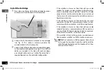
Page 18: ...on cable to the card edge connector located at the top left of the cartridge bay NOTICE Ensure that the RED edge of the ribbon cable is towards the LEFT side of the connector d e Orient the cartridge so that the two bottom hinges fit into the hinge openings at the bottom of the cartridge bay Then gently swing the IQ NCC up into place snapping the top latch e 638085 02_20JA20_IQ NCC user manual ind...

Page 19: ...n ENG Complete Cable Connections a Route all cables from the cartridge through the channel in back of the front panel a 638085 02_20JA20_IQ NCC user manual indd 19 638085 02_20JA20_IQ NCC user manual indd 19 1 20 2020 11 20 31 AM 1 20 2020 11 20 31 AM ...

Page 20: ...dules section of the Appendix for details If no wired connection is required retain the base module that was shipped with the controller The ESP LXD ESP LXIVM and ESP LXIVM Pro controllers do not ship with a base module d If a CM Port cable Y cable or straight is installed connect the keyed mating connector to the CM Connection Module as shown B NOTE The Y cable may be used for a radio modem wirel...

Page 21: ...alled cables inside the satellite do not contact the transformer directly as heat from the transformer may cause damage to a cable g Connect the metal shield of the PE Cable to the orange ground terminal at one end of the PE Cable only 638085 02_20JA20_IQ NCC user manual indd 21 638085 02_20JA20_IQ NCC user manual indd 21 1 20 2020 11 20 31 AM 1 20 2020 11 20 31 AM ...

Page 22: ...se without pinching the antenna cable CWARNING To comply with FCC RF safety exposure limits the antenna used for this transmitter must be installed to provide a separation distance of at least 20 cm from all persons and must not be located or operating in con junction with any other antenna or transmitter NOTICE Take special care the first time when placing the antenna Once installed it cannot be ...

Page 23: ...This page intentionally left blank 638085 02_20JA20_IQ NCC user manual indd 23 638085 02_20JA20_IQ NCC user manual indd 23 1 20 2020 11 20 31 AM 1 20 2020 11 20 31 AM ...

Page 24: ...LX IVM Turn the controller dial to Advanced Settings and choose Configure Cartridge a The IQ Settings main menu is displayed Use the UP or DOWN arrows to select Setup Wizard press Next b The Setup Satellite Type screen is displayed Use or to select Direct press Next c The Setup Satellite Address screen is displayed Direct Satellitesalwayshaveanaddress of 001 press Next d The Setup Satellite IQ Por...

Page 25: ... option either 4G GPRS Cellular or Ethernet modem e The following message will be displayed Press Dismiss to exit screen The Satellite is now ready to be con figured by the NCC Configurator software only required for IQNCC EN Ethernet Cartridge configura tion 638085 02_20JA20_IQ NCC user manual indd 25 638085 02_20JA20_IQ NCC user manual indd 25 1 20 2020 11 20 32 AM 1 20 2020 11 20 32 AM ...

Page 26: ...tridge a The IQ Settings main menu is displayed Use the UP or DOWN arrows to select Setup Wizard press Next b The Setup Satellite Type screen is displayed Use or to select Server press Next c The Setup Satellite Address screen is displayed Server Satellitesalwayshaveanaddress of 001 press Next d The Setup Satellite IQ Port screen is displayed press Next 638085 02_20JA20_IQ NCC user manual indd 26 ...

Page 27: ...pending on the cartridge that is installed e The Setup Satellite Radio Port screen is displayed Use or to select a radio port option No Radio Installed Radio Installed press Next B NOTE If an IQ FSCM LXME or an IQ CM LXD connection mod ule is installed for wired com munications with other satel lites choose Module Installed g The following message will be displayed Press Dismiss to exit screen The...

Page 28: ...OWN arrows to select Setup Wizard press Next b The Setup Satellite Type screen is displayed Use or to select Client press Next c The Setup Satellite Address screen is displayed Use or to select a unique address from 002 256 for this satellite press and HOLD buttons to accelerate settings press Next d The Setup Satellite Radio Port screen is displayed Use or to select a radio port option No Radio I...

Page 29: ...s choose Module Installed f TheSetup CMPortTermination screen is displayed Use or to select a CM Port Termination option On or Off B NOTE CM Port termination is only required if this satellite is at the end of an IQNet PE Com munication Cable path If you are not sure consult with the system designer NCC Configurator Software The NCC Configurator Software is used to configure the network con nectio...

Page 30: ...without affecting configuration settings LED Indicators The three LED lights on the front of each cartridge indicate the status of each communication port on any satellite con troller The meaning of each LED state is provided in the fol lowing tables Turn the ESP LX Controller dial to IQ Settings and select Sta tus for text version of the communication ports status Reset Button LED Lights IQ Netwo...

Page 31: ...llow Receiving data but not authenticated Receiving data but not authenticated Connecting with IQ but has not completed authentication Solid green Authenticated with IQ but no data is being sent received Authenticated with IQ but no data is being sent received Authenticated with IQ but no data is being sent received Blinking green Authenticated with IQ and data is being sent received Authenticated...

Page 32: ...will continue to flash green as it searches for Client Satellites LED State Radio Modem Status Dark Port disabled also dark if configured as Client or No Radio Installed option selected in Setup Wizard Solid Red N A Blinking Red No radio modem detected Solid Yellow N A Blinking Yellow N A Solid green Radio modem detected but no data is being sent received Blinking green Radio modem detected data i...

Page 33: ... Client Satellite Direct Satellite Controllers Ethernet To display the status of Direct Satel lites IQNCCEN cartridge installed For LXD and LXME Turn the controller dial to ETM IQ SETTINGS For LX IVM Turn the controller dial to Advanced Settings and choose Configure Cartridge a The IQ Settings main menu is displayed Use the UP or DOWN arrows to select Status press Next b The Satellite Status scree...

Page 34: ...ridge a The IQ Settings main menu is displayed Use the UP or DOWN arrows to select Status press Next b The Satellite Status screen is displayed Current status of IQ Radio and CM ports are shown Press Signal to display 4G signal strength c The Signal Strength screen is displayed The signal strength between the satellite and the 4G or LAN network is indicated on a scale from 1 10 638085 02_20JA20_IQ...

Page 35: ...he Satellite Status screen is displayed Current status of IQ Radio and CM ports are shown Press Ping to check the communication status with selected Clients c The IQNet Ping screen is displayed Use the and buttons to select any Client address Press Ping to check the communication status The LCD will display Response Yes if the ping is successful or No for an unsuccessful ping The amount of time un...

Page 36: ...N arrows to select Status press Next b The Satellite Status screen is displayed Current status of IQ Radio and CM ports are shown Press Signal to display 4G Cellular signal strength c The Signal Strength screen is displayed The signal strength between the satellite and the 4G or LAN network is indicated on a scale from 1 10 d The Satellite Status screen is displayed Press Ping to check the communi...

Page 37: ...display the status of Client Satel lites with any cartridge installed For LXD and LXME Turn the controller dial to ETM IQ SETTINGS For LX IVM Turn the controller dial to Advanced Settings and choose Configure Cartridge a The IQ Settings main menu is displayed Use the UP or DOWN arrows to select Status press Next b The Satellite Status screen is displayed Current status of IQ Radio and CM ports are...

Page 38: ...hoose Configure Cartridge a The IQ Settings main menu is displayed Use the UP or DOWN arrows to select IQNet Alarms press Next b If there are no alarms the following screen is displayed c If there is a communication failure between the Server Satellite and Client Satellites the IQNet Alarm screen will be displayed on the Server Satellite Use the UP or DOWN arrows to view other alarms 638085 02_20J...

Page 39: ...tellite the IQNet Alarm screen will be displayed on the Client Satellite Use the UP or DOWN arrows to view other alarms e On either IQNet Alarm screen press Clear to clear all alarms Press Yes to confirm 638085 02_20JA20_IQ NCC user manual indd 39 638085 02_20JA20_IQ NCC user manual indd 39 1 20 2020 11 20 34 AM 1 20 2020 11 20 34 AM ...

Page 40: ... ESP LX Series Controller The type of connection module that is required for installation of an IQ Network Communication Cartridge depends on the type of controller and on the type of communication required with other satellites wired or wireless Base Module The BM LXME Base Module is the default module that comes with an ESP LXME controller This module can be used with an IQ NCC when wired commun...

Page 41: ...t ellite to make the connection IQ Flow Smart Connection Module If wired communications IQNet PE Communication Cable is required between an ESP LXME satellite and other satellites an IQ FSCM LXME Connection Module must be installed in the ESP LXME satellite to make the connection B NOTE See the ESP LXME Con troller Manual for instructions on configuring the Flow Smart Module 638085 02_20JA20_IQ NC...

Page 42: ...XIVM or ESP LXIVM Pro does not ship with a base module Remove the black plastic cover on the backplane in slot 0 to reveal the pins on the connector a b Orient the connector on the bottom of the IQ FSCM LXME or IQ CM LXD module with the connection socket on the satellite backplane c Carefully fasten the module onto the satellite backplane pressing firmly until it snaps into place b 638085 02_20JA2...

Page 43: ... ENG d Connect the green and yellow ground wire to the grounding post on the left side of the satellite backplane d 638085 02_20JA20_IQ NCC user manual indd 43 638085 02_20JA20_IQ NCC user manual indd 43 1 20 2020 11 20 34 AM 1 20 2020 11 20 34 AM ...

Page 44: ... electrical ground rod or ground plate b Route the grounding wire through the knock out on the bottom of the controller c Attach the grounding wire to the CM module GND terminal as shown CWARNING Failure to ensure proper grounding of the connection module could result in risk of electric shock or other hazard to persons as well as possible equipment dam age and malfunction aTo Earth ground b c 638...

Page 45: ...ained from AT T or another GSM 4G service provider and must be pur chased separately Follow these steps to install a SIM card in the IQ4G a On the front of the IQ4G remove the T shaped access plate by pressing down on the tab a b Orient the SIM card to match the image of the SIM card as displayed molded on the cartridge with the cut corner on top and to left as shown c Install the SIM card in the ...

Page 46: ...that to which the receiver is connected Consult the dealer or an experienced radio TV techni cian for help This device complies with 47 CFR FCC Part 15 rules Opera tion of this device is subject to the following conditions 1 This device may not cause harmful interference and 2 This device must accept any interference that may cause undesired operation This product was FCC certified under test cond...

Page 47: ...nterna tional Mobile Equipment Identity number This IEMI num ber is printed on the label on the backside of the modem cartridge 638085 02_20JA20_IQ NCC user manual indd 47 638085 02_20JA20_IQ NCC user manual indd 47 1 20 2020 11 20 35 AM 1 20 2020 11 20 35 AM ...

Page 48: ...n 6991 East Southpoint Road Tucson AZ 85756 USA Tel 520 741 6100 Rain Bird Corporation 970 W Sierra Madre Ave Azusa CA 91702 USA Tel 626 812 3400 Rain Bird International 1000 W Sierra Madre Ave Azusa CA 91702 USA Tel 1 626 963 9311 Technical Services for U S and Canada only 1 800 RAINBIRD 1 800 247 3782 www rainbird com 638085 02_20JA20_IQ NCC user manual indd 1 638085 02_20JA20_IQ NCC user manual...

Reviews: