


Summary of Contents for F6
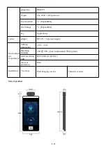
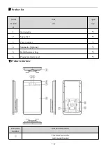
Page 8: ...7 16 RGB camera...
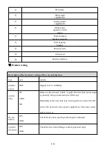
Page 18: ...18 This table is prepared according to the provisions of SJ T11364...
Page 20: ...20...
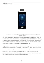
The HOTA F6 Operating Instructions Manual is a comprehensive guide that enables easy navigation and optimal use of the HOTA F6 product. This manual is available for free download from 88.208.23.73:8080, ensuring quick access to essential information, troubleshooting tips, and detailed instructions for an exceptional user experience.
Page 8: ...7 16 RGB camera...
Page 18: ...18 This table is prepared according to the provisions of SJ T11364...
Page 20: ...20...


