background image

Installationsanleitung SYNO Haubenmuffe

Installation guide SYNO Dome Closure

Instructions de montage SYNO manchon cloche

021.3811

Summary of Contents for SYNO Dome Closure series

Page 1: ...Installationsanleitung SYNO Haubenmuffe Installation guide SYNO Dome Closure Instructions de montage SYNO manchon cloche 021 3811 ...

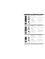
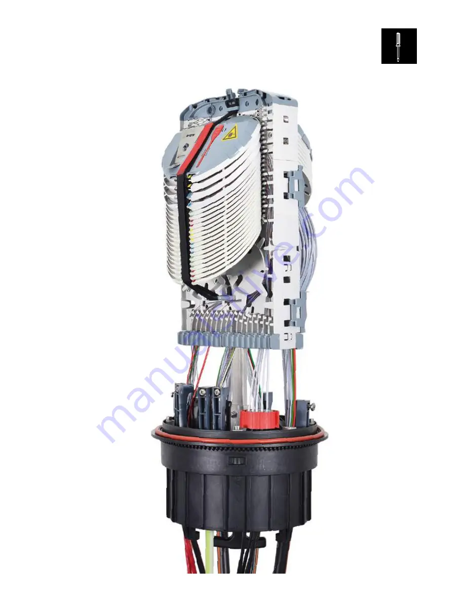
Page 2: ...nen Kit für Überlängenablage Spleisskassettendeckel mit Zubehör Trockenmittelbeutel 2x 20g Optional Ventil vormontiert SYNO Dome Closure STP48 Closure prepared for 2x 24 trays Closure dome including sealing ring Base Clamp Loose tube tray kit for loop storage Splice tray cover kit incl accessories Desiccant 2x 20g silica gel bags Optional Valve preassembled SYNO Haubenmuffe STP24 Muffe vorbereitet...

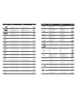
Page 3: ... No Spleisskassette SCM SC für 6 Spleisse 1 Stk 6 Spleisse 12 Stk Splice Tray SCM SC for 6 splices 1 pcs 6 splices 12 pcs R508434 R508440 Spleisskassette SCM SC für 12 HS Spleisse 1 Stk 12 HS Spleisse 12 Stk Splice Tray SCM SC for 12 HS splices 1 pcs 12 HS splices 12 pcs R804270 R804272 Spleisskassette SCM SC für 12 SW Spleisse 1 Stk 12 SW Spleisse 12 Stk Splice Tray SCM SC for 12 SW splices 1 pcs...

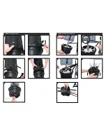
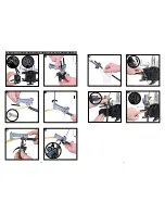
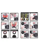
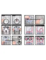
Page 4: ...A2 A3 A4 A1 A Muffe öffnen Opening closure B1 B2 B3 B4 B5 4x A5 click click B Muffe vorbereiten Closure preparation 021 3775 021 3774 021 3777 021 3776 021 3778 021 3637 021 3636 021 3635 021 3632 021 3634 ...

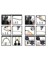
Page 5: ...t E1 E2 D3 L L 1 L 2 L1 L2 2 0m L1 L2 2 2m L1 L2 2 4m Zentralelement 9mm Central member 9mm L 2 0m L 2 2m L 2 4m L 60mm L 80mm L 65mm L 60mm L 80mm L 65mm click min 10mm C4 B4 D6 STP24 STP48 STP96 STP24 STP48 STP96 021 3807 021 3642 021 3643 021 3639 021 3779 021 3780 021 3640 021 3830 021 3814 021 3831 021 3887 021 3644 021 3645 021 3639 021 3807 021 3781 ...

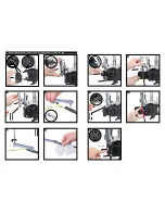
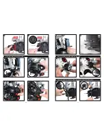
Page 6: ...ssembling Entry Kit 1x 12 21mm 1x 20 25mm 1x 20 28mm F2 F3 F4 2x F7 F8 F9 F10 F5 F6 F1 2x click press click click 021 3649 021 3655 021 3877 021 3814 021 3647 021 3761 021 3648 021 3649 021 3651 021 3782 021 3657 021 3873 021 3658 021 3812 021 3656 021 3806 021 3659 ...

Page 7: ...ing Entry Kit 2x 7 14mm 4x 5 8mm G6 G3 G4 G5 G1 G2 2x G7 G8 G9 G10 G11 click 2x press click click 021 3660 021 3877 021 3814 021 3661 021 3873 021 3662 021 3652 021 3653 021 3654 021 3669 021 3668 021 3814 021 3665 021 3666 021 3667 021 3664 021 3663 021 3806 ...

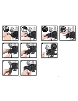
Page 8: ...ing Water Gas Termination WGT H1 H2 H3 H4 H6 H7 H8 H10 H9 H11 Min H5 L L 80mm L 65mm H12 press click press turn 2x 2x 021 3684 021 3685 021 3686 021 3689 021 3687 021 3688 021 3690 021 3676 021 3691 021 3693 021 3693 021 3692 021 3694 021 3695 021 3812 ...

Page 9: ...es Segment öffnen Open inner segment Äusseres Segment entfernen Remove outer segment J Zugentlastung mit Revolver Strain relief with revolver J1 J2 J3 J4 STOP STOP click 1 0 2 0 c m 10 20cm 021 3657 021 3873 021 3657 021 3873 021 3816 021 3816 021 3815 021 3815 021 3817 021 3806 021 3818 021 3843 021 3844 021 3848 021 3841 021 3846 021 3842 021 3847 021 3819 021 3820 ...

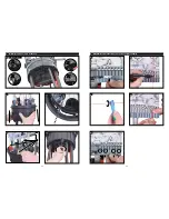
Page 10: ...3 5mm 16x 2 3mm Cable assign for Entry Kit 8x 3 5mm 16x 2 3mm L1a L1b L2 L4 L3 L6 L5 press click press click 8x 3 5mm 16x 2 3mm click 1 2 3 4 5 6 7 8 9 10 11 12 13 14 15 16 1 2 3 4 5 6 7 8 9 10 11 12 13 14 15 16 K2 Einführungskit 16x 2 3mm Entry Kit 16x 2 3mm 021 3845 021 3849 021 3821 021 3822 021 3696 021 3839 021 3840 021 3838 021 3837 021 3826 021 3814 021 3827 021 3806 021 3824 021 3814 021 3...

Page 11: ...stungseinheit Replacing strain relief 2 1 O Austausch Gelsegment bei installierten Kabel Replacing gel segment with installed cables STOP STOP click click 021 3828 021 3829 021 3814 021 3784 021 3805 021 3783 021 3805 021 3808 021 3809 021 3810 021 3877 021 3697 021 3806 021 3698 021 3709 021 3786 021 3787 021 3788 021 3785 021 3788 ...

Page 12: ...22 23 O3 O4 O5 O6 O7 O8 O9 O10 click O11 021 3699 021 3805 021 3700 021 3805 021 3701 021 3702 021 3703 021 3704 021 3707 021 3814 021 3705 021 3877 021 3706 021 3708 ...

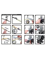
Page 13: ... P5 STOP P2 P3 P4 Kontrolle Control 4x Q Bündeladern absetzen und einlegen Loose tube stripping and fixing Q5 Q1 Q2 Q3 Q4 click 021 3710 021 3711 021 3712 021 3713 021 3714 021 3715 021 3716 021 3718 021 3719 021 3790 021 3833 021 3835 021 3789 021 3834 ...

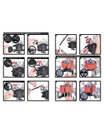
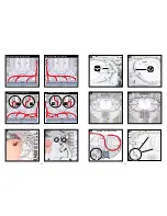
Page 14: ...und Ablage der Fasern Guidance and storage of fibers T1 T2 T3 T4 Faserkanal rechts Fiber channel right Faserkanal links Fiber channel left Zur Rückseite links To the back left Zur Rückseite rechts To the back right 021 3865 021 3864 021 3863 021 3722 021 3721 021 3723 021 3724 021 3737 021 3736 021 3832 021 3836 021 3832 021 3836 021 3832 021 3832 021 3727 021 3726 ...

Page 15: ...ft T9 T10 1 2 T11 T12 T7 T8 Zur Rückseite links To the back left Zur Rückseite rechts To the back right T13 T14 T15 Richtungswechsel Direction change 1 2 T16 2 021 3720 021 3720 021 3720 021 3791 021 3720 021 3791 021 3889 021 3728 021 3804 021 3795 021 3738 021 3739 021 3794 021 3793 ...

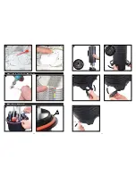
Page 16: ...rierung der Spleisskassetten Numbering trays U2 V3 V4 V1 V2 V Muffe schliessen Closing closure V5 V6 V7 click 021 3796 021 3797 021 3731 021 3730 021 3732 021 3798 021 3869 021 3867 021 3868 021 3866 021 3799 021 3733 021 3734 ...

Page 17: ... This guide shows the best practices for installation ONLY R M expressly disclaims all liability for any damage to material equipment and for any injury or death Legal health and safety regulations should have priority over best practices as shown in this guide R M does not guarantee this guide to be free of errors Products included may vary from products shown Please exercise caution ...

Reviews: