background image

R&S

®

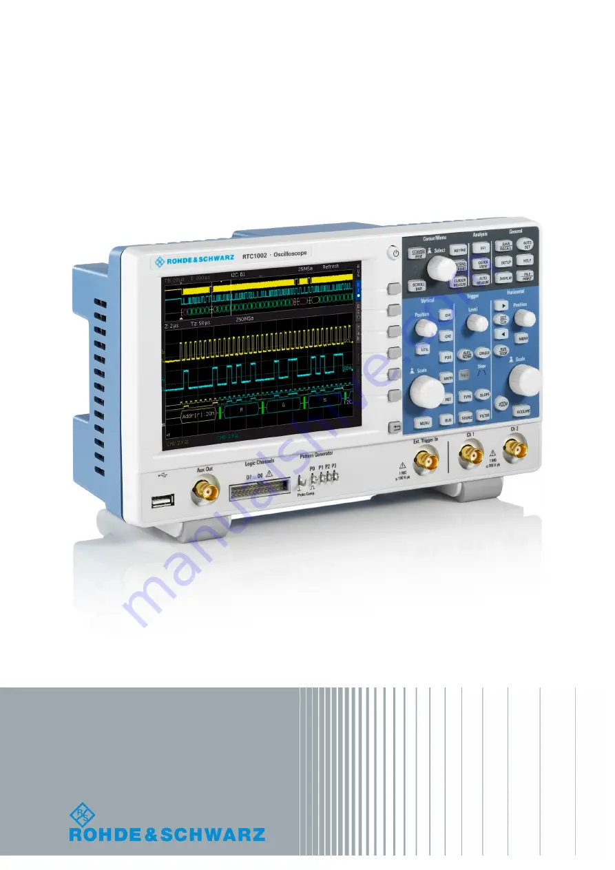
RTC1000

Digital Oscilloscope

User Manual

User Manual


1335.7352.02 ─ 02

(=S×Â2)

Summary of Contents for RTC1000

Page 1: ...R S RTC1000 Digital Oscilloscope User Manual User Manual 1335 7352 02 02 S 2...

Page 2: ...49 89 41 29 12 164 Email info rohde schwarz com Internet www rohde schwarz com Subject to change Data without tolerance limits is not binding R S is a registered trademark of Rohde Schwarz GmbH Co KG...

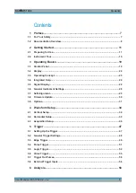
Page 3: ...cept 23 3 4 Integrated Help 24 3 5 Signal Display 24 3 6 General Instrument Settings 28 3 7 Self Alignment 29 3 8 Firmware Update 30 3 9 Options 31 4 Waveform Setup 34 4 1 Vertical Setup 34 4 2 Horizo...

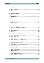
Page 4: ...erence Waveforms 97 8 3 Waveforms Traces 99 8 4 Screenshots 103 8 5 Quick Access with FILE PRINT Key 105 9 Mixed Signal Operation Option R S RTC B1 107 9 1 Using Logic Channels 107 9 2 Logic Trigger f...

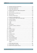
Page 5: ...Command Description 167 13 2 Common Commands 167 13 3 Acquisition and Setup 171 13 4 Trigger 198 13 5 Display 208 13 6 Measurements 215 13 7 Quickmath and Reference Waveforms 229 13 8 FFT 237 13 9 Mas...

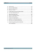
Page 6: ...uence and Synchronization 346 B 1 Preventing Overlapping Execution 346 C Status Reporting System 348 C 1 Structure of a SCPI Status Register 348 C 2 Hierarchy of status registers 349 C 3 Contents of t...

Page 7: ...d gives instructions how to prevent personal injury or damage caused by dangerous situations Safety information is provided as follows The Basic Safety Instructions in different languages are delivere...

Page 8: ...and are not overloaded Instrument damage caused by electrostatic discharge Electrostatic discharge ESD can damage the electronic components of the instrument and the device under test DUT Electrostati...

Page 9: ...d document is delivered with the instrument Instrument security procedures manual Deals with security issues when working with the R S RTC1000 in secure areas Service manual Describes the performance...

Page 10: ...atures improvements and known issues of the current firmware version and describe the firmware installation The open source acknowledg ment document provides verbatim license texts of the used open so...

Page 11: ...king material Retain the original packing material If the instrument needs to be transported or ship ped later you can use the material to protect the control elements and connectors Delivery contents...

Page 12: ...he overall load on the folded out feet must not exceed 200 N Fmax Risk of instrument damage due to overheating An insufficient airflow can cause the R S RTC1000 to overheat which can impair the measur...

Page 13: ...instrument settings To disconnect from power supply power off the instrument 2 1 3 2 Starting Up and Shutting Down To start up the instrument 1 Make sure that the R S RTC1000 is connected to the AC po...

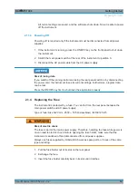
Page 14: ...es its current settings Furthermore program data can be lost Press the ON OFF key first to shut down the application properly 2 1 4 Replacing the Fuse The instrument is protected by a fuse You can fin...

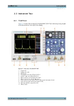
Page 15: ...view of the R S RTC1000 1 Touchscreen 2 Softkeys and menu 3 ON OFF key 4 Cursor Menu Analyze and General sections 5 Vertical Trigger and Horizontal sections 6 BNC connectors of the analog channel inp...

Page 16: ...preclude direct contact with the measurement setup Use only insulated voltage probes test leads and adapters Do not touch voltages higher than 30 V RMS or 42 V peak or 60 V DC Risk of injury and instr...

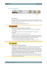
Page 17: ...Connecting other probe types can demolish the input 2 2 1 2 Other Connectors on the Front Panel PATTERN GENERATOR 8 Connectors for the pattern generator P0 P1 P2 P3 PROBE COMP 8 Probe compensation te...

Page 18: ...e instrument supports a wide range power supply It automatically adjusts to the cor rect range for the applied voltage There is no line voltage selector The AC main power switch disconnects the instru...

Page 19: ...ggles between coarse and fine resolution of the universal rotary knob The key lights up if fine resolution is active SCROLLBAR Activates or deactivates the virtual screen KEYPAD Opens the on screen ke...

Page 20: ...INT can save instrument settings signals screenshots or start a printout 3 1 4 Vertical Section The Vertical section features all controls for analog channels POSITION knob Sets the vertical position...

Page 21: ...evel AUTO NORM Toggles between auto and normal trigger mode Trigg d The LED lights up if the instrument found a trigger event TYPE Opens a menu to select the trigger type SOURCE Opens a menu to select...

Page 22: ...ds on the time base If a zoom window is active the knob sets the zoom position If markers are set the knob sets the marker position MENU Opens a menu to set the trigger position TIME BASE knob Sets th...

Page 23: ...ngs of the selected channel 9 Vertical settings of active waveforms vertical scale in V div coupling and bandwidth limit if set Channel 1 is selected 10 Measurement results 11 Reference potentials of...

Page 24: ...oggle a value The selected value is marked in blue Some functions must be activated and require value selection Pressing the softkey toggles between OFF and the last set value Use the UNIVERSAL knob t...

Page 25: ...re dots If inverted rare events are displayed with higher brightness To capture rare events in a signal this setting can be used in combination with persistence FALSE COLORS Converts the brightness le...

Page 26: ...y the grid of the R S RTC1000 has 8 vertical divisions It has also a virtual range of 20 divisions These virtual divisions can be used entirely by the optional digital channels D0 to D7 the mathematic...

Page 27: ...the INTENS PERSIST key is illuminated in white press this key again 2 Use the menu functions to adjust the settings The following settings are available TRACE GRID BACKLIGHT Use the Universal knob to...

Page 28: ...isplay of the waveform becomes darker in 50 ms inter vals and is erased after 300 ms AUTOMATIC The instrument sets the optimal persistence time OFF Persistence is deactivated BACK GROUND When enabled...

Page 29: ...when screenshots are printed MENU OFF Selects whether you close the menus manually or they are closed automatically after a specified time DEVICE LOGO IN SCREENSHOT If activated the R S logo is print...

Page 30: ...USB flash drive 3 8 Firmware Update Your instrument is delivered with the latest firmware version Firmware updates are provided on the Internet at www rohde schwarz com firmware rtc1000 Along with th...

Page 31: ...n on the bar code sticker at the rear panel and in SETUP menu DEVICE INFORMATION The license key is provided in written form or in a file Unregistered licenses must be registered in the R S License Ma...

Page 32: ...d a key in written form a Select INPUT KEY MANUALLY b Enter the key 7 If you received a key in digital form as a file a Select READ KEYS FROM LICENSE FILE b Select the Front storage and change directo...

Page 33: ...Operating Basics R S RTC1000 33 User Manual 1335 7352 02 02 d Select LOAD 8 If you want to activate several options repeat step 6 or 7 for each option 9 Restart the instrument Options...

Page 34: ...be Compensation 37 4 1 1 Vertical Controls In the Vertical section of the front panel you select the channel set scale and position and open the vertical menu The key of the selected channel lights up...

Page 35: ...h between input connector and the following internal signal stage The current coupling of each channel is shown in the channel labels below the grid AC AC coupling blocks the DC component of the signa...

Page 36: ...delivered probes R S RT ZP03 probe can be switched 10 1 or 1 1 The instrument does not detect the probe attenuation automatically Therefore make sure to set up the correct attenuation factor manually...

Page 37: ...Opens on screen keypad to enter a label text The maximum name length is 8 characters and only ASCII characters provided on the on screen keypad can be used If you previously have selected a text from...

Page 38: ...d level The next pin supplies a square wave signal for the adjustment To perform probe compensation using the wizard 1 Press the SETUP key in the General section 2 Press the PROBE ADJUST softkey 3 Fol...

Page 39: ...igger point even outside the screen The reference point is the zero point of the diagram and the rescaling center of the time scale on the screen If you modify the time scale the reference point remai...

Page 40: ...e resolution and the more details of the waveform are visible A sufficient resolution is essential for correct reconstruction of the waveform If the sig nal is undersampled aliasing occurs a false wav...

Page 41: ...time these values create an envelope surrounding the signal AVERAGE The average is calculated from the data of the current acquisition and some consecutive acquisitions before The method reduces rando...

Page 42: ...so the adjoining sample points are considered by this curve This interpolation method is the default method It is precise and shows the best signal curve Linear Uses a line to connect acquired data po...

Page 43: ...he instrument sets the maximum sampling rate while using the maximum memory available Thus it displays the maximum amount of data Each column in the signal window displays up to 40 detected data value...

Page 44: ...s displayed depends on the displayed time window and the current sampling rate When peak detection is activated each column displays up to 5 pairs of min max values The memory depth is at least twice...

Page 45: ...STOP mode If the time base allows of the display of each sample point all three settings behave identically except used memory depth and signal update rate Advantages and disadvantages of the record m...

Page 46: ...ts Slow response to operation or change in signal Low signal update rate Higher visibility of noise For signals with high frequency parts Assessment of small signal details Automatic Average signal up...

Page 47: ...ger type and its filter setup Trigger mode In addition the trigger position and the reference point are important to display the interesting part of the signal See Chapter 4 2 Horizontal Setup on page...

Page 48: ...displayed press the SINGLE key The key is highlighted in white when the SINGLE mode is active In normal trigger mode the trigger system is now activated and the RUN STOP key is blinking If the trigger...

Page 49: ...rigger The selection is indicated by the Slope LEDs FILTER Opens a menu to set up the trigger condition for the selected trigger type 5 3 Edge Trigger The edge trigger is the most common trigger type...

Page 50: ...is coupled through a high pass filter with a minimum cut off fre quency 3 dB of 30 kHz Use this coupling type only with high frequency signals LOWPASS The trigger signal is coupled through a low pass...

Page 51: ...polarity press the SLOPE key repeatedly The selected polarity is shown above the key and on top of the grid in the display 3 To set the trigger level turn the LEVEL knob 4 Select FILTER The filter se...

Page 52: ...the reference time t1 Not t1 ti t2 Triggers on pulses longer than the reference time t2 and shorter than the reference time t1 5 5 Logic Trigger Using the logic trigger also known as pattern trigger...

Page 53: ...you want to trigger on the true or false pattern TRIGGER ON Figure 5 1 Logic trigger pattern setup LOGIC CHANNEL Selects the channel for which you want to set the logic state The setting is always act...

Page 54: ...t Define a minimum time during which the signals match the pattern condition ti t or ti t and TIME t Triggers if the pattern condition changes before or after the specified time ti t TIME t and Variat...

Page 55: ...and adjusted accordingly 5 6 Video Trigger The video or TV trigger is used to analyze analog baseband video signals You can trigger on baseband video signals from standard definition and high definit...

Page 56: ...o lines You can define the exact line between 1 and 625 or trigger on all lines FRAME Triggers on the start of half frames either on odd or on even half frames 5 7 Trigger Out Pulses You can output a...

Page 57: ...Trigger R S RTC1000 57 User Manual 1335 7352 02 02 Figure 5 3 External trigger signal External Trigger Input...

Page 58: ...2 MSa in interlaced mode Thus the instrument can record long and complex signals To analyze these records in detail use the zoom function Press the ZOOM key in the Horizontal section The screen is di...

Page 59: ...w is active Turn the SCALE knob in the Horizontal section to change the zoom time base Z 2 To move the position of the zoomed section Tz turn the POSITION knob in the Horizontal area To set the time b...

Page 60: ...rkers to identify areas of interest you want to zoom into and quickly move through the data You can set up to 8 time markers To set markers 1 Press the MENU key in the Horizontal section 2 Press the u...

Page 61: ...To toggle markers use the ARROW keys The selected marker is set to the center of the screen Thus you can quickly compare marked signal sections in zoom mode 2 To delete a marker set it to the center...

Page 62: ...tion In other words the time base x is replaced by amplitude val ues of a second source The resulting XY display for harmonic signals is known as Lissajous figures They are used to analyze frequency a...

Page 63: ...cal operators on channel 1 and channel 2 Using the advanced mathematics MA you can create up to five formulary sets Each formulary set can include up to five equations Equations provide more oper ator...

Page 64: ...ort math menu opens 2 Press the lowest softkey until QM is illuminated in red Figure 6 5 Quick Mathematics short menu 3 Configure the math function a Press the upper softkey to choose the first operan...

Page 65: ...ations Equations provide more operators and more sources than the Quick Mathematics Formulary sets can be saved and loaded for further use 6 4 2 1 To Create a Formulary Set and Its Equations 1 Press t...

Page 66: ...knob in the Cursor Menu section 7 To add an equation a Use the Universal knob to select new in the editor b Press ADD The new equation is added and can be edited 8 To delete an equation from the formu...

Page 67: ...arious units for all usual calculations are available The selected equation unit is applied to the channel description cursor types and automatic measurement types 5 To change the equation name a Pres...

Page 68: ...ource for MA3 the additional sources are MA1 and MA2 for MA4 it is MA1 MA2 and MA3 and so on 9 To set a constant press EDIT CONSTANT and the UNIVERSAL knob in the CURSOR MENU section to choose one of...

Page 69: ...r the FILE NAME c Optionally add a COMMENT 4 To use a saved formulary set press LOAD 6 4 2 4 Example This example shows the analysis of an electrical energy waveform The voltage across the load is mea...

Page 70: ...NT to define the constant NUMERIC INPUT 0 1 Figure 6 10 Definition of the current equation The correct scaling and the units for cursors and automatic measurements are defined To define the POWER equa...

Page 71: ...d and the results can be displayed and analyzed The math analysis can be performed with cursor or automatic measurement functions All measurement results are correctly shown with correct units Ampere...

Page 72: ...ain settings span and center If the FFT grid is active it is outlined in white and the SCALE knob in the Horizontal section changes the span of the FFT The span is specified in Hz Hertz and identifies...

Page 73: ...ve lope curve is reset AVERAGE Calculates the mean value from several spectra to reduce noise The softkey AVERAGES selects the number of spectra used to calculate the mean value POINTS Selects the max...

Page 74: ...he Blackman window the amplitudes can be measured precisely However determining the fre quency is more difficult Use this window to measure signals with single frequencies to detect harmonics and accu...

Page 75: ...the display You can also start certain actions if an error is discovered To access the Pass Fail test menu 1 Press the UTIL key in the Vertical section 2 On menu page 2 2 press PASS FAIL 3 To open th...

Page 76: ...d you can use the menu to change the limits for the test 5 To store the mask permanently to a USB flash drive or in the internal memory press SAVE 6 To return to the PASS FAIL menu press the Back key...

Page 77: ...acquisition of signals is continued press PAUSE 3 To resume the test and to continue all event counters press PAUSE again 4 To finish the test press TEST Stop The event and time counters are stopped...

Page 78: ...front panel BNC connectors see Chapter 6 7 1 In circuit Tests on page 81 The test principle is a generator within the R S RTC1000 which generates a 50 Hz or 200 Hz 10 sine wave The sine wave feeds the...

Page 79: ...rement the gain of a transis tor cannot be determined however the B C B E C E diodes can be measured With this exception the diodes can be measured without fear of destruction as the maxi mum voltage...

Page 80: ...Analysis R S RTC1000 80 User Manual 1335 7352 02 02 Figure 6 16 Exmaple results of component tests Component Test...

Page 81: ...ter 3 Compare the screen displays Sometimes the unit under test can already contain an intact portion of the same type for example with stereo circuits push pull circuits or symmetrical bridge cir cui...

Page 82: ...Crest factor X max XRMS PEAK PEAK Maximum Minimum PEAK Maximum PEAK Minimum Figure 6 17 Digital Voltmeter The primary measurement is shown in a large font and the secondary measure ment in a small fo...

Page 83: ...ck view function provides a quick overview of the typical signal characteristics Measurement results are displayed at the bottom of the screen and with a cursor on the signal Only one channel can be a...

Page 84: ...e Depending on the mea surement type up to three cursor lines are available To move cursors 1 To select the cursor line press the Universal knob in the Cursor Menu section 2 To position the cursor lin...

Page 85: ...allows fast and typi cally optimal automatic positioning of the cursors Mostly only fine tuning is required If SET TO TRACE does not provide the anticipated results due to complex signals use the key...

Page 86: ...atio between the first two cursors and the first and the third cursor The measurement val ues are displayed in four formats floating point percent degrees and radians Ratio Y Ratio Y provides three cu...

Page 87: ...pan set by the cursors The rise time identifies the time in which the signal rises or falls from 10 to 90 of its amplitude or from 20 to 80 V Marker V Marker provides two cursors and measures three vo...

Page 88: ...tance the period to be measured is not completely displayed and cannot be identi fied 7 3 1 Settings for Automatic Measurements Press the AUTO MEASURE key in the Analysis section Figure 7 2 Auto measu...

Page 89: ...f the screen is used for the measurement RMS Value RMS Value measures the effective value of the displayed signal If the signal is peri odic the first period on the left of the screen is used for the...

Page 90: ...rshoot The mea surement requires at least one complete period of a triggered signal Base Level Base Level measures the mean voltage level of the lower square wave VBase The measurement calculates the...

Page 91: ...e of the signal period Rise Time 90 Rise Time 80 Measures the rise time of the first rising slope in the display tr tr80 The rise time is the time in which the signal rises from 10 to 90 or from 20 to...

Page 92: ...n value A pulse that passes the mean value only once is not calculated Count P Count P counts negative pulses in the display A negative pulse consists of a falling slope followed by a rising slope The...

Page 93: ...User Manual 1335 7352 02 02 Trigger Period Trigger Period measures the duration of periods of the trigger signal TTr with a hard ware counter The source for the measurement is the current trigger sou...

Page 94: ...ument settings which are intended for further use on the instrument are usually saved to the internal storage INT You can also store them to the external storage or move them to the other location usi...

Page 95: ...complete measurement con figuration The softkey DEVICE SETTINGS allows you to save current instrument settings load saved settings and import or export instrument settings to USB flash drive Figure 8...

Page 96: ...ies 4 Press ACCEPT DIR 5 Press FILE NAME Change the file name if necessary SET01 is the default name 6 To enter an optional comment press COMMENT The comment is displayed in the file manager footer if...

Page 97: ...AME 5 Press IMPORT EXPORT to copy the selected settings file To restore default instrument settings In the SAVE RECALL DEVICE SETTINGS menu press DEFAULT SETT 8 2 Reference Waveforms References or ref...

Page 98: ...per DISPLAY softkey Select one of the references RE1 to RE4 c Press the lower DISPLAY softkey The data is written to the reference storage and the reference waveform is dis played 4 To save a referenc...

Page 99: ...change the file name press DEST NAME Enter the file name 5 To change the file format press DEST FORMAT 6 Select the target format See also Chapter 8 3 1 Waveform File Formats on page 101 7 Press IMPO...

Page 100: ...ference or pod You can select only active waveforms You can also save all visible channels to one file 5 Press FILE NAME Enter the file name 6 Press FORMAT Select the target format see Chapter 8 3 1 W...

Page 101: ...d the lines are separated by line breaks r n 0x0D 0x0A Values are listed in scientific notation The first column contains the time values of the samples in relation to the trigger point and the second...

Page 102: ...0E 02 8 3 1 3 BIN Format BIN files contain only binary amplitude values but no time values Each value has a word size of 8 or 16 or 32 bit the word size is the same throughout the file You can set the...

Page 103: ...USB flash drive 2 In the SAVE RECALL menu press SCREENSHOTS 3 Press STORAGE Select the target directory for the file Screenshots are always saved to USB flash drive FRONT a To sort several settings f...

Page 104: ...rear USB port and identified by the instrument See also Chapter 8 4 2 Printing Screenshots on page 104 8 4 2 Printing Screenshots You can create a screenshot of the current display of your waveforms a...

Page 105: ...he FILE PRINT key If you assign the print function to the FILE PRINT key a screenshot is printed on the connected printer when you press the FILE PRINT key 1 Configure the FILE PRINT key a Press SAVE...

Page 106: ...P Stores screenshots and settings PRINT Prints directly to a connected printer Figure 8 6 Definition of FILE PRINT key 4 Configure the settings for the selected action as described in the previous sec...

Page 107: ...1 clause 5 2 4 101 Therefore the measure ments are sensitive to electromagnetic interference Consider additional shielding methods to avoid interference To ensure accurate measurements attach the gro...

Page 108: ...or User2 Adjust the logic level from 2 V to 8 V with the universal knob or the KEYPAD key To activate and scale logic channels 1 To switch on the digital channels press the POD key in the Vertical se...

Page 109: ...ize of logic channels 1 Press the POD key in the Vertical section until it lights up 2 Press the MENU key in the Vertical section to open the POD menu 3 Press SET TO DEFAULT POS SIZE to reset the posi...

Page 110: ...n determine several parameters using cursor mea surements CURSOR MEASURE key The following measurement types are available TIME The display shows the time position of both cursors relative to the trig...

Page 111: ...u can use logic channels as input sources of various buses Parallel buses are dedi cated for analysis of logic channels Serial buses accept analog and digital channels as input The general usage of bu...

Page 112: ...e UNIVERSAL knob to assign a logic channel to the selected bit Alter natively you can press the SOURCE repeatedly 5 If you have selected PARALLEL CLOCKED as bus type press the bottom soft key CONTROL...

Page 113: ...able 9 1 Content of the parallel bus table Column Description Start Time Time of frame start in relation to the trigger point Data Values of the data bytes To trigger on parallel buses you can use the...

Page 114: ...e input signals for circuits testing and other purposes The generated signal is output at the AUX OUT connector 1 Press the UTIL key in the Vertical section 2 Press FUNCTION GEN 3 Select the parameter...

Page 115: ...or the selected pattern Table 10 1 Settings for the pattern generator Pattern Settings Square wave Frequency polarity duty cycle Counter Frequency counting direction Arbitrary Timing pattern input Man...

Page 116: ...a 4 bit wide and a 2048 sample deep arbitrary pattern The created pat tern can be stored and loaded If a pattern is generated when you call the arbitrary function the pattern is retained Thus you can...

Page 117: ...turning the UNIVERSAL knob DELETE ALL Ddeletes the pattern The pattern length is reset to 1 All values are set to 0 TIMING SETUP Defines the time characteristics of the pattern BIT TIME Sets length of...

Page 118: ...edges do not alternate If the burst is enabled the idle time is applied between the patterns and the pattern is issued n times MAN The pattern is issued manually by pressing the MANUAL key If the burs...

Page 119: ...Signal P1 P2 P3 P0 SPI Clock MOSI MISO Chip Select I2C Data SDA no signal no signal Clock SCL UART RX no signal no signal TX CAN CAN L no signal no signal CAN H LIN Low no signal no signal High An inf...

Page 120: ...ype protocol specific settings Decoding Display of decoded data zoom bus table Trigger Start stop serial pattern 11 1 Bus Configuration Before you can adjust the settings for the trigger and decoding...

Page 121: ...ailable with R S RTC K3 Figure 11 1 Menu for bus definition To configure the selected bus type Press CONFIGURATION The configuration menu for the selected bus type opens A menu description can be foun...

Page 122: ...me in the editor The name is displayed on the grid and the printout 11 2 Bus Table Decode Results The bus table shows the decode results of the bus You can adjust the content of the table and export t...

Page 123: ...ach frame one line is written to the file for example Bus table BUS1 I2C Clock SCL D0 Dates SDA D1 Frame Mark Start time s Type ID Length Date Condition 1 197 89200e 6 Read 0x2D 5 0xF110E55D31 OK 2 28...

Page 124: ...frame data packet This column is labeled as TIME DIFF If deactivated the absolute time in relation to the trigger point is displayed in the col umn START TIME POSITION Moves the bus table to the top o...

Page 125: ...t after the last byte Data a series of data bytes with an ACK bit after each byte Stop condition rising slope on SDA serial data while SCL serial clock is high 11 3 1 I2C Bus Configuration Before you...

Page 126: ...ress is interpreted inclusive ADR RW or without the Read Write bit ADDR ONLY A small window provides information about the current settings 5 Press the Back softkey twice to close all menus 11 3 2 I2C...

Page 127: ...er Chapter 10 2 5 Serial Buses on page 118 START Triggers on the frame start sequence The start sequence is the falling slope on SDA when SCL is high STOP Triggers on the frame stop sequence The stop...

Page 128: ...mode by using 4 of 16 reserved addresses and can be used simultaneously For a 10 bit address length a total of 1136 addresses 1024 128 16 is available The highest 10 bit address is 1023 0x3FF The sel...

Page 129: ...ate Repeat until all bits are set If hexadecimal input is selected only the entire byte can be set to X Use the softkey SELECT BYTE to choose one of the bytes depending on the available number of byte...

Page 130: ...has been decoded currently no data available ADDR ERR incomplete frame decoding INS the frame is not contained in the acquisition the acquired part of the frame is valid 11 4 SPI SSPI BUS Option R S...

Page 131: ...se and selects a slave data can be transmitted in either one direction or simultaneously in both directions Figure 11 7 Simple configuration of SPI bus 11 4 1 SPI SSPI Bus Configuration Before you con...

Page 132: ...ve is the default setting 5 If Clk is selected press SLOPE to decide whether the data is stored with rising or falling slope rising slope is the default setting 6 If Data is selected press ACTIVE to a...

Page 133: ...ervals between the data packets are shorter than the time out these packets belong to the same frame A small window provides information about the current settings 7 Press BIT ORDER to determine if th...

Page 134: ...n position in the frame BIT OFFSET SER PATTERN Defines the position of the first bit of the configured bit sequence within the frame The bits in front of it have no impact on the trigger event For exa...

Page 135: ...has been decoded currently no data available INS the frame is not contained in the acquisition the acquired part of the frame is valid 11 5 UART RS 232 BUS Option R S RTC K2 For UART RS 232 bus trigge...

Page 136: ...ls see To set the threshold for logic states on page 108 The default value is 500 mV To select the UART bus 1 Press the BUS key in the Vertical section 2 In the short menu select the bus B1 or B2 3 In...

Page 137: ...bol PARITY Parity bits are used to detect errors during a transmission None No parity bits Even If the number of ones in a specific set of bits is uneven without parity bit the parity bit is set to 1...

Page 138: ...BUS Triggering After the bus configuration is completed you can trigger on various events To trigger on events 1 In the Trigger section press the TYPE key 2 Select SERIAL BUS 3 Press the SOURCE key i...

Page 139: ...rst low bit after a stop bit FRAME START Defines the first start bit after idle time frame start as trigger condition SYMBOL N Triggers on the Nth symbol in a frame ANY SYMBOL Triggers on a symbol pat...

Page 140: ...ttern the pattern size The symbol length is configured in the bus configuration PATTERN INPUT See PATTERN INPUT on page 129 PARITY ERROR Triggers on a parity error FRAME ERROR Triggers on a frame erro...

Page 141: ...ata words State Frame Status OK Frame is valid DATA during acquisition start end only the frame start frame end has been decoded currently no data available INS the frame is not contained in the acqui...

Page 142: ...CRC acknowledge bit and an end bit 11 6 1 CAN Bus Configuration Before you configure the bus set the correct logic level threshold For analog channels see THRESHOLD menu on page 36 For digital channel...

Page 143: ...ted to CAN High and the negative input to CAN Low If the probe is connected with reversed polarity select CAN L SAMPLE POINT Sets the position of the sample point within the bit in percent of the nomi...

Page 144: ...Triggers on the selected frame type For data and remote frames also select the iden tifier type 11 bit 29 bit or any ERROR Triggers on general frame error OVERLOAD Triggers on CAN overload frames DAT...

Page 145: ...nes the address of the data pattern ID TYPE the length of the identifier 11 bit for CAN base frame format or 29 bit for extended CAN frames Compare function COMPARE on page 145 Address pattern PATTERN...

Page 146: ...Serial Bus Analysis R S RTC1000 146 User Manual 1335 7352 02 02 Figure 11 16 Decoded CAN bus Figure 11 17 Example of a CAN bus table CAN Bus Option R S RTC K3...

Page 147: ...rror INS the frame is not contained in the acquisition the acquired part of the frame is valid 11 7 LIN Bus Option R S RTC K3 For CAN bus trigger and decoding you need the R S RTC K3 option The LIN bu...

Page 148: ...the threshold for logic states on page 108 The default value is 500 mV To select the LIN bus 1 Press the BUS key in the Vertical section 2 In the short menu select the bus B1 or B2 3 In the BUS menu p...

Page 149: ...IN Bus Triggering After the bus configuration is completed you can trigger on various events To trigger on events 1 In the Trigger section press the TYPE key 2 Select SERIAL BUS 3 Press the SOURCE key...

Page 150: ...calculates the CRC and transmits the result in a CRC sequence The receiver calculates the CRC in the same way An error occurs if the calculated result differs from the received CRC sequence PARITY Tr...

Page 151: ...BYTES the number of data bytes to be compared Compare function COMPARE on page 151 Data pattern PATTERN INPUT on page 129 COMPARE Defines the comparison function If the pattern includes at least one...

Page 152: ...Serial Bus Analysis R S RTC1000 152 User Manual 1335 7352 02 02 Figure 11 21 LIN bus Figure 11 22 Example of a LIN bus table LIN Bus Option R S RTC K3...

Page 153: ...s Data Values of the data bytes Chks Checksum value State Frame state OK Frame is valid DATA during acquisition start end only the frame start frame end has been decoded currently no data available SY...

Page 154: ...lly Auto matic private IP addressing APIPA is not supported Manually the address must be set manually By default the instrument is configured to use automatic configuration and obtain all address info...

Page 155: ...of these parameters Note that refreshing the values for example after disconnecting the LAN cable and reconnecting it can take a while depending on the network responsiveness Off Use this setting if...

Page 156: ...the computer ping IP address Using the IP address in remote control The IP address of the instrument is part of the resource string to identify and control the instrument The resource string has the...

Page 157: ...nstrument data Check network settings 12 2 1 Accessing the Instrument Using a Web Browser To access the R S RTC1000 you need a LAN connection and the IP address of the instrument 1 Set up a LAN connec...

Page 158: ...It also provides instrument control functions and screenshot settings Instrument control Run and Stop start and stop continuous acquisition same as RUN STOP key on the instrument Single SINGLE key on...

Page 159: ...save the screenshot right click the picture and select Save image as 12 2 4 SCPI Device Control On the SCPI Device Control page you can check how the transfer of remote com mands is working You can en...

Page 160: ...of your browser On the instrument the files are saved in the internal storage You can also load reference waveforms and instrument settings from file to the instru ment To save data to a file on the c...

Page 161: ...Setting page you can change the port settings switch off DHCP address and enter an IP address in a more comfortable way than directly on the instru ment To take effect of the changes Submit them to t...

Page 162: ...ess the instrument via USB Connecting the instrument using USB 1 Connect the USB cable to the USB type B connector at the rear panel of the instru ment and to the computer 2 Press the SETUP key 3 Pres...

Page 163: ...the virtual COM port VCP to communicate with the measuring instru ment You can use any terminal program to send SCPI commands USB VCP requires a USB VCP driver on the controlling computer If the compu...

Page 164: ...ent data Files are created on demand See Live Data on page 165 Upload Read write folder to send instrument settings files firmware update files and license key files to the oscilloscope The content is...

Page 165: ...n the Acquisition Memory folder provide data from the acquisition memory and the files in the DISPLAY DATA folder provide the visible waveform data in various for mats The file content is generated wh...

Page 166: ...rol When you switch on the instrument it is always in manual operation state local state and can be operated using the front panel When you send a command from the control computer it is received and...

Page 167: ...setting are indicated as Setting parameters Parameters required only to refine a query are indicated as Query parameters Parameters that are only returned as the result of a query are indicated as Re...

Page 168: ...B the standard event register ESR and the EVENt part of the QUEStionable and the OPERation registers to zero The command does not alter the mask and transition parts of the registers It clears the out...

Page 169: ...een executed This is used for command synchronization OPT Option identification query Queries the options included in the instrument For a list of all available options and their description refer to...

Page 170: ...ted value This command deter mines under which conditions a service request is triggered Parameters Contents Contents of the service request enable register in decimal form Bit 6 MSS mask bit is alway...

Page 171: ...until all preceding commands have been executed and all signals have settled see also command synchronization and OPC Usage Event 13 3 Acquisition and Setup Starting and Stopping Acquisition 171 Time...

Page 172: ...Gle Usage Event Asynchronous command STOP Stops the running acquistion Usage Event Asynchronous command 13 3 2 Time Base TIMebase SCALe 172 TIMebase RATime 173 TIMebase ACQTime 173 TIMebase RANGe 173...

Page 173: ...fault unit s TIMebase RANGe AcquisitionTime Defines the time of one acquisition that is the time across the 12 divisions of the dia gram Timebase Scale 12 Parameters AcquisitionTime Range 12 ns to 600...

Page 174: ...Rage COMPlete 175 ACQuire WRATe 176 ACQuire POINts VALue 176 CHANnel m TYPE 176 CHANnel m ARIThmetics 177 TIMebase ROLL ENABle 177 ACQuire FILTer FREQuency 178 ACQuire POINts ARATe 178 ACQuire SRATe 1...

Page 175: ...tive signal at a different time in relation to the trigger point RST RTIM ACQuire INTerpolate Interpolation Defines the interpolation mode Parameters Interpolation LINear SINX SMHD LINear Linear inter...

Page 176: ...d sample rate using the full memory depth maximum record length MWAVeform Maximum waveform rate The instrument combines sample rate and memory depth to acquire at maximum waveform acquisition rate In...

Page 177: ...waveform from several consecutive acquisi tions of the signal Suffix m The command affects all channels regardless of the indicated channel number The suffix can be omitted Parameters TrArithmetic OFF...

Page 178: ...t Hz ACQuire POINts ARATe Retrieves the sample rate of the ADC that is the number of points that are sampled by the ADC in one second Return values AcquisitionRate ADC sample rate in Hz Usage Query on...

Page 179: ...ype REFresh SMOoth AVERage ENVelope FILTer REFresh The aquisitions are displayed as they are done SMOoth Calculates a mean value of several adjacent sample points Thus smoothing is a moving average th...

Page 180: ...Set 182 CHANnel m BANDwidth 182 CHANnel m POLarity 182 CHANnel m OVERload 182 CHANnel m SKEW 183 CHANnel m THReshold 183 CHANnel m THReshold FINDlevel 183 CHANnel m THReshold HYSTeresis 183 CHANnel m...

Page 181: ...ion Range 1e 3 to 10 RST 5e 3 CHANnel m RANGe Range Sets the voltage range across the 8 vertical divisions of the diagram Use the com mand alternativly instead of CHANnel m SCALe Suffix m Selects the...

Page 182: ...ndwidthLimit FULL B20 FULL Use full bandwidth B20 Bandwidth limit 20 MHz RST FULL CHANnel m POLarity Polarity Turns the inversion of the signal amplitude on or off To invert means to reflect the volt...

Page 183: ...ters Skew Deskew value in s CHANnel m THReshold Threshold Threshold value for digitization of analog signals If the signal value is higher than the threshold the signal state is high 1 or true for the...

Page 184: ...m Selects the input channel 1 2 Parameters State ON OFF RST OFF 13 3 5 Waveform Data FORMat DATA 185 FORMat BORDer 185 CHANnel m DATA 186 CHANnel m DATA HEADer 186 CHANnel m DATA POINts 187 CHANnel m...

Page 185: ...blocks Accuracy is always 32 The query returns REAL 32 UINTeger Unsigned integer format binary values with length 8 or 16 bit UINT 8 or UINT 16 The data range for UINT 8 is 0 to 255 the data range fo...

Page 186: ...lues Data Comma separated list of vertical values voltages of recorded waveform samples Example CHAN1 DATA 0 125000 0 123016 0 123016 0 123016 0 123016 0 123016 Usage Query only CHANnel m DATA HEADer...

Page 187: ...memory Note Reading the complete memory is only possible in STOP mode and if maximum sample rate is set ACQuire WRATe ACQ WRAT MSAM DMAXimum Display Maximum Number of samples in the current waveform r...

Page 188: ...data format is defined FORM UINT 8 16 32 Suffix m Selects the input channel 1 2 Return values Xorigin Time in s Usage Query only CHANnel m DATA YINCrement Returns the voltage value per bit of the indi...

Page 189: ...ata can be used in MATLAB for example Use this command only for envelope waveforms For other channel waveforms use CHANnel m DATA Suffix m Selects the input channel 1 2 Return values Data Comma separa...

Page 190: ...the indicated waveform The command is rele vant for data conversion if binary data format is defined FORM UINT 8 16 32 Suffix m Selects the input channel 1 2 Return values Xorigin Time in s Usage Que...

Page 191: ...WAVeform NAME 191 EXPort WAVeform SAVE 192 EXPort WAVeform SOURce WaveformSource Defines the waveform to be exported Parameters WaveformSource CH1 CH2 D0 7 QMA RE1 4 CH1 CH2 Analog channels CH1 CH2 D0...

Page 192: ...form and starts the export to USB drive Usage Event 13 3 7 Logic Channel LOGic l POSition 192 LOGic l SIZE 193 LOGic l STATe 193 LOGic l LABel 193 LOGic l LABel State 193 POD THReshold 193 POD THResho...

Page 193: ...he label for the logic channel Suffix l Selects the logic channel 0 7 Parameters Label String value xxxxxxxx with maximum 8 ASCII characters LOGic l LABel State Label Switches the label of the logic c...

Page 194: ...Set the user defined threshold for the pod Suffix u Select the user setting USER1 USER2 Parameters Threshold Level Threshold level in V Range 2 to 8 V POD State State Switches the Pod on or off Param...

Page 195: ...eturned samples for the selected range If ACQuire WRATe is set to MSAMples maximum sample rate the memory usually contains more data samples than the screen can display In this case you can decide whi...

Page 196: ...value per bit of the indicated waveform The command is relevant for data conversion if binary data format is defined FORM UINT 8 16 32 Return values Yincrement Voltage in V Usage Query only POD DATA...

Page 197: ...le Return values CurrentState Range 0 1 Usage Query only 13 3 8 Probes PROBe m SETup TYPE 197 PROBe m SETup ATTenuation UNIT 197 PROBe m SETup ATTenuation MANual 198 PROBe m SETup ATTenuation AUTO 198...

Page 198: ...e attenuation of an automatically detected probe Suffix m Selects the input channel 1 2 Return values ProbeAttenuation Range 0 001 to 1000 Usage Query only 13 4 Trigger General A Trigger Settings 198...

Page 199: ...eform only if a trigger occurs RST AUTO TRIGger A LEVel n VALue Level Sets the trigger treshold voltage for edge and width trigger Suffix n Selects the trigger input 1 2 selects the corresponding chan...

Page 200: ...l option is installed RST EDGE TRIGger A HOLDoff MODE HoldOffMode Enables or disables the holdoff time Parameters HoldOffMode TIME OFF RST Off TRIGger A HOLDoff TIME HoldOffTime Defines the holdoff ti...

Page 201: ...OURce is set to EXTernanalog Parameters ExternCoupling AC DC RST AC TRIGger OUT POLarity Polarity Sets the polarity of the trigger out pulse Parameters Polarity POSitive NEGative RST POS TRIGger OUT P...

Page 202: ...lter removes the DC offset voltage from the trigger signal HF High frequency coupling A 15 kHz high pass filter removes lower frequencies from the trigger signal Use this mode only with very high freq...

Page 203: ...he given limit s Parameters RangeMode WITHin OUTSide SHORter LONGer WITHin OUTSide Triggers on pulses inside or outside a range defined by time delta The time is specified with TRIGger A WIDTh WIDTh t...

Page 204: ...LINE 205 TRIGger A TV STANdard Standard Selects the color television standard Parameters Standard PAL NTSC SECam PALM I576 P720 P1080 I1080 RST PAL TRIGger A TV POLarity Polarity Sets the polarity of...

Page 205: ...080 depending on the TV stan dard RST 1 13 4 5 Pattern Logic Trigger TRIGger A PATTern SOURce 205 TRIGger A PATTern FUNCtion 206 TRIGger A PATTern CONDition 206 TRIGger A PATTern MODE 206 TRIGger A PA...

Page 206: ...one of the channels must have the required state RST AND TRIGger A PATTern CONDition ConditionString Sets the trigger point depending on the result of the logical combination of the channel states Par...

Page 207: ...t unit s TRIGger A PATTern WIDTh DELTa PatternDelta Defines a range around the pattern width value specified using TRIGger A PATTern WIDTh WIDTh Parameters PatternDelta t Variation Range 8 00E 09 to m...

Page 208: ...lay DIALog CLOSe 209 DISPlay DIALog MESSage 209 DISPlay DIALog TRANsparency 210 DISPlay LANGuage 210 DISPlay LANGuage REMove 210 DISPlay LANGuage ADD 210 DISPlay LANGuage CATalog 210 DISPlay MODE Mode...

Page 209: ...the FColor setting rare values are yellow or white while frequent values are blue RST NORMal DISPlay VSCReen ENABle Enable Switches the virtual screen on or off Parameters Enable ON OFF RST OFF DISPla...

Page 210: ...ted languages are listed in the Specifications data sheet DISPlay LANGuage REMove Language Removes an installed menu language file from internal memory Setting parameters Language ENGLish GERMan FRENc...

Page 211: ...ST CH1 DISPlay XY Y1Source Source Defines the first source to be displayed in y direction in an XY diagram Parameters Source CH1 CH2 RST CH2 13 5 1 3 Intensities DISPlay INTensity WAVeform 211 DISPlay...

Page 212: ...rs State ON OFF ON The waveform persists for the time defined using DISPlay PERSistence TIME OFF The waveform does not persist on the screen Only the currently measured values are displayed at any tim...

Page 213: ...reen Usage Event 13 5 1 4 Waveform and Grid Settings DISPlay STYLe 213 DISPlay GRID STYLe 213 DISPlay STYLe Style Defines how the waveform data is displayed Parameters Style VECTors DOTS VECTors Indiv...

Page 214: ...ng of the zoom time base in s div depending on time base and channel settings TIMebase ZOOM TIME Time Defines the offset of the trigger point to the reference point of the zoom diagram Parameters Time...

Page 215: ...TSTamp PREVious Moves the previous marker timestamp to the left to the reference point of the display or zoom area Usage Event TSTamp CLEar Deletes the marker timestamp at the reference point The refe...

Page 216: ...Sor m Y3Position 219 CURSor m TRACking SCALe STATe 220 CURSor m YCOupling 220 CURSor m XCOupling 220 CURSor m RESult 220 CURSor m XDELta INVerse 220 CURSor m XDELta VALue 221 CURSor m YDELta SLOPe 221...

Page 217: ...ursors VRATio Ratio of the y values e g overshooting between the first and second cursors and the first and third cursors PPCount NPCount RECount FECount Count positive pulses Count negative pulses Co...

Page 218: ...s of the waveform For time measure ment the cursor lines are set to the edges of two consecutive positive or two consecu tive negative pulses Usage Event CURSor m SSCReen Resets the cursors to their i...

Page 219: ...ion Xposition3 Specifies the position of the third cursor on the time axis for the Ratio X measurement Parameters Position Default unit s CURSor m Y1Position Yposition1 Specifies the position of the f...

Page 220: ...FF CURSor m YCOupling Coupling CURSor m XCOupling Coupling If enabled the cursors of a set are coupled so that the distance between the two remains the same if one cursor is moved Suffix m 1 The numer...

Page 221: ...o horizontal cursor lines 1 V Suffix m 1 The numeric suffix is irrelevant Return values DeltyYslope Inverse value Usage Query only CURSor m YDELta VALue Queries the delta of the values in y direction...

Page 222: ...urements with CURSor m YRATio VALue Parameters Unit RATio PCT RATio floating value PCT percent RST RAT CURSor m YRATio VALue Provides three cursors and measures the ratio of the y values e g overshoot...

Page 223: ...Measurements MEASurement m ENABle 223 MEASurement m SOURce 223 MEASurement m CATegory 224 MEASurement m MAIN 224 MEASurement m RESult 227 MEASurement m DELay SLOPe 228 REFLevel m RELative MODE 228 ME...

Page 224: ...to RE4 POD Active logic POD D0 D7 Active digital channels D0 to D7 TRIGger TRIG is returned if the measurement type is a trigger measure ment source TFRequency TPERiode EXTern Active external signal...

Page 225: ...Remote Commands Reference R S RTC1000 225 User Manual 1335 7352 02 02 Suffix m 1 6 Selects the measurement Measurements...

Page 226: ...ted channel PEAK Peak to peak value within the displayed section of the waveform of the selected channel UPEakvalue Maximum value within the displayed section of the waveform of the selected channel L...

Page 227: ...d of the waveform of the selected channel STDDev Measures the standard deviation of the waveform CYCStddev Measures the standard deviation of one cycle usually of the first left most signal period TFR...

Page 228: ...Surement m DELay SLOPe SignalSlope ReferenceSlope Sets the edges to be used for delay measurement The associated waveforms are defined with MEASurement m SOURce Parameters SignalSlope POSitive NEGativ...

Page 229: ...ic math functions using Quickmath CALCulate QMATh STATe 229 CALCulate QMATh SOURce 230 CALCulate QMATh OPERation 230 CALCulate QMATh SCALe 230 CALCulate QMATh POSition 230 CALCulate QMATh DATA 230 CAL...

Page 230: ...te QMATh SCALe Scale Sets the vertical scale for the Quickmath waveform Parameters Scale Scale value given in Volts per division Range 1 0E 24 to 5 0E 25 RST 1 CALCulate QMATh POSition Position Sets t...

Page 231: ...erence between two adjacent samples of the indicated waveform The command is relevant for data conversion if binary data format is defined FORM UINT 8 16 32 Return values Xincrement Time in s Usage Qu...

Page 232: ...high resolution average or filter are set the resolution is 16 bit Usage Query only 13 7 2 Reference Waveforms REFCurve m STATe 232 REFCurve m SOURce 233 REFCurve m SOURce CATalog 233 REFCurve m UPDa...

Page 233: ...E1 RE4 Reference channels 1 to 4 RST CH1 REFCurve m SOURce CATalog Returns the source waveform channel math or reference waveform Suffix m 1 4 Selects the reference waveform the internal reference sto...

Page 234: ...with path and file name Usage Setting only REFCurve m LOAD STATe Loads the instrument settings in addition to the reference waveform data The wave form data must be loaded before the settings see REFC...

Page 235: ...ix m 1 4 Selects the reference waveform the internal reference storage Parameters Scale Default unit V div REFCurve m VERTical POSition Position Changes the vertical position of the reference waveform...

Page 236: ...cated waveform The commands are relevant for data conversion if binary data format is defined FORM UINT 8 16 Suffix m 1 4 Selects the reference waveform the internal reference storage Return values Xi...

Page 237: ...waveform The commands are rele vant for data conversion if binary data format is defined FORM UINT 8 16 Suffix m 1 4 Selects the reference waveform the internal reference storage Return values Yresolu...

Page 238: ...sing of the acquired data The new input data is acquired and displayed and thus overwrites the previously saved and dis played data ENVelope In addition to the normal spectrum the maximal oscillation...

Page 239: ...suring interval Thus the noise level within the spectrum is reduced and the width of the spectral lines enlarges Use this window to measure ampli tudes of a periodical signal precisely BLACkmanharris...

Page 240: ...MATH m FFT BANDwidth RESolution AUTO SpanRBWCoupl Couples the frequency span to the RBW Parameters SpanRBWCoupl ON OFF CALCulate MATH m FFT BANDwidth RESolution RATio SpanRBWRatio Defines the ratio o...

Page 241: ...arious other settings mainly on time base and span RBW ratio Increment Only 1 2 5 in first digit Default unit Hz CALCulate MATH m FFT STARt StartFreq Defines the start frequency of the displayed frequ...

Page 242: ...Sa s Usage Query only 13 9 Masks MASK STATe 243 MASK TEST 243 MASK LOAD 243 MASK SAVE 243 MASK SOURce 243 MASK CHCopy 244 MASK YPOSition 244 MASK YSCale 244 MASK YWIDth 244 MASK XWIDth 244 MASK COUNt...

Page 243: ...ST OFF MASK TEST Test Starts finishes or interrupts a mask test Parameters Test RUN STOP PAUSe RST STOP MASK LOAD FileName Loads a stored mask from the specified file Setting parameters FileName Strin...

Page 244: ...cale Changes the vertical scaling to stretch or compress the mask in y direction Parameters Yscale A value over 100 stretches the amplitudes a value less than 100 compresses the amplitudes Range 10 to...

Page 245: ...tested acquisitions Usage Query only MASK VCOunt Returns the number of acquistions that hit the mask Return values ViolationCount Acquisition count Usage Query only MASK DATA Returns the data of the...

Page 246: ...e in s Usage Query only MASK DATA YINCrement Return the voltage value per bit of the indicated mask waveform Return values Yincrement Voltage in V Usage Query only MASK DATA YORigin Return the voltage...

Page 247: ...r connected to the USB connector on the front panel WFMSave Saves the waveform data according to the screenshot output settings Parameters EventMode OFF EACH OFF No action is executed EACH The selecte...

Page 248: ...ed to VIOL CSV on second violation to VIOL01 CSV the third to VIOL02 CSV MASK RESet COUNter Sets the counters of passed and failed acquisitions to zero Usage Event 13 10 Function Generator GENerator F...

Page 249: ...tion Range 1 000E 01 to 5 000000000E 04 sine square 1 000E 01 to 1 000000000E 04 triangle ramp pulse RST 1 00000000E 03 Default unit Hz GENerator FUNCtion RAMP POLarity Polarity Sets the polarity of t...

Page 250: ...53 PGENerator PATTern TRIGger EXTern SLOPe 253 PGENerator PATTern ARBitrary DATA SET 253 PGENerator PATTern ARBitrary DATA APPend 253 PGENerator PATTern ARBitrary DATA APPend BOR 254 PGENerator PATTer...

Page 251: ...s 400 kBit s 1 MBit s or 3 4 MBit s UART UART BUS signals for measurements without measurement object Data rate 9600 Bit s 115 2 kBit s and 1 MBit s CAN CAN BUS signals for measurements without measu...

Page 252: ...nes the idle time of the pattern generator function The idle time can be only defined with activated BURST function Parameters IdleTime Numeric value Range 2 000E 08 to 4 200E 01 RST 2 500E 01 PGENera...

Page 253: ...IGger SINGle Manual output of a pattern single trigger Usage Event PGENerator PATTern TRIGger EXTern SLOPe Slope Defines the slope of the external arbitrary pattern trigger Parameters Slope POSitive N...

Page 254: ...in existing pattern via AND combination PGENerator PATTern ARBitrary DATA APPend INDex AppendIndex Defines the index of the arbitrary pattern Parameters Function Numeric value Example PGEN PATT ARB D...

Page 255: ...Ward DOWNward RST UPW PGENerator PATTern SQUarewave POLarity Polarity Defines the polarity of the pattern generator square wave function Parameters Polarity NORMal INVerted RST NORM PGENerator PATTern...

Page 256: ...TAT2 ON Pin state of s2 is set to high H 13 12 Digital Voltmeter DVM m TYPE 256 DVM m SOURce 257 DVM ENABle 257 DVM m RESult ACTual 258 DVM m RESult ACTual STATus 258 DVM m RESult RESet 258 DVM POSiti...

Page 257: ...VM1 TYPE PEAK Selects the DVM type PEAK for channel 1 CH1 DVM m SOURce Source Selects the source for the digital voltmeter function DVM1 primary measurement value CH1 DVM2 secondary measurement value...

Page 258: ...the decimal representation of a 4 bit register value Bit 0 1 result is valid Bit 1 1 no result available Bit 2 1 clipping occurs Bit 3 1 no period found Return values ResultAndStatus Value Status Exa...

Page 259: ...osition bottom right RST TLEF 13 13 Counter TCOunter ENAB 259 TCOunter RESult ACTual FREQuency 259 TCOunter RESult ACTual PERiod 259 TCOunter ENAB Enable Enables or disables the trigger counter measur...

Page 260: ...y of the component tester source Parameters Frequency F50 F200 F50 50 Hz F200 200 Hz 13 15 External input EXTern STATe 260 EXTern POSition 261 EXTern COUPling 261 EXTern SIZE 261 EXTern THReshold 261...

Page 261: ...AC RST DC EXTern SIZE Size Defines the display size of the external input signal Parameters Size SMALl MEDium LARGe Default unit SMAL EXTern THReshold Threshold Defines the threshold level If the sig...

Page 262: ...ecorded waveform samples Usage Query only EXTern DATA POINts Points As a setting the command selects a range of samples As a query it returns the num ber of samples for the selected range To get corre...

Page 263: ...DATA XINCrement Xincrement Returns the time difference between two adjacent samples of the indicated waveform The command is relevant for data conversion if binary data format is defined FORM UINT 8 1...

Page 264: ...inary value 0 of the indicated waveform The command is relevant for data conversion if binary data format is defined FORM UINT 8 16 32 Parameters Yresolution For default waveforms the resolution is 8...

Page 265: ...tion to the instrument is required Suffix b 1 2 Selects the bus Parameters Type PARallel CPARallel I2C SPI SSPI UART CAN LIN RST PARallel BUS b FORMat Format Sets the decoding format for the display o...

Page 266: ...n Suffix b 1 2 Selects the bus Parameters Position Range 4 to 4 RST 1 Default unit div BUS b LABel Label Defines an additional name label for the selected bus Suffix b 1 2 Selects the bus Parameters L...

Page 267: ...channel that is assigned to the selected bit Use the command for each bit of the bus Suffix b 1 2 Selects the bus m Selects the bit line Parameters DataSource D0 D7 RST D0 Example BUS PAR WIDT 4 BUS P...

Page 268: ...used as clock line Suffix b 1 2 Selects the bus Parameters ClockSource D0 D7 RST D7 BUS b CPARallel CLOCK SLOPe ClockSlope Selects if the data is sampled on the rising or falling slope of the clock o...

Page 269: ...h Sets the number of lines to be analyzed Suffix b 1 2 Selects the bus Parameters BusWidth Range 1 to 6 Increment 1 RST 6 Default unit Bit 13 16 3 SPI Bus SPI Configuration 269 Trigger 272 Decode 273...

Page 270: ...Suffix b 1 2 Selects the bus Parameters Polarity POSitive NEGative POSitive High active NEGative Low active RST POSitive BUS b SPI CLOCk SOURce Source Selects the input channel of the clock line Suff...

Page 271: ...CH2 D0 D7 RST CH1 BUS b SPI DATA POLarity Polarity Selects whether transmitted data is high active high 1 or low active low 1 on the data line Suffix b 1 2 Selects the bus Parameters Polarity POSitive...

Page 272: ...start sets the trigger event to the start of the frame The frame starts when the chip select signal CS changes to the active state BEND Burst end sets the trigger event to the end of the message NTHB...

Page 273: ...12 TRIG A SPI PLEN 4 TRIG A SPI PATT 0011 TRIGger A SPI POFFset PatternBitOffset Sets the number of bits before the first bit of the pattern Parameters PatternBitOffset Number of ignored bits Range 0...

Page 274: ...lues Status OK INCFirst INCLast INSufficient OK Frame is o k INCFirst First frame is incomplete INCLast Last frame is incomplete INSufficient Frame is insufficient Usage Query only BUS b SPI FRAME n S...

Page 275: ...Selects the bus n Selects the frame Return values Data List of decimal values of data bytes Example BUS SPI FRAM3 DATA Usage Query only BUS b SPI FRAME n WCOunt Returns the number of words in the spec...

Page 276: ...Range depends on sample rate and time base Default unit s Usage Query only BUS b SPI FRAME n WORD o MISO BUS b SPI FRAME n WORD o MOSI Returns the data value of the specified word Suffix b 1 2 Select...

Page 277: ...g slope of the clock The slope marks the begin of a new bit Suffix b 1 2 Selects the bus Parameters Polarity POSitive NEGative POSitive Rising slope NEGative Falling slope RST POSitive BUS b SSPI DATA...

Page 278: ...n the data words is shorter than the idle time the words are part of the same frame Suffix b 1 2 Selects the bus Parameters BurstIdleTime Range 16E 9 to 1E 3 RST 100e 6 Default unit s BUS b SSPI BORDe...

Page 279: ...clock line is connected Suffix b 1 2 Selects the bus Parameters Source CH1 CH2 D0 D7 RST CH1 BUS b I2C DATA SOURce Source Sets the input channel to which the data line is connected Suffix b 1 2 Selec...

Page 280: ...ddress R W bit AONLy Address only RST AONL 13 16 5 2 Trigger TRIGger A I2C MODE 280 TRIGger A I2C ACCess 281 TRIGger A I2C AMODe 281 TRIGger A I2C ADDRess 282 TRIGger A I2C PATTern 282 TRIGger A I2C P...

Page 281: ...PATTern Triggers on a set of trigger conditions read or write access of the master to an address or and to a bit pattern in the mes sage For a complete configuration of the pattern mode you have to s...

Page 282: ...filled with X If you define a pattern longer than the pattern length the pattern string is not valid Example TRIG A I2C PLEN 2 TRIG A I2C PATT 10X10000XXXX1111 TRIG A I2C PATT Return value 2 bytes 10...

Page 283: ...FRAMe n ADBStart 287 BUS b I2C FRAMe n ACOMplete 287 BUS b I2C FRAMe n BCOunt 287 BUS b I2C FRAMe n DATA 288 BUS b I2C FRAMe n BYTE o VALue 288 BUS b I2C FRAMe n BYTE o STARt 289 BUS b I2C FRAMe n BYT...

Page 284: ...only BUS b I2C FRAMe n STARt Returns the start time of the specified frame Suffix b 1 2 Selects the bus n Selects the frame Return values StartTime Range depends on sample rate and time base Default u...

Page 285: ...frame EITHer Either write or read frame UNDF The frame is undefined Usage Query only BUS b I2C FRAMe n AMODe Returns the address mode Suffix b 1 2 Selects the bus n Selects the frame Return values Ad...

Page 286: ...ted frame including the R W bit Suffix b 1 2 Selects the bus n Selects the frame Return values AddressValue Decimal value Range 0 to 2047 Increment 1 Usage Query only BUS b I2C FRAMe n ADEVice Returns...

Page 287: ...wledge bit Suffix b 1 2 Selects the bus n Selects the frame Return values AckStartTime Range depends on sample rate and time base Default unit s Usage Query only BUS b I2C FRAMe n ACOMplete Returns th...

Page 288: ...Selects the bus n Selects the frame Return values DataWordsInFrame Comma separated list of decimal values of the data bytes Example BUS I2C FRAM2 DATA returns four data bytes 69 158 174 161 Usage Que...

Page 289: ...fault unit s Usage Query only BUS b I2C FRAMe n BYTE o ACKStart Returns the start time of the acknowledge bit of the specified byte Suffix b 1 2 Selects the bus n Selects the frame o Selects the byte...

Page 290: ...of a frame is received complete Suffix b 1 2 Selects the bus n Selects the frame o Selects the byte number Return values ByteComplete ON OFF ON Data byte was received completely OFF Data byte was not...

Page 291: ...Defines if the transmitted data on the bus is high high 1 or low low 1 active Suffix b 1 2 Selects the bus Parameters Polarity POSitive NEGative POSitive High active NEGative Low active RST POS BUS b...

Page 292: ...second Suffix b 1 2 Selects the bus Parameters Baudrate Range 6 0E 01 to 1 56E 07 RST 1 15200E 05 Default unit Bit BUS b UART BITime BurstIdleTime Sets the minimal time between two data frames packet...

Page 293: ...st PATTern Triggers on a serial pattern at a defined position in the burst To define the pattern use TRIGger A UART PLENgth and TRIGger A UART PATTern To define the position use TRIGger A UART POFFset...

Page 294: ...de BUS b UART FCOunt 294 BUS b UART FRAMe n WCOunt 294 BUS b UART FRAMe n WORD o VALue 295 BUS b UART FRAMe n WORD o STARt 295 BUS b UART FRAMe n WORD o STOP 295 BUS b UART FRAMe n WORD o STATe 295 BU...

Page 295: ...n WORD o STARt Suffix b 1 2 Selects the bus n Selects the frame o Selects the word number Return values StartTime Range depends on sample rate and time base Default unit s Usage Query only BUS b UART...

Page 296: ...Error Frame error STERror Startbit error SPERror Stopbit error PRERror Parity error INSufficient Frame is insufficient RST OK Usage Query only 13 16 7 CAN CAN Configuration 296 Trigger 298 Decode 301...

Page 297: ...CAN High CANL CAN Low RST CANH BUS b CAN SAMPlepoint SamplePoint Sets the sample point for the CAN Decoder within the bit period Suffix b 1 2 Selects the bus Parameters SamplePoint Range 25 to 90 Incr...

Page 298: ...FORMerror 301 TRIGger A CAN BITSterror 301 TRIGger A CAN TYPE TriggerType Specifies the trigger mode for CAN Parameters TriggerType STOFrame EOFrame ID IDDT FTYPe ERRCondition STOFrame Sets the trigg...

Page 299: ...ames or 29 bits for CAN extended frames The command is relevant ifTRIGger A CAN TYPE is set to ID or IDDT Parameters IdentifierType B11 B29 B11 Sets the identifier type 11Bit B29 Sets the identifier t...

Page 300: ...ifier to equal NEQual Sets the condition for identifier to not equal GTHan Sets the condition for identifier to greater than LTHan Sets the condition for identifier to less than RST EQU TRIGger A CAN...

Page 301: ...N OFF RST OFF TRIGger A CAN FORMerror FormError Specifies the trigger on form error when trigger type is set to error using TRIGger A CAN TYPE A form error occurs when a fixed form bit field contains...

Page 302: ...308 BUS b CAN FCOunt Returns the number of received frames Suffix b 1 2 Selects the bus Return values FrameCount Total number of decoded frames Usage Query only BUS b CAN FRAMe n STATus Returns the ov...

Page 303: ...Me n STOP Returns the end time of the specified frame Suffix b 1 2 Selects the bus n Selects the frame 1 n Return values StopTime Range depends on sample rate and time base Default unit s Usage Query...

Page 304: ...y only BUS b CAN FRAMe n ACKState Returns the state of the acknowledge field Suffix b 1 2 Selects the bus n Selects the frame 1 n Return values AcknowledgeState OK UNDF OK Acknowledge state is o k UND...

Page 305: ...ode state is undefined Usage Query only BUS b CAN FRAMe n IDSTate Returns the state of the identifier Suffix b 1 2 Selects the bus n Selects the frame 1 n Return values IdentifierState OK UNDF OK Iden...

Page 306: ...a frame Suffix b 1 2 Selects the bus n Selects the frame 1 n Return values DLCValue Non negative integer Usage Query only BUS b CAN FRAMe n IDTYpe Returns the length of the identifier 11 bit for CAN b...

Page 307: ...e Suffix b 1 2 Selects the bus n Selects the frame 1 n Return values ErrorPosition RST 0 Default unit s Usage Query only BUS b CAN FRAMe n BCOunt Returns the number of data bytes in the specified fram...

Page 308: ...ects the bus n Selects the frame 1 n o Selects the byte number 1 n Return values ByteValue Decimal value Usage Query only 13 16 8 LIN LIN Configuration 308 Trigger 310 Decode 312 13 16 8 1 LIN Configu...

Page 309: ...ion used during decoding The most common version is LIN 2 x For mixed networks or if the standard is unknown set the LIN standard to AUTO Suffix b 1 2 Selects the bus Parameters Standard V1X V2X J2602...

Page 310: ...ition SYNC Sets the trigger to the synchronisation WKFRame Sets the trigger to the wake up frame ID Sets the trigger to the ID of a frame IDDT Sets the trigger to the ID and data of a frame ERRConditi...

Page 311: ...ntifier to equal NEQual Sets the condition for identifier to not equal GTHan Sets the condition for identifier to greater than LTHan Sets the condition for identifier to less than RST EQU TRIGger A LI...

Page 312: ...the correct transmission of the identifier Parameters IdParityError ON OFF RST OFF TRIGger A LIN SYERror SyncError Specifies the trigger on synchronisation error when trigger type is set to error usin...

Page 313: ...bus Return values FrameCount Total number of decoded frames Usage Query only BUS b LIN FRAMe n BCOunt Returns the number of data bytes in the specified frame Suffix b 1 2 Selects the bus n Selects th...

Page 314: ...IPER ID parity error Usage Query only BUS b LIN FRAMe n STARt Returns the start time of the specified frame Suffix b 1 2 Selects the bus n Selects the frame 1 n Return values StartTime Range depends...

Page 315: ...IN version is 1 x V2X LIN version is 2 x J2602 LIN version is J2602 UNK LIN version is unknown Usage Query only BUS b LIN FRAMe n DATA Returns the data bytes of the specified frame Suffix b 1 2 Select...

Page 316: ...e n IDValue Returns the identifier value address Suffix b 1 2 Selects the bus n Selects the frame 1 n Return values IdentifierValue Decimal value Usage Query only BUS b LIN FRAMe n IDPValue Returns th...

Page 317: ...pecified frame Suffix b 1 2 Selects the bus n Selects the frame 1 n Return values ChecksumState OK ERR UNDF OK Checksum field state is o k ERR Checksum error UNDF Checksum state is undefined Usage Que...

Page 318: ...BYTE o VALue Returns the decimal value of the specified byte Suffix b 1 2 Selects the bus n Selects the frame 1 n o Selects the byte number 1 n Return values ByteValue Decimal value Usage Query only...

Page 319: ...ta bytes until the whole capture is received Removing the specific header and saving the data stream 47609PNG 4 4 letters following 7609 number of bytes to be transmitted PNG PNG file format In order...

Page 320: ...AME FileName Defines the file name to store an image of the display with HCOPy IMMediate Parameters FileName String parameter HCOPy IMMediate Prints an image of the display to the printer or saves an...

Page 321: ...k waveform is printed on a white background RST COLor SYSTem COMMunicate PRINter SELect PrinterName Selects a configured printer Parameters PrinterName String parameter Enter the string as it is retur...

Page 322: ...pported by the printer Parameters CommandSet PCL5 PCLXl PS PCLXl PCL XL PS Postscript 13 17 2 MMEMory Commands The Mass MEMomory subsystem provides commands to access the storage media and to save and...

Page 323: ...the storage device drive Parameters MassStorageIS One of the available drives INT or USB_FRONT Example MMEM MSIS USB_FRONT Sets the USB flash drive connected to the front panel as storage device to be...

Page 324: ...front USB flash device with abso lute path MMEM MDIR USB_FRONT DATA Usage Setting only MMEMory CDIRectory DirectoryName Specifies the current directory for file access Setting parameters DirectoryNam...

Page 325: ...Total amount of storage currently used in the directory in bytes FreeMemory Total amount of storage available in the directory in bytes FileEntry String parameter All files of the directory are listed...

Page 326: ...file Example MMEM MOVE INT SETTINGS SET001 SET USB_FRONT SETTINGS SET001 SET Usage Setting only MMEMory DELete FileSource Deletes a file from the specified directory Setting parameters FileSource Stri...

Page 327: ...B_FRONT DATA MMEM STOR STAT 1 MORNING SET Usage Setting only MMEMory LOAD STATe StateNumber FileName Loads the device settings from the specified file in the current directory Setting parameters State...

Page 328: ...meric status indicator CALibration STATe Returns the overall state of the self alignment Return values SelfAlignmentState NOALignment RUN ERRor OK ABORt NOALignment No self aligment was performed RUN...

Page 329: ...Increment 1 Default unit d Usage SCPI confirmed SYSTem TIME Hour Minute Second Specifies the internal time for the instrument Parameters Hour Range 0 to 23 Increment 1 Default unit h Minute Range 0 to...

Page 330: ...response is 0 No error Usage Query only SCPI confirmed SYSTem ERRor ALL Queries the error event queue for all unread items and removes them from the queue The response is a comma separated list of er...

Page 331: ...p Enables or disables the beep if an error occurs Parameters ErrorBeep ON OFF SYSTem EDUCation PRESet Deletes the password of the education mode Usage Event 13 19 Status Reporting 13 19 1 STATus OPERa...

Page 332: ...Nt part of the status register are forwarded to the OPERation summary bit bit 7 of the status byte The status byte can be used to create a service request Parameters Enable Range 1 to 65535 Increment...

Page 333: ...ctures of the STATus QUEStionable registers Figure 13 1 Structure of the STATus QUEStionable register See also Chapter C 1 Structure of a SCPI Status Register on page 348 STATus QUEStionable Registers...

Page 334: ...ets all STATUS QUESTIONALBLE registers Usage Event STATus QUEStionable CONDition STATus QUEStionable COVerload CONDition STATus QUEStionable LIMit CONDition STATus QUEStionable MASK CONDition Returns...

Page 335: ...nsition STATus QUEStionable LIMit NTRansition NegativeTransition STATus QUEStionable MASK NTRansition NegativeTransition Sets the negative transition filter If a bit is set a 1 to 0 transition in the...

Page 336: ...52 02 02 Parameters PositiveTransition Bit mask in decimal representation Range 1 to 65535 Increment 1 Example STATus QUEStionable MASK PTRansition 24 Set bits no 3 and 4 of the STATus QUEStiona ble M...

Page 337: ...The commands can be either device specific or device independent common com mands Common and device specific commands differ in their syntax A 1 Syntax for Common Commands Common device independent c...

Page 338: ...SCALe numeric value MMEMory COPY file_source file_destination SENSE BANDwidth BWIDth RESolution numeric_value SENSe FREQuency STOP numeric value SENSe LIST FREQuency numeric_value numeric_value Long...

Page 339: ...ified Some standards define a fixed numbering starting with 0 If the numbering differs in manual operation and remote control it is indicated for the corresponding command A 2 3 Optional Mnemonics Som...

Page 340: ...values can be entered in any form i e with sign decimal point and exponent Values exceeding the resolution of the instrument are rounded up or down The man tissa may comprise up to 255 characters the...

Page 341: ...xample Setting command SENSe LIST FREQ MAXimum Query SENS LIST FREQ Response 3 5E9 Queries for special numeric values The numeric values associated to MAXimum MINimum DEFault can be queried by adding...

Page 342: ...the data block In the example the 4 follow ing digits indicate the length to be 5168 bytes The data bytes follow During the trans mission of these data bytes all end or other control signs are ignored...

Page 343: ...n of mnemonics with an identical effect exists for several commands These mnemonics are indicated in the same line they are separated by a vertical stroke Only one of these mnemonics needs to be inclu...

Page 344: ...ted The abbreviated form of the command line reads as follows HCOP ITEM ALL IMM Example HCOP ITEM ALL HCOP IMM A new command line always begins with the complete path A 6 Responses to Queries A query...

Page 345: ...is returned in a short form Example Setting command HCOPy PAGE ORIentation LANDscape Query HCOP PAGE ORI Response LAND Invalid numerical results In some cases particularly when a result consists of m...

Page 346: ...and lines Do not combine queries with commands that affect the queried value in one program message because the response to the query is not predictable The following messages always return correct re...

Page 347: ...lapped execution of the command Append the synchronization command to the overlapping command for example SINGle OPC For time consuming overlapped commands you can allow the controller or the instru m...

Page 348: ...us the contents of the register parts can be processed by the controller as positive integers Figure C 1 The status register model Description of the five status register parts The five parts of a SCP...

Page 349: ...to the sum bit see below Each bit of the EVENt part is ANDed with the associated ENABle bit symbol The results of all logical operations of this part are passed on to the sum bit via an OR function s...

Page 350: ...on on the instrument Output buffer The output buffer contains the messages the instrument returns to the controller It is not part of the status reporting system but determines the value of the MAV bi...

Page 351: ...status byte Bit No Meaning 0 1 Not used 2 Error Queue not empty The bit is set when an entry is made in the error queue If this bit is enabled by the SRE each entry of the error queue generates a serv...

Page 352: ...SE and read using the command ESE Table C 2 Meaning of the bits used in the event status register Bit No Meaning 0 Operation Complete This bit is set on receipt of the command OPC exactly when all pre...

Page 353: ...page 331 Table C 3 Bits in the STATus OPERation register Bit No Meaning 0 ALIGnment This bit is set as long as the instrument is performing a self alignment 1 SELFtest This bit is set while a selftest...

Page 354: ...ister Bit No Meaning 0 to 2 not used 3 COVerload This bit is set if a questionable channel overload occurs see Chapter C 3 4 1 STATus QUES tionable COVerload register on page 355 4 TEMPerature This bi...

Page 355: ...s set if the assigned channel is overloaded or if an overload risk occured overload warning Table C 5 Bits in the STATus QUEStionable COVerload register Bit No Meaning 0 Overload on CHANnel1 1 Overloa...

Page 356: ...a specific instrument status by means of commands Query of the error queue C 4 1 Service Request Under certain circumstances the instrument can send a service request SRQ to the controller Usually th...

Page 357: ...ery the higher level registers The commands of the STATus system query the SCPI registers STATus QUEStionable The returned value is always a decimal number that represents the bit pattern of the queri...

Page 358: ...of the Status Reporting System The following table contains the different commands and events causing the status reporting system to be reset None of the commands except RST and SYSTem PRESet influen...

Page 359: ...As a general rule send commands and queries in different program messages Other wise the result of the query may vary depending on which operation is performed first see also Preventing Overlapping E...

Page 360: ...8 ACQuire STATe 178 ACQuire TYPE 179 ACQuire WRATe 176 AUToscale 174 BUS b CAN BITRate 297 BUS b CAN DATA SOURce 296 BUS b CAN FCOunt 302 BUS b CAN FRAMe n ACKState 304 BUS b CAN FRAMe n ACKValue 305...

Page 361: ...ADDRess 286 BUS b I2C FRAMe n ADEVice 286 BUS b I2C FRAMe n AMODe 285 BUS b I2C FRAMe n ASTart 286 BUS b I2C FRAMe n BCOunt 287 BUS b I2C FRAMe n BYTE o ACCess 289 BUS b I2C FRAMe n BYTE o ACKStart 28...

Page 362: ...n STOP 274 BUS b SPI FRAME n WCOunt 275 BUS b SPI FRAME n WORD o MISO 276 BUS b SPI FRAME n WORD o MOSI 276 BUS b SPI FRAME n WORD o STARt 275 BUS b SPI FRAME n WORD o STOP 276 BUS b SPI SSIZe 272 BU...

Page 363: ...Th DATA XORigin 231 CALCulate QMATh DATA YINCrement 231 CALCulate QMATh DATA YORigin 232 CALCulate QMATh DATA YRESolutiont 232 CALCulate QMATh DATA 230 CALCulate QMATh OPERation 230 CALCulate QMATh PO...

Page 364: ...r m SWAVe 218 CURSor m TRACking SCALe STATe 220 CURSor m TRACking STATe 218 CURSor m X1Position 219 CURSor m X2Position 219 CURSor m X3Position 219 CURSor m XCOupling 220 CURSor m XDELta INVerse 220 C...

Page 365: ...RESult ACTual 258 DVM m SOURce 257 DVM m TYPE 256 EXPort WAVeform NAME 191 EXPort WAVeform SAVE 192 EXPort WAVeform SOURce 191 EXTern COUPling 261 EXTern DATA HEADer 263 EXTern DATA POINts 262 EXTern...

Page 366: ...MASK ACTion STOP EVENt MODE 247 MASK ACTion WFMSave DESTination 248 MASK ACTion WFMSave EVENt MODE 247 MASK ACTion YOUT ENABle 246 MASK CHCopy 244 MASK COUNt 245 MASK DATA HEADer 245 MASK DATA XINCre...

Page 367: ...APPend INDex 254 PGENerator PATTern ARBitrary DATA LENGth 254 PGENerator PATTern ARBitrary DATA SET 253 PGENerator PATTern BURSt NCYCle 252 PGENerator PATTern BURSt STATe 252 PGENerator PATTern COUNt...

Page 368: ...Sition 235 REFCurve m VERTical SCALe 235 REFLevel m RELative MODE 228 RUN 171 RUNContinous 172 RUNSingle 172 SINGle 172 STATus OPERation CONDition 332 STATus OPERation ENABle 332 STATus OPERation NTRa...

Page 369: ...t 331 SYSTem ERRor ALL 330 SYSTem ERRor NEXT 330 SYSTem NAME 329 SYSTem SET 329 SYSTem TIME 329 SYSTem TREE 329 TCOunter ENAB 259 TCOunter RESult ACTual FREQuency 259 TCOunter RESult ACTual PERiod 259...

Page 370: ...311 TRIGger A LIN IPERror 312 TRIGger A LIN SYERror 312 TRIGger A LIN TYPE 310 TRIGger A MODE 199 TRIGger A PATTern CONDition 206 TRIGger A PATTern FUNCtion 206 TRIGger A PATTern MODE 206 TRIGger A P...

Page 371: ...Commands R S RTC1000 371 User Manual 1335 7352 02 02 TRIGger OUT MODE 200 TRIGger OUT PLENgth 201 TRIGger OUT POLarity 201 TSTamp ACLear 215 TSTamp CLEar 215 TSTamp NEXT 215 TSTamp PREVious 215 TSTamp...

Reviews: