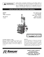


INSTALLATION AND OPERATION MANUAL
SHIPPING DAMAGE CLAIMS
When this equipment is shipped, title passes
to the purchaser upon receipt from the carrier.
Consequently, claims for the material damaged in
shipment must be made by the purchaser against
the transportation company at the time shipment is
received.
BE SAFE
Your new Ranger tire changer was designed and
built with safety in mind. However, your overall
safety can be increased by proper training and
thoughtful operation on the part of the operator.
DO NOT operate or repair this equipment
without reading this manual and the
important safety instructions shown inside.
1645 Lemonwood Dr.
Santa Paula, CA. 93060, USA
Toll Free: 1-800-253-2363
Tel: 1-805-933-9970
Fax: 1-805-933-9160
www.rangerproducts.com
PLEASE READ THE ENTIRE CONTENTS OF THIS MANUAL PRIOR TO
INSTALLATION AND OPERATION. BY PROCEEDING YOU AGREE THAT
YOU FULLY UNDERSTAND AND COMPREHEND THE FULL CONTENTS OF
THIS MANUAL. FORWARD THIS MANUAL TO ALL OPERATORS. FAILURE TO
OPERATE THIS EqUIPMENT AS DIRECTED MAY CAUSE INjURY OR DEATH.
REV D 04-20-11
PN# 5900157
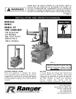
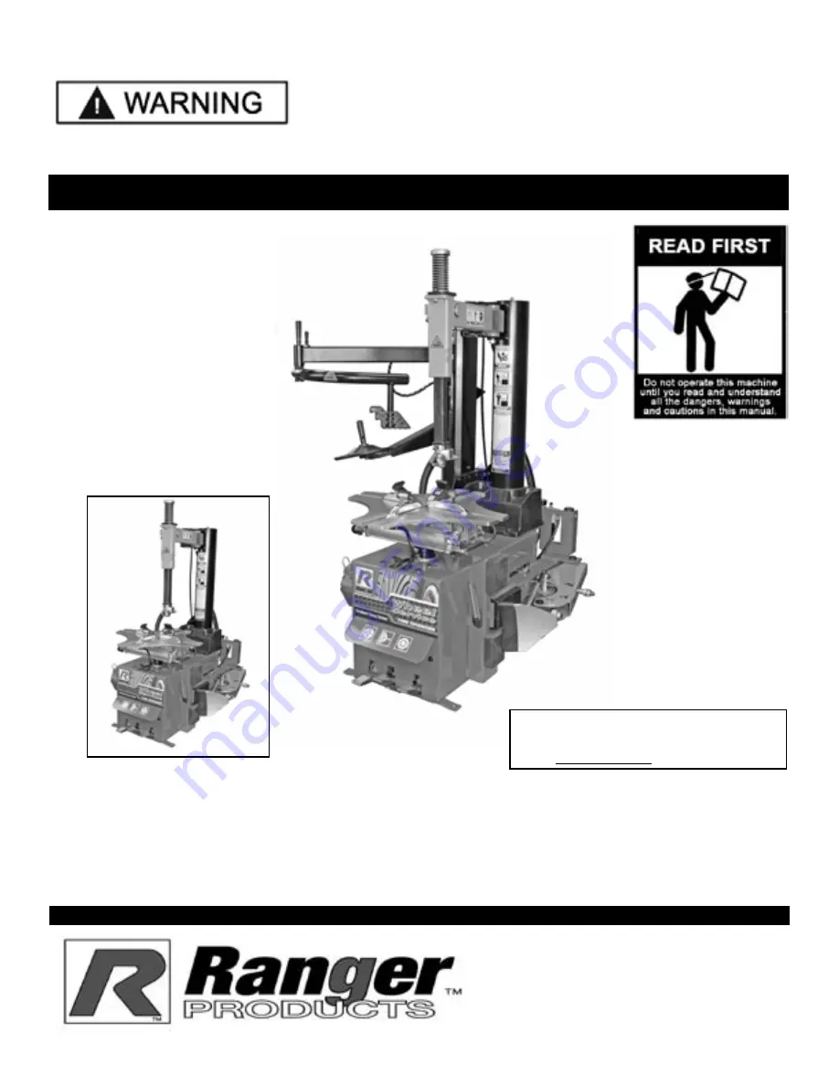
MODELS:
R980X
R980X- AT
TIRE CHANGER
FOR SERVICING
AUTOMOBILE
AND LIGHT TRUCk
SINGLE PIECE
TIRES / WHEELS
keep this operation manual near the
machine at all times. Make sure that
ALL USERS read this manual.
R980X-AT
R980X
Summary of Contents for R980X
Page 39: ...39 ...
Page 48: ...48 ...
Page 49: ...49 RECORD ALL MAINTENANCE NOTES AND SERVICE HISTORY HERE ...
Page 50: ...50 TIRE AND WHEEL DATA ...