background image

RANSOMES

¨

Parts and Maintenance Manual

Nomenclature Des Pieces De Rechange & Manuel De Maintenance

Onderhouds - En Onderdelenhandleiding

Sicherheits und Bedienungs anleitung

Manuale d’istruzioni per I’uso e la Sicurezza

RANSOMES

AVVERTENZA: Questa macchina può causare gravi infortuni
se viene utilizzata in modo errato. Prima di accingersi ad
approntare, usare, mettere a punto o eseguire la
manutenzione di questa macchina, coloro che la utilizzano
ed i responsabili della  manutenzione devono essere
addestrati all’impiego della macchina, devono essere informati
dei pericoli, e devono leggere l’intero manuale.

GB

GB

GB

GB

GB

Part No. 2812171-ML1 (rev.0)

(RJ 100 022001)

F

F

F

F

F

NL

NL

NL

NL

NL

D

D

D

D

D

IIIII

WARNHINWEIS: Wenn diese Maschine nicht ordnungsgemäß
verwendet wird, können ernsthafte Verletzungen verursacht
werden. Personen, die diese Maschine verwenden und
warten, müssen in ihrer richtigen Verwendung ausgebildet
sein, auf die Gefahren aufmerksam gemacht worden sein
und die Anleitung ganz gelesen haben, bevor sie versuchen,
die Maschine aufzustellen, zu bedienen, einzustellen oder
zu warten.

WAARSCHUWING: Bij verkeerd gebruik kan deze machine
ernstig lichamelijk letsel veroorzaken. Degenen die de ma-
chine gebruiken en onderhouden moeten worden getraind
in het juiste gebruik ervan, worden gewaarschuwd voor de
gevaren ervan en behoren de volledige handleiding
aandachtig te lezen alvorens de machine bedrijfs-klaar te
maken, te bedienen, af te stellen en/of te onderhouden.

AVERTISSEMENT : Risque de blessures graves en cas
d’utilisation incorrecte de la machine. Les opérateurs et le
personnel d’entretien doivent être formés et conscients des
dangers encourus. Ils doivent lire avec attention le manuel
avant d’essayer de monter, d’utiliser, de régler ou maintenir
la machine.

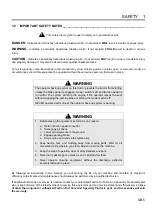
WARNING: If incorrectly used this machine can cause se-
vere injury.  Those who use and maintain this machine should
be trained in its proper use, warned of its dangers and should
read the entire manual before attempting to set up, operate,
adjust or service the machine.
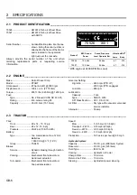
HR 9016 Turbo

4WD Product Number: 70526 - Engine type: Detroit Diesel D704LT
4WD with ROPS Product Number: 70527 - Engine type: Detroit Diesel D704LT

Summary of Contents for HR 9016 Turbo

Page 1: ...nz gelesen haben bevor sie versuchen die Maschine aufzustellen zu bedienen einzustellen oder zu warten WAARSCHUWING Bij verkeerd gebruik kan deze machine ernstig lichamelijk letsel veroorzaken Degenen...

Page 2: ...The Safety and Operation Manual must be kept in the pouch on the back of the seat at all times for reference by the operator Table of Contents 1 Safety 1 1 Operating Safety 4 1 2 Important Safety Not...

Page 3: ...789012 1 Valve Lift Includes Items 2 and 3 3 345678 1 Handle Serviced part included with Item 2 4 N S 1 Seal Kit Non serviced part included with Item 2 5 901234 2 1 Screw 1 4 20 x 2 Hex Head Indicate...

Page 4: ...t in perfect working order or is without decals guards shields discharge deflectors or other protective devices securely fastened in place 9 Never disconnect or bypass any switch 10 Carbon monoxide in...

Page 5: ...Authorized Textron Turf Care And Specialty Products Dealer who is kept informed of the latest methods to service this equipment and can provide prompt and efficient service Use of other than original...

Page 6: ...Type SAE 15 W40 API Classification CF 4 CD II CE Air Filter Dry type with evacuator valve and service indicator Alternator 55 amp 2 3 TRACTOR _________________________________________________________...

Page 7: ...te listing of accessories and attachments Air Blow Gun JAC5098 2 Post ROPS with Seat Belt 78138 All Weather Cab w ROPS and Seat Belt See Below Air Conditioner Kit See Below Leaf Mulching Kit 71055 Roa...

Page 8: ...ster tires is adjusted equally 3 Set desired cutting height of deck using the 1 2 13 mm spacers E provided See Section 3 5 4 Measure the height from the ground surface to the front edge B of the two o...

Page 9: ...el and caster wheels are just above ground Stop engine 3 Insert height adjustment pin for rear casters to match cutting height Figure 3F 4 Rotate anti sway mechanism F to it s operating position Figur...

Page 10: ...ove pin from rear gauge wheel yoke and reposition in bracket for desired height of cut When setting cutting height at 5 1 2 gauge wheel must be repositioned in arm Follow wheel mounting instructions o...

Page 11: ...The neutral adjustment on the drive pump is preset at the factory on all new tractors and replacement pumps Further adjustment is required only if the pump has been disassembled for service or neutral...

Page 12: ...erate in four wheel drive only with the traction pedal in its forward position When operating in reverse the switch opens and returns the tractor to two wheel drive If four wheel drive fails to operat...

Page 13: ...aise or lower decks until the highest point on the top corner of the deck reaches the height shown in Figure 3K 3 Shut off engine and remove key Support decks using blocks This will prevent them from...

Page 14: ...the forward position 1 Make sure return arm K Figure 3H on pump is adjusted to neutral Section 3 7 2 Push traction pedal forward I until it touches floor panel and hold in this position 3 Adjust turn...

Page 15: ...148 115 156 154 209 1 4 20 in lb Nm 75 8 4 100 11 3 107 12 1 143 16 1 9 16 18 ft lb Nm 92 124 122 165 129 174 172 233 1 4 28 in lb Nm 85 9 6 115 13 0 120 13 5 163 18 4 5 8 11 ft lb Nm 113 153 151 204...

Page 16: ...eration or whenever mower is removed from tractor carefully examine the blades to make sure they are in good operating condition Blades showing any bends G grooves H or cracks J must be replaced 2 Any...

Page 17: ...ive vibration and may damage the mower 4 Use a blade balancer to check the blade after sharpening 5 Attach blade to mower Install blades so cutting edges C face the direction of rotation as shown in F...

Page 18: ...nce intervals and procedures If the injection pump injectors or the fuel system require service contact an authorized Textron Turf Care And Specialty Products Dealer Note The tractor is designed to op...

Page 19: ...igure 4E 4 8 FUEL ____________________________________________________________________ Handle fuel with care it is highly flammable Use an approved container the spout must fit inside the fuel filler...

Page 20: ...g or disconnecting the battery cables 1 When installing the battery always assemble the RED positive battery cable first and the ground BLACK negative cable last 2 When removing the battery always rem...

Page 21: ...necting any hydraulic component clean the area around the fittings and the hose ends to keep impurities out of the system a Before disconnecting any hydraulic component tag or mark the location of eac...

Page 22: ...protected by two 10 micron filters a charge filter B and return line filter A Flow though the filters is monitored during operation When pressure drop across the filters is too high the hydraulic oil...

Page 23: ...ow out from back side using compressed air Oil Cooler and Radiator Inspect oil cooler and radiator daily and clean as required to maintain good air flow 1 Remove screen B from front of oil cooler 2 Un...

Page 24: ...properly secured 2 Check the operator backup system fuses and circuit breakers regularly If the operator backup system does not function properly and the problem cannot be corrected contact an authori...

Page 25: ...cuit Relay closes when traction pedal is in neutral NT2 K7 Neutral Run Disconnects power to the fuel stop solenoid valve when operator leaves seat with neu tral switch still open traction pedal presse...

Page 26: ...lbs 88 102 Nm Caster Wheels To extend bearing life check and adjust caster and gauge wheels every year Lubricate bearings every 100 hours using NLGI Grade 2 grease 1 Raise deck so wheels are off groun...

Page 27: ...ttery in upright position in a cool dry place 2 Check and recharge battery every 60 to 90 days while in storage 3 Store batteries in a cool dry place To reduce the self discharge rate room temperature...

Page 28: ...68 WARNING Before you clean adjust or repair this equipment disengage all drives lower implements to the ground engage parking brake stop engine and remove key from ignition switch to prevent injuries...

Page 29: ...Spindles 10 2 Caster Wheel Axles 10 3 Gauge Wheel Axles 2 4 Lift Cylinder Front Deck 4 5 Lift Arm Front Deck 2 6 Side Deck Pivots 6 7 Steering Cylinder 2 8 Tie Rod 2 9 Axle Pivot 1 10 Wheel Pivot 2 1...

Page 30: ...hard to start or runs poorly 1 Fuel level low fuel or fuel filter dirty 1 Fill with fresh fuel Change fuel filter Bleed fuel lines 2 Air cleaner dirty 2 Inspect and replace air filter 3 Injectors fue...

Page 31: ......

Page 32: ...ement 4 1 2 Consignes de s curit importantes 5 2 Sp cifications 2 1 Identification du produit 6 2 2 Moteur 6 2 3 Tracteur 6 2 4 Poids dimensions 7 2 5 Unit s de coupe 7 2 6 Accessoires documents d ass...

Page 33: ...ses pour obtenir un r glage correct Symboles Ex pr s du num ro de l article renvoie une explication suppl mentaire importante pour passer commande El ments num r s Les pi ces pr c d es d un point en r...

Page 34: ...e vous servez jamais d une machine qui ne dispositifs de protection d flecteurs de d versement ou tout autre dispositif de s curit manquent sont mal positionn s ou desserr s 9 Ne d branchez et ne pass...

Page 35: ...renseignements compl mentaires ou services d entretien suppl mentaires car il est au courant des toutes derni res techniques et r pondra rapidement vos demandes La garantie est annul e en cas d utili...

Page 36: ...aissage Volume 7 qts Type SAE 15W40 Cat gorie API CF 4 CD II CE Filtre air Type sec avec vacuateur et indicateur d utilisation Alternateur 55 A 2 3 TRACTEUR____________________________________________...

Page 37: ...ment 2 montants avec ceinture de s curit 78138 Cabine tout temps avec protection au retournement et ceinture de s curit voir plus bas Kit climatisation voir plus bas Kit de paillage 71055 Kit de feux...

Page 38: ...z que la pression d air dans les pneus de toutes les roues est la m me 3 R glez la hauteur de coupe souhait e du plateau en utilisant les entretoises 13 mm E fournies Voir le Chapitre 3 5 4 Quand il s...

Page 39: ...ge de hauteur de coupe du support de roue de r f rence de mani re ce que la chape flotte librement 4 D marrez le moteur et levez le plateau sa position haute Arr tez le moteur 5 Soulevez la main l ava...

Page 40: ...ir du sol au bord avant de la partie centrale de la lame du plateau avant B puis aux bords ext rieurs des lames des plateaux lat raux L Ajoutez ou retirez s il y a lieu des cales G entre le patin H et...

Page 41: ...s rondelles de but e minces 1 5 mm ni les rondelles de mise niveau 3 mm sur l axe Ces rondelles doivent rester au m me emplacement et la quantit install e l origine Elles ont uniquement besoin d tre r...

Page 42: ...ini en usine sur tous les tracteurs neufs et les pompes de rechange Tout r glage ult rieur n est requis que si la pompe a t d mont e la suite d un service d entretien ou si le support F du levier de f...

Page 43: ...tion est dans sa position avant En marche arri re le contacteur s ouvre et ram ne le tracteur en deux roues motrices Si le mode quatre roues motrices ne marche pas contr lez le r glage et le fonctionn...

Page 44: ...rieur du plateau atteigne la hauteur illustr e au Sch ma 3K 3 Coupez le moteur et enlevez la cl de contact Reposez les plateaux sur des cales Cela vitera qu ils ne s abaissent accidentellement lorsqu...

Page 45: ...e retour K Sch ma 3H sur la pompe soit r gl au neutre Chapitre 3 7 2 Poussez la p dale de traction vers l avant I jusqu ce qu elle touche le panneau de sol et maintenez la dans cette position 3 R glez...

Page 46: ...6 7 85 115 90 122 120 162 12 24 in lb Nm 50 5 7 65 7 3 9 16 12 ft lb Nm 82 111 109 148 115 156 154 209 1 4 20 in lb Nm 75 8 4 100 11 3 107 12 1 143 16 1 9 16 18 ft lb Nm 92 124 122 165 129 174 172 233...

Page 47: ..._________________________ 1 V rifiez les lames toutes les 50 heures de service ou quand les unit s de coupe sont d pos es de la machine Veillez toujours ce qu elles fonctionnent correctement Remplacez...

Page 48: ...l aff tage termin utilisez une jauge d quilibrage 5 Fixez la lame l unit de coupe Placez les lames de fa on ce que leurs bords tranchants C fassent face au sens de rotation Sch ma 4C Les bords trancha...

Page 49: ...injecteurs ou le circuit carburant n cessitent un service d entretien adressez vous au concessionnaire agr Textron Turf Care And Specialty Products Remarque La machine fonctionne et tond efficacement...

Page 50: ...________________________________ Attention au carburant car il est tr s inflammable Utilisez un r cipient adapt dont le bec arrive s introduire l int rieur du goulot de remplissage de carburant Evitez...

Page 51: ...la polarit de la batterie avant de brancher ou d brancher ses c bles 1 Quand vous installez la batterie placez toujours en premier son c ble positif ROUGE puis son c ble terre et en dernier son c ble...

Page 52: ...cuit hydraulique quand l huile est contamin e Avant de d brancher les composants hydrauliques nettoyez la surface environnant leurs raccords et les extr mit s des flexibles pour liminer les impuret s...

Page 53: ...t traversant les filtres est toujours contr l lors du fonctionnement Lorsqu une chute de pression est trop forte pour les filtres le voyant du filtre huile hydraulique s allume Afin de prot ger d une...

Page 54: ...re Refroidisseur d huile et radiateur Inspectez tous les jours le refroidisseur d huile et le radiateur et nettoyez au besoin pour maintenir une bonne circulation d air 1 D posez le tamis B de l avant...

Page 55: ...ques et les endommage ou les met en panne pr matur ment Ce genre d endommagement n est pas couvert par la garantie 3 Ne vaporisez pas d eau sur le pupitre des instruments la cl de contact le variateur...

Page 56: ...e 6 Ne nettoyez pas les surfaces environnantes des raccordements et composants lectriques Les circuits sont prot g s par un disjoncteur situ au dessus des batteries ainsi que des fusibles et des relai...

Page 57: ...raction est au neutre NT2 K7 Neutre Marche D branche l alimentation lectrique de l lectrovalve de coupure du carburant quand l op rateur quitte son si ge avec le contacteur de neutre toujours ouvert p...

Page 58: ...Nm Roues pivotantes Pour prolonger la dur e de vie des roulements contr lez et r glez tous les ans l tat des roues pivotantes et des roues de r f rence Lubrifiez les roulements toutes les 100 heures e...

Page 59: ...s r guli rement et regonflez les s il y a lieu 5 Veillez ce que la machine et ses accessoires restent propres secs et prot g s contre les intemp ries pendant l entreposage Ne l entreposez jamais pr s...

Page 60: ...circuit carburant et remplissez le avec du carburant neuf 6 Veillez ce que les pneus soient bien gonfl s 7 Eliminez toute l huile des cylindres et de la contrelame Ajustez la contrelame et la hauteur...

Page 61: ...are And Specialty Products VG ISO 68 AVERTISSEMENT Avant de nettoyer r gler ou r parer ce mat riel d brayer tous les entra nements abaisser les accessoires au sol serrer le frein de stationnement arr...

Page 62: ...ieux de roue de r f rence 2 4 V rin de levage plateau avant 4 5 Bras de levage plateau avant 2 6 Pivots de plateau lat ral 6 7 V rin de direction 2 8 Barre d accouplement 2 9 Pivot d essieu 1 10 Pivot...

Page 63: ...1 Bas niveau de carburant car burant ou filtre carburant sale 1 Remplir de carburant neuf Remplacer le filtre carburant et purger les conduites carburant moteur 2 L purateur d air est sale 2 V rifier...

Page 64: ...tie ongeldig Inhoudsopgave 1 Veiligheid 1 1 Operationele veiligheid 4 1 2 Belangrijke veiligheidsoverwegingen 5 2 Specificaties 2 1 Productidentificatie 6 2 2 Motor 6 2 3 Tractor 6 2 4 Gewichten en af...

Page 65: ...ling te bereiken Symbolen zoals naast het itemnummer geven aan dat er een opmerking is opgenomen met aanvullende informatie die belangrijk is bij het bestellen van dat onderdeel Items met bullet point...

Page 66: ...drijf sstaat verkeert geen decalplaatjes heeft of waarvan de beschermkappen keerschotten en of andere beveilig ingsinrichtingen niet of onvoldoende stevig zijn bevestigd 9 Geen enkele schakelaar mag o...

Page 67: ...er Onze dealers worden op de hoogte gehouden van de nieuwste onderhoudsmethoden ten behoeve van deze machines en kunnen een snelle en effici nte service verlenen Gebruik van andere dan originele en go...

Page 68: ...CF 4 CD II CE Luchtfilter Droog type met vacu mklep en service indicator Wisselstroomdynamo 55 Amp 2 3 TRACTOR ________________________________________________________________ Banden Voor 29 x 14 15...

Page 69: ...78138 Weerbestendige cabine met ROPS en veiligheidsriem zie onderstaand Airconditioning set zie onderstaand Bladmulch set 71055 Wegverlichtingsset vereist 5003564 78154 Werkverlichtingsset vereist 500...

Page 70: ...ielbanden gelijk is 3 Stel de gewenste maaihoogte van de dekken in met behulp van de meegeleverde 13 mm afstandss tukken E Zie sectie 3 5 4 Meet de hoogte vanaf het grondoppervlak tot de voorrand B va...

Page 71: ...zich iets boven de grond bevinden Zet de motor stil 3 Breng een hoogte afstelpen in om de achterste zwenkwielen aan te passen aan de maaihoogte afb 3F 4 Draai het anti slinger mechanisme F naar de be...

Page 72: ...rukschijven 1 5 mm en de nivelleerpakkingen 3 mm niet op de spindel maar houd hetzelfde aantal in dezelfde stand zoals oorspronkelijk ge nstalleerd Herpositionering kan alleen nodig zijn om nieuwe zwe...

Page 73: ...alstand op de drijfpomp is een fabrieksinstelling die geldt voor alle nieuwe tractors en vervangingspompen Verdere bijstelling is alleen vereist als de pomp voor onderhoud is gedemonteerd of als de ne...

Page 74: ...e vooruitstand staat Bij achteruitrijden opent de schakelaar en keert de tractor terug naar tweewielaandrijving Indien de vierwielaandrijving niet functioneert controleer dan de afstelling en werking...

Page 75: ...p de bovenste hoek ervan de hoogte bereikt die in Afb 3K is aangegeven 3 Zet de motor stil en verwijder de contactsleutel Ondersteun de dekken met blokken om accidentele verlaging tijdens het uitvoere...

Page 76: ...van vooruitrijden 1 Zorg ervoor dat de retourarm K Afb 3H op de pomp in neutraal staat sectie 3 7 2 Druk de tractiepedaal naar voren I tot hij het vloerpaneel raakt en houd hem daar in positie 3 Stel...

Page 77: ...0 ft lb Nm 64 86 7 85 115 90 122 120 162 12 24 in lb Nm 50 5 7 65 7 3 9 16 12 ft lb Nm 82 111 109 148 115 156 154 209 1 4 20 in lb Nm 75 8 4 100 11 3 107 12 1 143 16 1 9 16 18 ft lb Nm 92 124 122 165...

Page 78: ...zorgvuldig worden onderzocht om er zeker van te zijn dat ze operationeel in goede conditie verkeren Messen die verbuigingen G groeven H of scheurtjes J vertonen moeten worden vervangen 2 Ieder van bov...

Page 79: ...e machine beschadigen 4 Gebruik een mesbalanceerinrichting ter controle van de symmetrie na het aanscherpen 5 Bevestig de messen weer aan de maaimachine en installeer ze zodanig dat de snijranden C in...

Page 80: ...mp inspuitstukken of het brandstofsysteem service nodig hebben neem dan contact op met een erkende Textron Turf Care And Specialty Products Dealer N B De tractor is ontworpen om optimaal te werken en...

Page 81: ...s en verwijder daarna het oude element zo voorzichtig mogelijk 1 Maak de binnenkant van het filterhuis zorgvuldig schoon ervoor zorgend dat er geen stof in de luchtinlaat komt 2 Inspecteer het nieuwe...

Page 82: ...ordeningen en de aanbevelingen van uw brandstofleverancier De tank mag nooit worden overvuld of geheel leeg raken In de Motorhandleiding vindt u aanvullende brandstofinformatie WAARSCHUWING Zolang de...

Page 83: ...aansluiten of loskoppelen van de accukabels 1 Bij het installeren van de accu moet altijd eerst de RODE positieve accukabel worden bevestigd en de ZWARTE negatieve aardingskabel het laatst 2 Bij verw...

Page 84: ...om vreemde stoffen uit het systeem te houden a Alvorens een hydraulisch onderdeel los te kop pelen dient de locatie van iedere slang te worden gemerkt waarna het gedeelte rond de bevestigingen moet wo...

Page 85: ...ulisch systeem wordt beschermd door twee 10 micron filters een laadfilter B en een terugleidingfilter A De stroming door de filters wordt tijdens de operationele werking gecontroleerd Wanneer de drukd...

Page 86: ...ateur Inspecteer de oliekoeler en de radiateur dagelijks en maak ze waar nodig schoon om een goede luchtstroming te handhaven 1 Verwijder de grille B van de voorkant van de olieko eler 2 Zet de knoppe...

Page 87: ...d in voortijdige achteruitgang of defecten Dergelijke beschadiging wordt niet gedekt door de fabrieksgarantie 3 Spuit geen water rechtstreeks op het instrumenten paneel de ontstekingsschakelaar de con...

Page 88: ...stroomcircuit 6 Rond elektrische aansluitingen en componenten mag niet worden gewassen noch een drukspuit worden gebruikt Circuits worden beveiligd door een contactverbreker boven de accu geplaatst pl...

Page 89: ...7 Neutraal Aan Schakelt de stroom naar de elektromagnetische brandstofstopklep uit wanneer de bestuurder de zitplaats verlaat met de neutraalschakelaar nog open tractiepedaal ingedrukt NT3 K8 Neutraal...

Page 90: ...jaar worden gecontroleerd en bijgesteld Smeer de lagers na iedere 100 bedrijfsuren met NLGI kwaliteit 2 vet 1 Breng het dek zover omhoog dat de wielen los van de grond zijn en vrijelijk met de hand k...

Page 91: ...breng ze waar nodig opnieuw op spanning 5 Houd de machine en alle accessoires tijdens de stalling schoon droog en beschermd tegen het weer Stal de uitrusting nooit nabij een open vlam of mogelijke von...

Page 92: ...eem 5 Vul de brandstoftank met verse brandstof Ontlucht het brandstofsysteem 6 Zorg ervoor dat de banden de juiste spanning hebben 7 Verwijder alle olie van de kooimessen en het ondermes Stel het onde...

Page 93: ...8 WAARSCHUWING Alvorens te beginnen met schoonmaken afstellen of reparatie van deze machine dienen alle andrijvingen te worden uitgeschakeld de aanzetstukken op de grond te worden neergelaten en de pa...

Page 94: ...wielspindels 10 2 Zwenkwielassen 10 3 Spoorwielassen 2 4 Hefcilinder voorste dek 4 5 Hefarm voorste dek 2 6 Zijdekdraaipennen 6 7 Stuurcilinder 2 8 Trekstang 2 9 Asdraaipen 1 10 Wieldraaipen 2 11 Hefa...

Page 95: ...Laag brandstofniveau brand stof of brandstoffilter vervuild 1 Vullen met verse brandstof Vervang het brandstoffilter Ontlucht de brandstofleidingen 2 Vuil luchtfilter 2 Inspecteer en vervang het lucht...

Page 96: ...elassenen Teilen macht die Garantie ung ltig Inhalt 1 Sicherheit 1 1 Betriebssicherheit 4 1 2 Wichtige Hinweise zur Sicherheit 5 2 Technische Daten 2 1 Produktidentifizierung 6 2 2 Motor 6 2 3 Traktor...

Page 97: ...derlich um die richtige Einstellung zu erhalten Symbole wie neben der Artikelnummer bedeuten da ein Hinweis vorhanden ist der zus tzliche zur Bestellung des Artikels wichtige Informationen enth lt Mit...

Page 98: ...Schutzvorrichtungen Abschirmungen Auswurfabweiser oder andere Schutzvorrichtungen sicher angebracht hat 9 Niemals Schalter abschalten oder umgehen 10 Das Kohlenmonoxid in den Auspuffgasen kann beim I...

Page 99: ...mationen oder Dienstleistungen erforderlich sind wenden Sie sich bitte an Ihren zugelassenen Vertragsh ndler von Textron Turf Care And Specialty Products der ber die neuesten Methoden zum Instandhalte...

Page 100: ...gen 7 qts Typ SAE 15 W40 API Klassifizierung CF 4 CD II CE Luftfilter Trockenfilter mit Entl fterventil und Wartungsanzeige Lichtmaschine 55 Ampere 2 3 TRAKTOR ________________________________________...

Page 101: ...Luftpistole JAC5098 2 Pfosten ROPS mit Sicherheitsgurt 78138 Allwetterkabine mit ROPS und Sicherheitsgurt siehe unten Klimanalagensatz siehe unten Blattmulchersatz 71055 Stra enlampensatz erfordert 5...

Page 102: ...n 4 Nicht die Reglereinstellungen ndern oder den Motor mit zu hoher Drehzahl betreiben ACHTUNG Vor der Durchf hrung von Einstellungen oder Wartungsarbeiten die Vorrichtungen auf den Boden senken alle...

Page 103: ...llel zum Traktor in Position bringen 2 Pr fen da der Reifendruck in allen Schwenkra dreifen gleich ist 3 Unter Verwendung der mitgelieferten 13mm Abstandst cke E die gew nschte Schnitth he der Schneid...

Page 104: ...schalten 3 Die Schnitth heneinstellstifte von der Radstelzen halterung entfernen damit die Jocheinheit frei schwebt 4 Den Motor einschalten und die Vorrichtung in die oberste Position anheben Den Moto...

Page 105: ...die H he vom Erdboden zur Vorderkante des mittleren Blattes am Vorderdeck B und den u eren Kanten der Bl tter auf den Auslegern L Setzen Sie je nach Bedarf zwischen der Unterlage H und den Befestigung...

Page 106: ...dsst cke einstellen Zus tzliche Abstandsst cke oben auf der Spindel lagern Soweit erforderlich die Radhalterung in den f r die Schnitth he angezeigten L chern neu positionieren WICHTIG Die d nnen Druc...

Page 107: ...arten und das Bedienerbackupsystem funktioniert nicht korrekt Zur Nachstellen des Schalters 1 Die Feststellbremse in ihre ganz aufrechte angezo gene Position bringen 2 Den Schalter C durch Drehen der...

Page 108: ...nach unten auf den Metallrahmen legen 6 Den Motor anlassen und die R der beobachten Die Klammer F in den Schlitzl chern rotieren bis die R der sich nicht drehen Den Motor abstellen und die Klammer in...

Page 109: ...und 3 8 2 Den Schalter so einstellen da der Abstand zwischen der Sensorfl che am Schalter und der Kante der Ausl serplatte zwischen 1 5 3mm ist 3 Den Schalter vom Kabelbaum trennen und ber die Schalt...

Page 110: ...ste Stelle an der oberen Ecke der Vorrichtung die auf Abbildung 3K angezeigte H he erreicht 3 Den Motor abschalten und den Z ndschl ssel herausziehen Die Vorrichtung durch Bl cke abst tzen Hierdurch w...

Page 111: ...R ckf hrarm K Abb 3H an der Pumpe auf neutral eingestellt ist Abschnitt 3 7 2 Das Fahrpedal nach vorne niederdr cken I bis es die Bodenplatte ber hrt und in dieser Position halten 3 Die Spannschraube...

Page 112: ...22 120 162 12 24 in lb Nm 50 5 7 65 7 3 9 16 12 ft lb Nm 82 111 109 148 115 156 154 209 1 4 20 in lb Nm 75 8 4 100 11 3 107 12 1 143 16 1 9 16 18 ft lb Nm 92 124 122 165 129 174 172 233 1 4 28 in lb N...

Page 113: ...ird sind die Klingen sorgf ltig zu berpr fen um sicherzustellen da sie in einem guten Betriebszustand sind Klingen die Kr mmungen G Rillen H oder Risse J aufweisen m ssen ausgewechselt werden 2 Jede d...

Page 114: ...Schleifen eine Klingenausgleichsvorrichtung verwenden 5 Die Klinge an der M hvorrichtung anbringen Die Klingen so anbringen da die Schneidkanten C in Drehrichtung zeigen wie in Abb 4C gezeigt Abgesch...

Page 115: ...em gewartet werden m ssen wenden Sie sich bitte an einen zugelassenen Vertragsh ndler von Textron Turf Care And Specialty Products Hinweis Der Traktor ist so konstruiert da er bei der Voreinstellung d...

Page 116: ...tig handhaben da er leicht entz ndlich ist Einen zugelassenen Container verwenden dessen Schnabel in den Tankeinf llstutzen passen mu Zum Umf llen des Kraftstoffs keine Dosen und Trichter verwenden De...

Page 117: ...die Batteriekabel angeschlossen oder getrennt werden 1 Beim Anbringen der Batterie immer zuerst das ROTE positive Batteriekabel und zuletzt das SCHWARZE negative Erdungskabel anbringen 2 Beim Entfern...

Page 118: ...d die Schlauchenden herum reinigen damit keine Fremdk rper in das System eindringen a Vor dem Trennen irgendwelcher Hydraulikko mponenten den Platz eines jeden Schlauchs markieren dann den Bereich um...

Page 119: ...tem wird durch zwei Filter mit 10 Mikron gesch tzt dem Hauptstromfilter B und R ckleitungsfilter A W hrend des Betriebs wird der Durchflu durch die Filter berwacht Wenn der Druckabfall quer ber die Fi...

Page 120: ...nten mit Druckluft durchblasen lk hler und K hler Den lk hler und K hler t glich berpr fen und nach Bedarf reinigen um einen guten Luftstrom zu erhalten 1 Den Grill B vorne am K hler abnehmen 2 Die Kn...

Page 121: ...osion der Metallteile wodurch Abnutzungserscheinungen oder St rungen vorzeitig auftreten Sch den dieser Art sind von der Werksgarantie ausgeschlossen 3 Wasser nicht direkt auf das Instrumentenbrett de...

Page 122: ...lossen ist 5 Die Batterie und den Batterieladekreis pr fen 6 Die elektrischen Anschl sse und Komponenten nicht waschen oder unter Druck abspritzen Die Schaltkreise werden durch einen Leistungsschalter...

Page 123: ...st NT2 K7 Neutral Betrieb Unterbricht den Strom zum Kraftstoffventil wenn der Bediener seinen Platz verl t wenn der Neutralschalter noch offen ist Fahrpedal gedr ckt NT3 K8 Neutral Fahrt Unterbricht d...

Page 124: ...der Lager die Schwenkr der und Radstelzen j hrlich berpr fen Die Lager alle 100 Stunden unter Verwendung von Fett NLGI Klasse 2 schmieren 1 Die Schneidvorrichtung anheben damit sich die R der vom Bod...

Page 125: ...gen Abst nden gepr ft und soweit erforderlich Luft nachgef llt werden 5 Die Maschine und das gesamte Zubeh r an einem sauberen trockenen und vom Wetter gesch tzten Ort lagern Die Ausr stung niemals in...

Page 126: ...nk mit frischem Kraftstoff auff llen Das Kraftstoffsystem entl ften 6 Sicherstellen da die Reifen richtig mit Luft gef llt sind 7 Alles l von den Schneidzylindern und vom Grundmesser entfernen Das Gru...

Page 127: ...And Specialty Products Hydraulik l VG ISO 68 ACHTUNG Vor dem Reinigen Einstellen oder Reparieren dieser Ausr stung alle Antriebe l sen die Vorrichtungen auf den Boden senken die Feststellbremse anzieh...

Page 128: ...dstelzenachsen 2 4 Hubzylinder vordere Schneidvorrichtung 4 5 Hubarm vordere Schneidvorrichtung 2 6 Schenkel seitliche Schneidvorrichtungen 6 7 Lenkzylinder 2 8 Zugstange 2 9 Achselschenkel 1 10 Radsc...

Page 129: ...Das Kraftstoffilter auswech seln Die Kraftstoffleitungen entl ften 2 Das Luftfilter ist verschmutzt 2 Das Luftfilter pr fen und auswechseln 3 Einspritzd sen Kraft stoffpumpe 3 Das Handbuch f r den Mo...

Page 130: ...2 2 Motore 6 2 3 Trattore 6 2 4 Dimensioni e peso 7 2 5 Gruppo di falciatura 7 2 6 Accessori e documentazione a supporto 7 3 Regolazioni 3 1 Dati generali 8 3 2 Livellamento dei gruppi di falciatura...

Page 131: ...r ottenere la regolazione corretta Il simboli accanto al numero del ricambio indica la presenza di una nota contenente ulteriori informazioni utile per l ordinazione di quel ricambio Elementi precedut...

Page 132: ...in perfette condizioni di funzionamento o prive di decalcomanie ripari schermi deflettori di scarico o altri dispositivi protettivi fissati correttamente in posizione 9 Non disconnettere n bipassare m...

Page 133: ...enti per mantenere questo apparecchio ed in grado di fornire l assistenza pronta ed efficiente ai clienti L uso di ricambi e accessori non originali Textron Turf Care And Specialty Products annulla la...

Page 134: ...ficazione API CF 4 CD II CE Filtro aria A secco con valvola di evacuazione e spia di servizio Alternatore 55 A 2 3 TRATTORE_______________________________________________________________ Pneumatici An...

Page 135: ...98 Gabbia antiribaltamento ROPS 2 posti con cinture di sicurezza 78138 Cabina ognitempo con gabbia antiribaltamento ROPS e cinture di sicurezza vedere in basso Condizionatore d aria vedere in basso Gr...

Page 136: ...ssa 3 Impostare l altezza di taglio desiderata servendosi degli spaziatori da 13 mm E in dotazione Vedere la Sezione 3 5 4 Misurare l altezza dal suolo a partire dalla superficie del suolo al bordo an...

Page 137: ...siano livellate e le rotelle sfiorino appena il suolo Spegnere il motore 3 Inserire il fermo di regolazione dell altezza di taglio nelle rotelle posteriori in modo da allinearle come in Figura 3F 4 Ru...

Page 138: ...ondelle dovrebbero rimanere nella stessa posizione e della stessa quantit in cui sono state originariamente installate La loro posizione pu eventualmente essere corretta solo qualora si debbano livell...

Page 139: ...nuovi e le pompe in sostituzione la pompa di azionamento preregolata in fabbrica su neutro Occorre una ulteriore regolazione soltanto nel caso in cui la pompa sia stata smontata a scopo di assistenza...

Page 140: ...solo quando il pedale della trazione in posizione di marcia in avanti In retromarcia l interruttore si apre e riporta il trattore sulla trazione a due ruote motrici Se la trazione a quattro ruote motr...

Page 141: ...golo superiore delle bobine non raggiunge l altezza indicata nella Figura 3K 3 Spegnere il motore e togliere la chiave Puntellare le bobine in modo da evitare che possano abbassarsi accidentalmente du...

Page 142: ...orno K Figura 3H sulla pompa sia regolato su neutro come indicato nella Sezione 3 7 2 Spingere in avanti il pedale della trazione I fino a fargli toccare il pannello sul pianale e tenerlo in questa po...

Page 143: ...m 50 5 7 65 7 3 9 16 12 ft lb Nm 82 111 109 148 115 156 154 209 1 4 20 in lb Nm 75 8 4 100 11 3 107 12 1 143 16 1 9 16 18 ft lb Nm 92 124 122 165 129 174 172 233 1 4 28 in lb Nm 85 9 6 115 13 0 120 13...

Page 144: ...ciatrice dal trattore esaminare attentamente le lame per assicurarsi che siano in buone condizioni di funzionamento Sostituire le lame che presentino piegature G solchi H o incrinature J 2 Una lama ch...

Page 145: ...bilanciamento della lama con un bilanciatore 5 Collegare la lama alla falciatrice Montare le lame in modo che il filo C sia rivolto secondo il senso di rotazione come indicato nella Figura 4C Il filo...

Page 146: ...tema del carburante richiedono la manutenzione rivolgersi ad un Concessionario Textron Turf Care And Specialty Products NB Il trattorino progettato per funzionare e per tosare nel modo pi efficiente a...

Page 147: ...il carburante con attenzione perch altamente infiammabile Usare un contenitore autorizzato provvisto di becco inseribile all interno del bocchettone del serbatoio Non usare lattine n imbuti per trasfe...

Page 148: ...a di collegare o scollegare i cavi della batteria 1 Quando si installa la batteria montare sempre il cavo ROSSO positivo della batteria per primo e il cavo NERO negativo di massa per ultimo 2 Quando s...

Page 149: ...o ai fissaggi e alle estremit dei tubi flessibili per impedire l ingresso di impurezze nel sistema a Prima di disconnettere qualsiasi componente idraulico contrassegnare o marcare la posizione di cias...

Page 150: ...filtro di carica B e il filtro sulla linea di ritorno A Durante il funzionamento viene controllato il flusso attraverso i filtri e quando la caduta di pressione tra i filtri eccessiva si accende la s...

Page 151: ...re e refrigeratore dell olio Controllare quotidianamente radiatore e refrigeratore dell olio e se necessario pulirli per mantenere un adeguato flusso d aria 1 Togliere il filtro B dalla parte frontale...

Page 152: ...precoce o di guasti Danni di tal natura non sono coperti dalla garanzia di fabbrica 3 Non spruzzare l acqua direttamente sul quadro degli strumenti l interruttore d accensione il controllore o qualsia...

Page 153: ...Controllare la batteria e il circuito di caricamento della batteria 6 Non lavare n pulire con nebulizzatori a pressione attorno ai raccordi e ai componenti elettrici I circuiti sono protetti da un int...

Page 154: ...Avviamento Parte del circuito di avviamento Il rel si chiude quando il pedale della trazione in folle NT2 K7 Folle Marcia Toglie alimentazione all elettrovalvola che determina l arresto del flusso di...

Page 155: ...i controllare e regolare le ruote orientabili e quelle di calibrazione ogni anno Lubrificare i cuscinetti ogni 100 ore di funzionamento con grasso NLGI Grado 2 1 Sollevare le bobine in modo che le ruo...

Page 156: ...l mon taggio e qualsiasi altro accessorio del ROPS deb bono essere ispezionati regolarmente e tutte le parti danneggiate essere immediatamente sostituite 2 Se il ROPS subisce un qualunque tipo di impa...

Page 157: ...olio dalla coppa e cambiare il filtro dell olio Installare il tappo di scarico e riempire con olio fresco Applicare sul tappo una coppia di 30 Nm 2 Pulire l esterno del motore Verniciare il metallo e...

Page 158: ...lico Textron Turf Care And Specialty Products VG ISO 68 AVVISO Prima di pulire regolare o riparare questa apparecchiatura disinnestare tutti i comandi innestare il freno di stazionamento arrestare il...

Page 159: ...librazione 2 4 Cilindro di sollevamento Bobine anteriori 4 5 Braccio di sollevamento Bobine anteriori 2 6 Perni bobine laterali 6 7 Cilindro dello sterzo 2 8 Tirante 2 9 Perno dell assale 1 10 Perno d...

Page 160: ...o fil tro carburante sporco 1 Riempire con carburante nuovo sostituire il filtro carburante spurgare i condotti del carburante stento 2 Filtro aria sporco 2 Controllare e sostituire il filtro 3 Iniet...

Page 161: ...SOLUZIONE DEI PROBLEMI 5 I 33...

Page 162: ......

Page 163: ...ift Cylinders and Return Canisters 84 30 1 Front Deck Valves 86 31 1 Wing Deck Valves 87 Hydraulics and Electrical 32 1 Side Deck Valve Supply 88 33 1 Front Deck Valve Supply 89 34 1 Pump Supply 90 35...

Page 164: ...IGNITION TO OFF POSITION AND REMOVE KEY 1 DECK LATCHES DISENGAGED 2 CUTTING UNITS LOWERED 3 FOUR WHEEL DRIVE SWITCH ON 4 PTO SWITCH ON 5 PARKING BRAKE OFF 6 THROTTLE POSITION 1 7 DEPRESS TRACTION PEDA...

Page 165: ...E WARNING Daily Service Instructions Read manual thoroughly before operating for maintenance instructions Maintain fluid level in radiator recovery tank between Full and Low mark when engine is cold C...

Page 166: ...34 HR 9016 2 1 Hood Serial No All 9016 21 1 2 3 4 5 6 7 8 9 10 12 13 14 15 16 17 18 19 20 7 7 7 8 8 8 7 16 17 11 11 21 21...

Page 167: ...r 3 8 7 446142 14 Lockwasher 3 8 Heavy 8 443110 12 Nut 3 8 16 Hex 9 354989 2 Stop Rubber 10 443112 2 Nut 3 8 24 Hex 11 444310 8 Nut 10 24 Hex 12 340795 1 Handle Hood 13 402230 2 Screw 1 4 20 x 1 Slott...

Page 168: ...36 A B C A B C HR 9016 3 1 Cowlings and Skirts Serial No All 9016 24 1 2 3 4 5 6 7 8 9 10 11 12 13 14 15 16 17 18 19 20 1 2 5 5 6 6 7 7 8 8 9 11 16 17 19...

Page 169: ...3007704 8 Stud 85 1 4 Turn 8 3005603 8 Retainer 9 443110 8 Nut 3 8 16 Hex 10 3006915 4 Bracket Cowling Mounting 11 446142 8 Lockwasher 3 8 Heavy 12 3006723 1 Left Side Skirt 13 3006724 1 Right Side S...

Page 170: ...38 HR 9016 4 1 Seat Pan and Heat Shield Serial No All 9016 25 1 2 3 4 5 6 7 8 9 10 11 12 13 2 4 5 5 10 11 14 15 15 16 17 17 16...

Page 171: ...eat with Air Suspension 5003625 1 Air Ride Suspension See 45 1 5003626 1 Seat Assembly See 46 1 9 361005 4 Screw M8 1 25 x 25mm Hex Head 10 446136 7 Lockwasher 5 16 Heavy 11 452006 7 Flat Washer 5 16...

Page 172: ...40 HR 9016 Controls 5 1 Instrument Panel Serial No All 9016 01 1 2 3 4 5 6 7 8 9 10 11 12 13 14 15 16 17 18 19 20 21 22 23 24 25 26 27 28 29 30 31 32 33 34 35 36 37 4 38 39 39...

Page 173: ...2 3 Lockwasher 6 External Tooth 18 444304 3 Nut 6 32 Hex 19 447206 2 Lockwasher 8 Internal Tooth 20 444306 2 Nut 8 32 Hex 21 365943 1 Gauge Fuel Level 22 447002 3 Lockwasher 6 External Tooth 23 444304...

Page 174: ...ttle Cable Serial No All 9016 15 Part Of Item 1 1 2 3 4 5 6 7 8 9 10 11 12 13 14 15 16 17 18 19 20 21 22 23 24 25 26 27 28 29 30 31 32 33 35 3 5 9 9 11 19 19 20 20 20 26 7 9 24 8 19 20 19 36 19 20 34...

Page 175: ...6 Hex 15 3006729 1 Tab Throttle Support 16 400108 1 Screw 1 4 20 x 3 4 Hex Head 17 366768 1 Knob 18 3008901 1 Plate Back Up 19 446130 8 Lockwasher 1 4 Heavy 20 443102 7 Nut 1 2 20 Hex 21 3008738 1 Sto...

Page 176: ...44 HR 9016 7 1 Lift Valve and Controls Serial No All 9016 14 1 2 3 4 5 6 7 8 9 10 11 12 13 14 15 16 17 18 19 20 6 7 6 7 11 5 13 20 21 4...

Page 177: ...28 7 Lockwasher 1 4 7 443102 7 Nut 1 4 20 Hex 8 1004584 1 Backpressure Valve 5003539 1 Seal Kit 5003538 1 Adjusting Knob 9 340062 1 Adapter 90 10 340029 1 Adapter 45 11 400120 4 Screw 1 4 20 x 2 Hex H...

Page 178: ...8 1 Accelerator Pedal Serial No All 9016 08 1 28 3 4 5 6 7 8 9 10 11 12 13 14 15 16 17 18 19 20 21 22 23 24 25 26 27 2 29 30 31 32 33 34 35 36 37 4 6 7 9 10 18 39 24 16 16 4 2 16 16 10 15 15 16 15 38...

Page 179: ...4 Lockwasher 3 8 16 443110 6 Nut 3 8 16 Hex 17 3006888 1 Pedal Hydro 18 3003475 2 Grip Pedal 19 3002695 1 Washer 20 3007230 1 Stop Mow Speed 21 3007228 1 Plate Activator 22 3007220 1 Plate Switch 23...

Page 180: ...48 HR 9016 9 1 Steering Assist Serial No All 9016 04 1 2 3 4 5 6 7 8 9 10 11 12 13 14 15 16 17 18 19 20 21 22 23 2 15 5 6 8 12...

Page 181: ...edal Return 8 400188 3 Screw 5 16 18 x 1 Hex Head 9 3008342 1 Cable Right Turn Assist 10 3008343 1 Cable Left Turn Assist 11 461453 2 Clevis Pin 5 16 x 1 12 460028 4 Cotter Pin 1 8 x 1 13 1003825 2 Co...

Page 182: ...50 HR 9016 10 1 Parking Brake Serial No All 9016 03 1 2 4 3 6 7 8 9 10 11 12 13 14 15 16 23 18 19 5 6 11 12 20 21 22 11 12 17...

Page 183: ...unt 9 441672 2 Carriage Bolt 5 16 18 x 2 1 2 10 453009 2 Flat Washer 5 16 11 446134 4 Lockwasher 5 16 12 443106 5 Nut 5 16 18 Hex 13 400188 2 Screw 5 16 18 x 1 Hex Head 14 461456 2 Clevis Pin 5 16 x 1...

Page 184: ...52 HR 9016 Frame 11 1 Frame Serial No 70526 All 9016 02 1 2 3 4 5 7 6 8 9 10 11 12 13 14 15 16 17 18 19 20 21 22 25 22 10 24 26 27 28 29 30 31 28 7 6 32 33 34 34 10 23 11 12...

Page 185: ...1 Charge Filter Assembly 556417 1 Head 5003691 1 Oil Filter Cartridge 556419 1 Charge Pressure Switch 15 3007919 1 Bracket Valve Mounting 16 340075 1 Adapter 90 17 339996 1 Adapter Straight 18 452008...

Page 186: ...54 HR 9016 12 1 Frame With ROPS Serial No 70527 All 9016 02 1 2 3 4 5 7 6 8 9 10 11 12 13 14 15 16 17 18 19 20 21 22 25 22 10 24 26 27 28 29 30 31 28 7 6 32 33 P O 34 34 10 23 11 12...

Page 187: ...r Assembly 556417 1 Head 5003691 1 Oil Filter Cartridge 556419 1 Charge Pressure Switch 15 3007919 1 Bracket Valve Mounting 16 340075 1 Adapter 90 17 339996 1 Adapter Straight 18 452008 4 Flat Washer...

Page 188: ...56 HR 9016 13 1 Steering Axle Serial No All 9016 38 1 2 3 4 5 6 7 8 9 10 11 12 13 14 15 16 17 18 19 20 21 22 23 24 25 2 2 2 4 7 9 10 11 12 12 12 20 20 21 22 23 24 17 17 17...

Page 189: ...03518 2 Washer Thrust 10 5003515 2 Washer Thrust 11 5003528 2 Bushing Bronze 12 5003527 4 Bushing Bronze 13 5003522 1 Tie Rod 14 5003519 1 Nut 1 1 8 12 Left Hand Thread 15 5003523 1 Tie Rod End Left H...

Page 190: ...Thrust 4 363766 1 Washer 5 445642 1 Nut 1 1 2 12 Slotted Hex 6 460072 1 Cotter Pin 1 4 x 2 1 2 7 400408 1 Screw 1 2 13 x 1 1 2 Hex Head 8 446152 1 Lockwasher 1 2 9 443118 1 Nut 1 2 13 Hex 10 3003101...

Page 191: ...0 443106 7 Nut 5 16 18 Hex 11 3010291 1 Cable Positive Battery 12 3010292 1 Cable Nagative Battery 13 443110 2 Nut 3 8 16 Hex 14 3008820 2 Clamp Double Hose 15 3010346 4 Bolt Battery Terminal 16 13190...

Page 192: ...60 HR 9016 16 1 Tilt Steering Serial No All 9016 17 1 2 3 4 5 7 9 8 6 10 11 12 13 14 15 16 17 18 19 20 21 4 11 11 23 22 24 25...

Page 193: ...Shoulder 10 400192 1 Screw 5 16 18 x 1 1 2 Hex Head 11 444718 3 Locknut 5 16 18 Center 12 444849 2 Locknut 3 4 10 Center Jam 13 444754 4 Locknut 5 16 24 Center 14 447224 1 Lockwasher 5 8 Internal 15...

Page 194: ...A B HR 9016 Engine and Radiator 17 1 Radiator Serial No All 9016 12 1 2 3 4 5 6 9 8 7 10 11 12 13 14 15 16 17 18 19 20 22 23 22 3 4 6 8 8 10 10 10 15 4 4 6 6 17 12 23 22 B To Top Engine Bleed Port 20...

Page 195: ...r Radiator 8 326799 4 Clamp Hose 9 3008625 1 Hose Lower Radiator 10 366526 5 Clamp Hose 11 3007731 1 Reserve Tank 12 360970 2 Clamp Hose 13 162479 1 Drain Cock 14 400190 4 Screw 5 16 18 x 1 1 4 Hex He...

Page 196: ...64 HR 9016 18 1 Oil Cooler Serial No All 9016 13 1 2 3 4 5 6 7 8 9 10 11 12 13 14 15 16 17 20 21 22 23 24 25 26 27 28 29 30 31 32 2 6 35 8 7 13 15 34 18 28 30 33 35 19...

Page 197: ...8 Hex 14 3008562 1 Angle Cooler Top 15 3008563 2 Plate Cooler Lock 16 400190 2 Screw 5 16 18 x 1 1 4 Hex Head 17 446136 4 Lockwasher 5 16 Heavy 18 362008 2 Knob 19 358794 4 Washer 20 3007674 1 Fitting...

Page 198: ...tor Tower Mounts to Stud on Engine Exhaust Manifold 1 2 3 4 5 6 7 8 9 10 12 11 13 14 15 16 17 18 19 20 21 22 23 24 25 26 28 29 9 25 25 25 25 6 25 6 15 15 15 6 21 16 27 HR 9016 19 1 Air Cleaner and Muf...

Page 199: ...71 1 Hose Air Cleaner to Engine 11 359615 1 Clamp Hose 12 1001752 1 Indicator Mini Kit 13 362615 1 Washer Special 14 400190 2 Screw 5 16 18 x 1 1 4 Hex Head 15 446136 8 Lockwasher 5 16 Heavy 16 444718...

Page 200: ...68 HR 9016 20 1 Engine Mounting Serial No All 9016 11 1 2 3 4 17 5 6 7 8 9 12 13 10 14 15 16 17 18 19 20 7 7 8 8 13 11 11 12 12 14 16 18 19 20 15 21 22 23 24 25...

Page 201: ...385 17 Lockwasher M10 9 1002979 1 Universal Joint 5003157 2 Cross and Bearing Kit 10 400270 2 Screw 3 8 16 x 2 Hex Head 11 452008 8 Flat Washer 3 8 12 446142 10 Lockwasher 3 8 Heavy 13 443110 8 Nut 3...

Page 202: ...70 Part of Engine HR 9016 21 1 Engine and Pump Assembly Serial No All 9016 10 1 2 3 4 5 6 7 8 9 10 11 12 13 14 15 16 17 3 14...

Page 203: ...riple 5003163 1 Seal Kit Front Section 5003164 2 Seal Kit Section One kit required for each section 3 339989 2 Adapter Straight 4 340070 1 Adapter 90 5 3006829 2 Fitting Four Bolt Flange 6 3006835 2 O...

Page 204: ...9016 Tanks 22 1 Tank Mounting Serial No All 9016 18 1 2 3 4 5 6 7 8 13 14 15 16 17 18 19 20 4 5 7 8 11 11 11 11 32 32 32 14 14 14 14 14 14 15 15 15 14 32 21 22 23 24 25 26 27 28 29 30 31 32 9 10 12 14...

Page 205: ...2 362615 8 Washer Special 13 440088 2 Carriage Bolt 5 16 18 x 1 3 4 14 452006 16 Flat Washer 5 16 15 443106 12 Nut 5 16 18 Hex 16 1 Tank Fuel See 24 1 17 3006067 1 Cap Fuel 18 340481 1 Cover Sender 19...

Page 206: ...SAE 32 3 3006847 1 Fitting Beaded 339904 1 O Ring SAE 32 4 3002397 1 Plug Magnetic 5 1 Control Panel See 6 1 and 7 1 6 1 Instrument Panel See 5 1 7 400182 3 Screw 5 16 18 x 5 8 Hex Head 8 446134 3 Loc...

Page 207: ...47 2 Fuel Shutoff 4 554748 AR Fuel Line 5 16 I D 5 366526 4 Clamp Hose 6 3008820 2 Clamp Double Hose 5 8 O D 7 452008 3 Flat Washer 3 8 8 446140 1 Lockwasher 3 8 9 443110 2 Nut 3 8 16 Hex 10 452012 1...

Page 208: ...Hex Head 4 446154 6 Lockwasher 1 2 Heavy 5 453017 4 Flat Washer 1 2 6 400412 2 Screw 1 2 13 x 2 Hex Head 7 3006658 1 Bracket Pump Support 8 443118 2 Nut 1 2 13 Hex 9 440082 4 Carriage Bolt 5 16 18 x 1...

Page 209: ...03166 1 Seal Kit Rear Section 3 362743 1 O RIng 4 400262 2 Screw 3 8 16 x 1 Hex Head 5 446142 2 Lockwasher 3 8 Heavy 6 340077 1 Adapter 90 7 340269 1 Adapter Tee 8 340070 2 Adapter 90 9 3006829 1 Fitt...

Page 210: ...rms and Deck Valves 27 1 Front Lift Arms and Cylinders Serial No All 9016 09 1 2 3 4 5 6 7 8 9 10 11 12 13 14 15 16 17 18 19 20 22 23 24 25 3 5 8 8 8 8 9 10 10 10 10 11 11 11 11 15 21 26 27 28 29 30 3...

Page 211: ...er 90 14 339979 2 Adapter Straight 15 3006491 4 Bracket Front Cylinder Pivot 16 1003274 2 Pin Front Cylinder 17 1003275 2 Pin Front Lift Arm Pivot 18 3007468 1 Bracket Switch 19 403746 2 Screw 10 24 x...

Page 212: ...80 HR 9016 28 1 Front Deck Latch Serial No All 9016 05 1 2 3 5 6 7 8 9 10 11 12 13 14 15 16 17 18 19 20 21 22 23 24 25 26 27 4 6 8 11 2 16 16 17 17 27 27 4 28 29 30 31...

Page 213: ...2 12 3008453 1 Stop Anti Sway Latch 13 352435 1 Spacer 14 319755 1 Washer 15 400264 1 Screw 3 8 16 x 1 1 4 Hex Head 16 446142 4 Lockwasher 3 8 Heavy 17 443110 4 Nut 3 8 16 Hex 18 3007297 1 Tab Spring...

Page 214: ...6 28 2 Side Lift Arms Serial No All 9016 28 1 2 3 4 5 6 7 8 9 10 11 12 13 14 15 16 38 39 20 21 22 23 24 25 26 27 28 29 30 31 32 33 34 35 36 4 5 8 9 9 10 10 12 18 15 19 19 19 29 34 37 34 16 17 40 41 42...

Page 215: ...3110 16 Nut 3 8 16 Hex 20 361723 8 Stop Rubber 21 3007897 1 Bracket Left Side Deck Latch 22 3007896 1 Bracket Right Side Deck Latch 23 3009163 1 Bolt Left Side Deck Latch 24 3009162 1 Bolt Right Side...

Page 216: ...84 HR 9016 29 1 Side Lift Cylinders and Return Canisters Serial No All 9016 29 1 2 3 4 5 6 7 8 9 10 11 12 13 14 15 16 17 18 19 20 7 8 10 14 12 13 21 22 23 24 25 26 27 28 29 30 31 32 33 34 35 36...

Page 217: ...04092 4 Spacer 15 1003277 1 Pin Cylinder Rod End Mounting 16 452012 2 Flat Washer 1 2 17 3006249 2 Cylinder Rear Lift See 52 1 18 340061 2 Adapter 90 19 340078 2 Adapter 90 20 1003272 2 Pin Side Cylin...

Page 218: ...ght 3 441624 1 Carriage Bolt 3 8 16 x 1 4 340070 4 Adapter 90 5 340065 2 Adapter 90 6 364945 2 Fitting Diagnostic 7 363030 2 Cover Dust 8 452008 6 Flat Washer 3 8 9 446142 3 Lockwasher 3 8 Heavy 10 44...

Page 219: ...Adapter Straight 3 340070 6 Adapter 90 4 363030 2 Cover Dust 5 365466 2 Fitting Diagnostic 6 401028 4 Screw 3 8 16 x 3 1 4 Hex Head 7 452008 4 Flat Washer 3 8 8 446142 4 Lockwasher 3 8 Heavy 9 443110...

Page 220: ...kwasher 3 8 Heavy 3 443110 4 Nut 3 8 16 Hex 4 3008423 1 Plate Right Side Tube Mounting 5 2811712 1 Plate Left Side Tube Mounting 6 452008 4 Flat Washer 3 8 7 339963 2 Locknut Bulkhead 8 339899 2 O Rin...

Page 221: ...4 Hex Head 2 446142 1 Lockwasher 3 8 Heavy 3 443110 1 Nut 3 8 16 Hex 4 452008 1 Flat Washer 3 8 5 3008474 1 Clamp Tube 6 365660 1 Grommet 7 2811968 1 Hose Pump to Right Front Valve 8 1003607 1 Hose P...

Page 222: ...ar Pump Suction 2 162236 2 Clamp 3 3007775 2 Hose Rear Pump Inlet 4 1003610 1 Manifold Rear Pump Suction 5 3007779 2 Hose Rear Pump Suction 6 359615 5 Clamp Hose 7 326112 5 Clamp Hose 8 452006 4 Flat...

Page 223: ...1 1003891 1 Return Manifold 2 400266 2 Screw 3 8 16 x 1 1 2 Hex Head 3 452008 2 Flat Washer 3 8 4 446140 2 Lockwasher 3 8 5 443110 2 Nut 3 8 16 Hex 6 3008820 1 Clamp Double Hose 7 359615 2 Clamp Hose...

Page 224: ...To Bottom Port Right Rear Wheel Motor To Top Port Left Rear Wheel Motor To Top Port Right Rear Wheel Motor To Bottom Port Left Rear Wheel Motor Left Side 4WD Valve Right Side 4WD Valve HR 9016 36 1 Tr...

Page 225: ...ose Tee to Right Wheel Motor 7 340147 2 Adapter Tee 8 340219 2 Adapter Bulkhead Tee 9 339965 2 Nut Bulkhead 10 1003308 2 Hose Tee to Left Wheel Motor 11 1003310 1 Hose Traction Pump to Front Tee 12 10...

Page 226: ...tors Case Drain Right Front Deck Valve T Port Right Front Wheel Motor Case Drain Left Front Wheel Motor Case Drain Front Deck Motors Case Drain HR 9016 37 1 Return Hydraulics Serial No All 9016 34 1 2...

Page 227: ...SAE 10 16 1003862 1 Tube Right Front Valve to Inlet 17 1003860 1 Tube Right Side Valve to Inlet 18 1003861 1 Tube Left Side Deck to Inlet 19 1004266 1 Hose Cooler Inlet to Cooler 20 3006835 1 O Ring...

Page 228: ...3 3008792 5 Spacer Plate 4 3008793 6 Clamp Double Hose 5 366424 2 Clamp Hose 6 452006 3 Flat Washer 5 16 7 443106 4 Nut 5 16 18 Hex 8 400204 1 Screw 5 16 18 x 3 1 2 Hex Head 9 444718 2 Nut 5 16 18 Ce...

Page 229: ...otes 1 340069 1 Adapter 90 2 340217 1 Adapter Tee 3 339963 1 Locknut Bulkhead 4 340377 1 Adapter 90 5 1003878 1 Tube 4WD Valve to Tee 6 1003605 1 Hose Tee to Pump 7 1003865 1 Tube Lift Valve to Filter...

Page 230: ...ide Cylinder Rod End 1003590 Front Lift Cylinder Rod End Tee 1003593 Steering Valve AUX Port Hose Part Number B E D F C A Important The hoses must be routed through the retaining clamp in the order sh...

Page 231: ...er Rod End 5 340167 1 Adapter 90 Bulkhead 6 339961 1 Nut Bulkhead 7 340143 1 Adapter Tee 8 1003591 2 Hose Front Cylinders Rod End 9 1003590 1 Hose Lift Valve to Tee 10 339909 2 O Ring SAE 6 Face Seal...

Page 232: ...Lift Valve To Lift Valve To Return Manifold From Pump To Steering Cylinder Aux In Out LT RT IN OUT AUX LT RT HR 9016 41 1 Power Steering Hoses Serial No All 9016 42 1 2 3 4 5 7 6 8 9 10 11 12 13 3 4 9...

Page 233: ...ulkhead 4 339909 2 O Ring SAE 6 Face Seal 5 1003606 2 Hose Valve to Cylinder Tubes 6 1003593 1 Hose Valve to Return Manifold 7 1 Hose Steering Valve to Lift Valve See 40 1 8 1003596 1 Hose Gear Pump t...

Page 234: ...olt 5 16 18 x 3 4 7 446134 1 Lockwasher 5 16 8 443106 1 Nut 5 16 18 Hex 9 444708 1 Locknut 1 4 20 Center 10 453023 1 Flat Washer 1 4 11 400108 1 Screw 1 4 20 x 3 4 Hex Head 12 364774 2 Boot Protective...

Page 235: ...imit Switch J Left Wing Deck Valve and Charge Filter K Left Deck Limit Switch L 4WD Valve M Fuel Level Sender N Engine Connections O Engine Ground P Circuit Breakers Q Glow Plug Relay Wire Harnesses A...

Page 236: ...HR 9016 Components 44 1 Steering Valve Part Number 1002800 Serial No All TC500 28 1 2 3 4 5 6 7 8 10 9 11 12 13 14 15 16 17 18 19 20 21 22 23 24 25 26 27 28 29 31 32 33 34 35 36 37 4 4 4 11 11 39 30...

Page 237: ...old 16 551105 1 Drive Link 17 N S 1 Metering Ring 18 A 11 Screw Socket Head 19 C 1 Seal Commutator 20 A 1 Commutator Cover 21 A 1 Commutator RIng 22 A 1 Commutator 23 A 1 Spacer 24 A 1 Rotor 25 A 1 St...

Page 238: ...A A HR 9016 45 1 Air Suspension Part No 5003625 Serial No All 9016 62 1 2 3 4 5 6 7 8 9 10 11 12 13 14 15 16 17 18 19 20 21 22 23 24 25 26 27 28 29 30 31 32 7 7 7 22 26 27 27 27 29 30 31 31 31 32 32...

Page 239: ...6 O D Tubing 12 N S 1 3 16 O D Tubing 13 N S 1 Fitting 90 14 N S 1 Fitting Straight 5003629 1 Boot and Clip Kit 15 N S 1 Boot with Label 16 N S 21 Clip Christmas Tree 17 N S 6 Clip Christmas Tree 5003...

Page 240: ...Pad Back 2 5003635 1 Pad Seat 3 5003636 1 Arm Rest Left Side 4 5003637 1 Arm Rest Right Side 5 5003690 1 Adjuster Assembly 6 554390 1 Seat Switch 7 3003928 1 Literature Pouch 8 409757 2 Screw Seat Swi...

Page 241: ...N S 1 Seal Piston 4 N S 1 Seal Rod 5 N S 1 Wiper 6 N S 1 Backup Ring Gland 7 N S 1 O Ring Gland 8 443126 1 Nut 5 8 11 Hex 9 5003543 1 Socket Assembly 10 N S 1 Piston 11 N S 1 Screw Piston 12 471214 2...

Page 242: ...064 1 Bearing Housing 7 557629 1 Drive 8 5003590 1 Geroler 9 557632 1 Drive Valve 10 557631 1 Plate Valve 11 557633 1 Valve 12 557637 1 Balance Ring and Pins 13 557634 1 Seal Inner Face 14 557635 1 Se...

Page 243: ...Part No Qty Description Serial Numbers Notes 1 1 O Ring 2 1 Back Up Ring 3 1 Loaded U Cup 4 1 Rod Wiper 5 471214 1 Grease Fitting 6 443132 1 Nut 3 4 16 Hex 7 5003428 1 Collar Assembly 5003427 1 Seal...

Page 244: ...112 HR 9016 50 1 Lift Valve Part Number 1001802 Serial No All 9016 48 2 3 4 5 7 17 24 18 19 20 21 14 25 23 1 10 16 15 7 6 14 13 22 12 11 9 8...

Page 245: ...558007 3 Retaining Ring 10 5001613 1 Seat 11 558011 3 Spacer 12 5001616 3 Spring Spool Centering 13 545921 3 Bushing 14 6 O Ring 15 5001614 1 Spring Relief Valve Yellow 16 5001615 1 Poppet Relief Valv...

Page 246: ...rial Numbers Notes 1 1 PSP Seal 2 2 Back Up Ring 3 1 O Ring 4 1 O Ring 5 1 Back Up Ring 6 1 Internal Snap Ring 7 1 External Snap Ring 8 1 Loaded U Cup 9 1 Rod Wiper 10 471214 3 Grease Fitting 11 50034...

Page 247: ...p Ring 3 1 O Ring 4 1 O Ring 5 1 Back Up Ring 6 1 Internal Snap Ring 7 1 External Snap Ring 8 1 Loaded U Cup 9 1 Rod Wiper 10 471214 2 Grease Fitting 5003413 1 Seal Kit Gold Star Cylinders 5003659 1 S...

Page 248: ...51 Item Part No Qty Description Serial Numbers Notes 1 5002911 1 Relief Valve 5003579 1 Seal Kit 2 5002912 1 Relief Valve 5003554 1 Seal Kit 3 3010199 1 Plug SAE 6 Located opposite Diagnostic port 339...

Page 249: ...ot Oil 5003582 1 Seal Kit 3 5003346 1 3 Way Spool 5003583 1 Seal Kit 4 5003348 1 Solenoid Vlave 5003583 1 Seal Kit 5 5003506 1 Coil 10 Volt DC 6 5003350 1 Solenoid Valve 5003578 1 Seal Kit 7 5003508 1...

Page 250: ...h bent components or with implement in raised position Keep yourself and others away from the mower when in operation Cut Height 1 1 1 2 2 2 1 2 3 3 1 2 4 2 1 2 4 4 1 2 5 5 1 2 Mount Location Lower Lo...

Page 251: ...Description Serial Numbers Notes 1 3009317 5 Decal Caster Cut Height 2 3009318 2 Decal Gage Wheel Cut Height 3 3009319 1 Decal Flip Up Deck 4 366609 2 Decal No Step 5 3002502 7 Decal Danger Left Wing...

Page 252: ...120 HR 9016 56 1 Front Deck Serial No All 9016 57 1 2 3 4 5 6 7 8 9 10 11 12 13 14 15 16 17 18 19 20 21 22 23 24 25 26 1 3 3 4 4 6 9 10 11 11 11 11 11 11 11 11 13 14 15 23...

Page 253: ...heel Deck 10 3003714 2 Spacer Wheel 11 3004113 36 Bushing 12 453020 4 Flat Washer 5 8 13 446152 2 Lockwasher 1 2 14 444758 2 Locknut 1 2 13 Center 15 400420 2 Screw 1 2 13 x 3 1 2 Hex Head 16 1003325...

Page 254: ...Outlet Case Drain Case Drain Case Drain Motor Orientation Front HR 9016 57 1 Front Deck Center Section Serial No All 9016 56 1 2 3 5 6 7 9 10 11 12 13 14 15 16 17 18 19 20 21 22 23 24 25 26 8 8 8 8 7...

Page 255: ...03424 2 1 Bracket Assembly RH 10 1003425 2 1 Bracket Assembly LH 11 400274 6 Screw 3 8 16 x 2 1 2 Hex Head 12 400262 14 Screw 3 8 16 x 1 Hex Head 13 361723 2 Stop Rubber 14 163302 1 Roller 15 552824 2...

Page 256: ...n Motor Orientation Left Winglet Right Winglet Front Inlet Outlet Case Drain HR 9016 58 1 Front Deck Winglets Right Winglet Shown Serial No All 9016 55 1 2 8 3 6 7 24 9 10 11 12 13 14 15 16 17 18 19 2...

Page 257: ...4 Screw 3 8 16 x 1 1 4 Hex head 9 366473 2 Bumper Arm 10 400262 8 Screw 3 8 16 x 1 Hex Head 11 444762 4 Locknut 3 8 16 Center 12 3003939 2 Wheel Deck 13 3003714 2 Spacer Wheel 14 3004113 4 Bushing 15...

Page 258: ...HR 9016 59 1 Front Deck Hydraulics Serial No All 9016 58 1 2 3 4 5 6 7 8 9 10 11 12 13 14 15 16 17 18 19 20 1 2 2 2 2 2 3 4 4 2 2 7 10 15 15 15 15 16 21 Right Winglet Motor Right Center Motor Center M...

Page 259: ...Left Center to Center Motor 9 2810189 1 Hose Tee to Left Center Motor Drain 10 2810191 2 Hose Right Center and Center Drain 11 1003559 1 Hose Right Valve to Right Winglet 12 1003556 1 Hose Left Valve...

Page 260: ...et Outlet Outlet Outlet Outlet Case Drain Case Drain Case Drain Case Drain Case Drain Case Drain HR 9016 60 1 Wing Decks Right Wing Shown Serial No All 9016 59 1 2 3 5 6 7 30 9 10 11 12 13 14 15 16 17...

Page 261: ...63562 4 Bushing 12 471214 6 Fitting Grease 1 4 28 13 363568 4 Washer Thrust 14 163306 2 4 Pin Assembly 15 400264 4 Screw 3 8 16 x 1 1 4 Hex Head 16 3008388 6 Adapter Blade 17 2810030 6 Bar Rotary Mowe...

Page 262: ...1 Wing Deck Hydraulics Serial No All 9016 60 1 2 3 4 5 6 7 8 9 10 11 12 13 14 15 16 1 2 3 4 5 6 7 8 9 10 11 12 13 14 15 16 1 2 2 2 4 14 1 2 2 4 14 17 17 Right Center Motor Left Outside Motor Left Cent...

Page 263: ...6 1003579 2 Hose Inside to Center Motor 7 2810194 2 Hose Center to Inside Motor Drain 8 2810193 2 Hose Outside to Center Motor Drain 9 2810192 2 Hose Wing Motor Drain to Tee 10 1003584 2 Hose Wing Mo...

Page 264: ...6593 20 Spacer Caster Wheel 6 365772 30 Spacer Caster Wheel 7 361648 10 Washer Thrust 8 1004023 8 Wheel and Tire 11 Wing Decks Only See 63 1 8 1004024 2 Wheel and Tire 13 Front Deck Only See 63 1 9 44...

Page 265: ...e 13 x 6 5 6 Multi Rib 1004024 Only 2 5003196 1 Wheel 1004023 Only 2 5003201 1 Wheel 1004024 Only 3 5003197 2 Grease Seal 4 5003198 2 Bearing Cone 5 360111 1 Inflation Valve 6 346883 2 Spacer 7 500319...

Page 266: ...134 HR 9016 64 1 Gage Wheels and Latch Serial No All 1 2 3 4 5 6 7 8 9 10 11 12 13 14 15 16 13 2 6 17 9016 63 8 18 19 20 21 22...

Page 267: ...1 2 8 443118 8 Nut 1 2 13 Hex 9 3007679 2 Clevis Pin 5 8 x 9 5 16 10 342675 2 Snap Ring 11 1003902 1 Latch Standup 12 3008471 1 Spring Torsion 13 453017 1 Flat Washer 1 2 14 3008478 1 Rod Latch 15 453...

Page 268: ...Left Front Deck Valve Right Wing Deck Valve Two Left Front Motors Right Wing Motors Left Wing Deck Valve Left Wing Motors Right Front Deck Valve Three Right Front Motors Return Manifold Tank Fill Cap...

Page 269: ...12 5 ci 031 12 5 ci 2 1 3 4 A DA B T CP DC DB A C B D E F G H J K L M Steering Unit Lift Valve Backpressure Valve Left Wing Cylinder Right Front Cylinder Left Front Cylinder Right Wing Cylinder Steer...

Page 270: ...BK BN YE CB1 1 2 3 11 3 12 F7 BN YE RD YE J2 10 P2 10 OR U2 BK YE GN 3 1 SW IN HOLD COIL 12V WH BU RD BU RD BU SW3A 1 2 3 H 4 4 1 4 GY GY RD GY RD GY GN GN GN 4 3 4 12 4 12 4 11 4 11 4 11 4 11 4 11 4...

Page 271: ...n Switch F6 5 Amp Gauges F7 5 Amp Interlock F8 15 Amp Air Ride Seat F9 5 Amp Cruise Control F10 5 Amp 4WD F11 15 Amp Mow F12 Not Used K1 Ignition Switch I Relay K2 Ignition Switch A Relay K3 Ignition...

Page 272: ...eat F9 5 Amp Cruise Control F10 5 Amp 4WD F11 15 Amp Mow F12 Not Used K1 Ignition Switch I Relay K2 Ignition Switch A Relay K3 Ignition Switch S Relay K4 Brake Relay 1 K5 Brake Relay 2 K6 Neutral Rela...

Page 273: ...nt 5003469 16 Ounce Gray Aerosol 554598 Six 12 Ounce Orange Aerosol 546408 Twelve 1 Quart Can Orange 546409 Two 1 Gallon Can Orange Lapping Compound 5002488 One 10 Pound Pail of 80 Grit 5002490 One 25...

Page 274: ...O Ring Face Seal Size X X X W X Y W W X Y O Ring Face Seal Size O Ring Face Seal Size O Ring Boss Dash Size X Y W W X Y W X Y W W X Y O Ring Face Seal Size O Ring Face Seal Size O Ring Boss Dash Size...

Page 275: ...Adapter 339913 339901 340078 6 6 90 Adapter 339909 339897 340095 4 4 4 Straight Thread Branch Tee 339908 339908 339896 340118 4 4 4 Swivel Run Tee 339908 339908 340143 6 6 6 Swivel Branch Tee 339909...

Page 276: ...1003988 95 1004023 132 135 1004024 132 1004028 65 1004172 65 1004252 43 1004266 95 1004275 2 132 1004276 2 132 1004277 2 132 1004308 53 55 1004309 53 55 1004337 86 87 1004417 67 1004584 45 1004686 35...

Page 277: ...3 33 3009095 65 3009162 83 3009163 83 3009175 121 3009193 51 79 3009197 53 55 3009203 73 3009217 33 3009236 73 3009266 33 3009267 33 3009268 33 3009269 79 3009270 67 3009271 67 3009272 67 75 3009309 8...

Page 278: ...3200 133 5003201 133 5003202 133 5003207 71 5003208 71 5003209 71 5003210 71 5003211 71 5003212 71 5003213 71 5003214 71 5003216 63 5003219 105 5003272 53 55 5003278 41 5003281 41 5003342 117 5003344...

Page 279: ...623 110 557624 110 557629 110 557631 110 557632 110 557633 110 557634 110 557635 110 557636 110 557637 110 557639 110 557640 110 557641 110 557642 110 557650 110 557733 105 557738 105 557844 33 558004...

Page 280: ......

Page 281: ......

Page 282: ...t een fabriekopleiding voorzien mede dankzij de back up van Textron Parts Xpress in een betrouwbare productondersteuning van hoge kwaliteit Kwaliteit prestatie en ondersteuning van wereldklasse Ger te...

Reviews: