background image

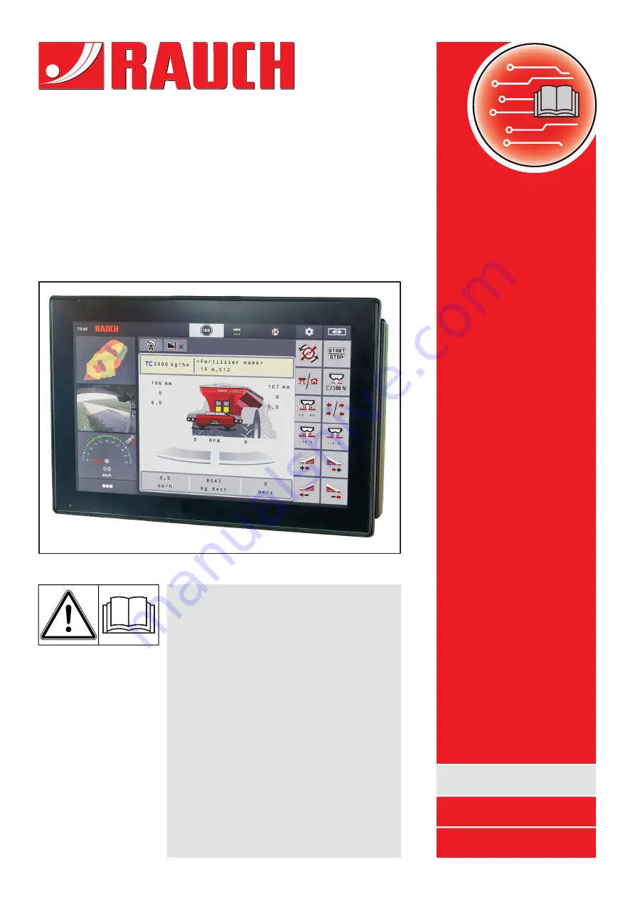
AXENT ISOBUS

Read carefully before

using the machine!

Keep for future reference.

This operator's manual/mounting manual
is to be considered as part of the
machine. Suppliers of new and second-
hand machines are required to document
in writing that the operator's manual/
mounting manual was delivered with the
machine and handed over to the
customer..

Version 5.02.00

5901646-

m

-en-0322

Original instructions

Complementary instructions

Summary of Contents for AXENT 100.1

Page 1: ...ual is to be considered as part of the machine Suppliers of new and second hand machines are required to document in writing that the operator s manual mounting manual was delivered with the machine a...

Page 2: ...s the operator s manual for the machine carefully before using the machine and follow the advice given This manual may also describe equipment that is not included in your machine control unit Technic...

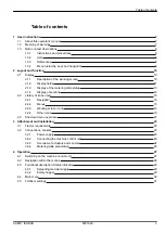
Page 3: ...ns used 15 2 2 1 Navigation 15 2 2 2 Menus 15 2 2 3 Working screen icons 16 2 2 4 Other icons 19 2 3 Structural menu overview 21 3 Attachment and installation 23 3 1 Tractor requirements 23 3 2 Connec...

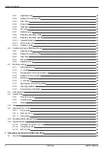
Page 4: ...de 56 4 7 2 quantity 57 4 7 3 Overloading function operating mode 58 4 7 4 Settings for lime operation 59 4 7 5 Belt speed 60 4 7 6 belt speed 60 4 7 7 Opening the pre metering slides 61 4 7 8 Opening...

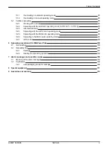
Page 5: ...2 5 Spreading with the MAN km h operating mode 94 5 2 6 Spreading in the MAN scale operating mode 94 5 2 7 GPS control 96 6 Spreading operation with LIME PowerPack 100 6 1 Overloading 100 6 2 Spreadin...

Page 6: ...Table of contents 6 5901646 AXENT ISOBUS...

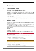
Page 7: ...re classified according to the severeness of the risk and the probability of its occurrence The warning symbols draw attention to the unavoidable residual risks inherent in the design to which users o...

Page 8: ...is a note General information containing application tips and particularly useful information but which constitutes neither warnings nor hazards 1 3 Notes on text descriptions 1 3 1 Instructions and p...

Page 9: ...n be made selection lists text or number entries starting a function The various menus and buttons of the machine control unit are illustrated in bold letters The hierarchy and the path to the request...

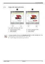
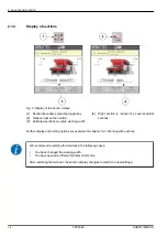
Page 10: ...l in the corresponding operator s manual 2 1 Display The display shows the current status information as well as the selection and input options for the electronic machine control unit The most import...

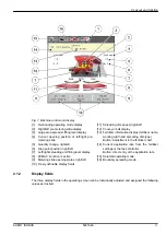
Page 11: ...ft 10 Freely definable display fields 11 Spreading disc speed right left 12 Conveyor belt display 13 Fertilizer information display fertilizer name working width and spreading disc type Button Adjustm...

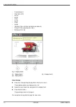
Page 12: ...ields 1 Display field 1 2 Display field 2 3 Display field 3 Select display u Press the corresponding display field in the touch screen The available options are displayed in a list u Select the new va...

Page 13: ...activated B Machine in spreading operation 3 Section deactivated 4 Section activated In boundary spreading mode you can immediately deactivate an entire spreading side This is particularly helpful for...

Page 14: ...duced by several partial sections Further display and setting options are explained in chapter 5 2 1 Working with sections We recommend restarting the terminal in the following cases You have changed...

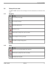
Page 15: ...e Go to the right next page Back to the previous menu Back to main menu Switch between working screen and menu window Acknowledgment of warning messages Cancellation closing the dialog window 2 2 2 Me...

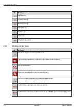
Page 16: ...ation rate The spreading operation has started stop the application rate regulation Start spreading discs Rotate the spreading discs stop the spreading discs Reset the quantity adjustment to the pre s...

Page 17: ...des Selection of the surplus shortage quantity on the left right or both spreading sides Quantity adjustment plus Quantity adjustment minus Quantity adjustment left plus Quantity adjustment left minus...

Page 18: ...tely deactivates an entire spreading side Increase left section plus Reduce section right minus In boundary spreading mode Pressing and holding 500 ms immediately deactivates an entire spreading side...

Page 19: ...u Full border spreading mode in the main menu Manual overloading is active Automatic overloading is active Operating mode AUTO km h AUTO kg Operating mode AUTO km h Operating mode MAN km h Operating m...

Page 20: ...peed Terminals with 2x6 function keys only Increase plus conveyor belt speed Terminals with 2x6 function keys only EMC control deactivated Loss of the GPS signal GPS J1939 The minimum mass flow is und...

Page 21: ...2 3 Structural menu overview 2 Layout and function AXENT ISOBUS 5901646 21...

Page 22: ...2 Layout and function 22 5901646 AXENT ISOBUS...

Page 23: ...pin ISOBUS socket at the rear of the tractor If the tractor is not equipped with a 9 pin socket at the rear a tractor assembly set including a 9 pin socket for the tractor ISO 11783 and a forward spe...

Page 24: ...Fig 5 Overview of actuators and sensors at the AXENT large area spreader 1 Hopper cover 2 Level sensor 3 Vibrator optional 4 Axis angle sensor Rear weigh cells left right Steering cylinder optional S...

Page 25: ...left right 7 Drop point actuator left 8 Dosing slider actuator left Left agitator 9 Interface connector for spreading units 10 Ultrasonic sensors 11 Pre metering slide hydraulic cylinder 12 Safety hoo...

Page 26: ...The machine has an electronic slide actuator to set the application rate Please observe the operator s manual for your machine 3 Attachment and installation 26 5901646 AXENT ISOBUS...

Page 27: ...control unit is displayed Subsequently the machine control unit displays the activation menu for a few seconds u Press the enter key The working screen then appears n Requesting the condition of the...

Page 28: ...erator s manual of the terminal used n Accessing the main menu u Press the Working screen main menu function key See 2 2 2 Menus The main menu is displayed Accessing the sub menu via the touch screen...

Page 29: ...tlet into the AXIS PowerPack or LIME PowerPack spreading unit Fig 7 Open pre metering slide display 1 Open pre metering slide 2 Standing conveyor belt 3 Running conveyor belt AXIS PowerPack The spread...

Page 30: ...eading material in the hopper is usually sufficient for a few overloading operations Despite the alarm message the AXENT ISOBUS machine control unit attempts full overloading of the residual quantity...

Page 31: ...ied out and functions for weighing operation 4 11 Weighing Trip counter In addition to the sub menus you can select function keys in the main menu See 2 2 4 Other icons 4 5 Fertilizer settings The mac...

Page 32: ...value for the application rate in kg ha 4 5 1 Application rate Working width m Determination of the working width to be spread 4 5 2 Setting the working width Flow factor Input of flow factor of the...

Page 33: ...d drop point Pre setting the drop point in the boundary spreading mode To be entered in a separate input window Limit bd rate Pre setting the application rate reduction in boundary spreading mode To b...

Page 34: ...e operator s manual for the special equipment 4 5 1 Application rate In this menu you can enter the target value for the desired application rate Entering the application rate u Access the menu Fertil...

Page 35: ...OK The new value is saved in the machine control unit 4 5 2 Setting the working width You can set the working width in meters in this menu u Access the menu Fertiliser settings Working width m The cu...

Page 36: ...lculated via the EMC mass flow control However the data may also be entered manually The flow factor calculation depends on the operating mode used For further information about the flow factor refer...

Page 37: ...s and possible causes CAUTION Risk of injury due to automatic adjustment of the drop point When the Start Stop function key is pressed the drop point is automatically moved to the preset value by an e...

Page 38: ...e is saved in the machine control unit The second calibration page is displayed Select the section u Set the spreader side on which the calibration is to be carried out Press the function key of the l...

Page 39: ...of 20 kg should be calibrated u Press Start Stop again The calibration is completed The metering slide closes The third calibration page is displayed n Calculating the new flow factor WARNING Risk of...

Page 40: ...he preset value by an electrical actuator Speedservo This may cause injury u Before pressing the Start Stop key ensure that nobody is present in the hazard zone of the machine u Acknowledge the Approa...

Page 41: ...f your machine The factory default speed is set to 750 rpm If you want to set a different speed you must change the saved value u Access the menu Fertiliser settings Normal disc speed u Enter the spee...

Page 42: ...cordance with the information provided in the fertilizer chart 4 5 9 Boundary spreading quantity In this menu you can reduce quantity value as a percentage This setting is used for the activation of t...

Page 43: ...r the required value in the menu Fertiliser settings Distance factor u Access the menu Fertiliser settings Calculate OptiPoint The first page of the Calculate OptiPoint menu is displayed The indicated...

Page 44: ...switches to the GPS Control info window 4 5 11 GPS Control info The GPS Control info menu informs you of the calculated setting values in the Calculate OptiPoint menu Depending on the terminal used t...

Page 45: ...application rate is overwritten by the stored value from the fertilizer chart You will be able to automatically manage fertilizer charts and to transfer them from your ISOBUS terminal Management of fe...

Page 46: ...sc type The display shows the selection window u Press the option Open and back to fertiliser settings The Fertiliser settings menu is displayed and the selected element is loaded into the fertilizer...

Page 47: ...op point and the normal disc speed The machine control unit will move the drop point to the value stored in the fertilizer chart Copying an existing fertilizer chart u Select the desired fertilizer ch...

Page 48: ...lizer chart is displayed Fig 17 Managing the fertilizer chart via the touch screen 1 Button Application rate 2 Button Fertiliser chart u Enter the new value in the input field u Press OK The new value...

Page 49: ...u Access the menu Main menu Fertiliser settings Not all parameters are displayed simultaneously on one screen You can switch to the next or previous menu windows tabs using the left right arrow keys F...

Page 50: ...ion with arrow keys confirmation with the Enter key Bound disc speed Pre setting the RPM in the boundary spreading mode To be entered in a separate input window Limit bd rate Pre setting the applicati...

Page 51: ...ne control unit 4 6 2 Setting the working width You can set the working width in meters in this menu u Access the menu Fertiliser settings Working width m The currently applied working width is displa...

Page 52: ...m Application rate max kg ha Burnt lime ground 1100 1 0 88 100 10 9700 Burnt lime granulated 1100 0 88 100 18 5380 Converter lime 1300 2 1 04 90 15 7640 Carbonated lime 1000 0 80 72 12 7340 Mixed lim...

Page 53: ...preading disc type 4 6 5 Rotation speed n Normal disc speed The factory default speed is set to 700 rpm If you want to set a different speed you must change the saved value u Access the menu Fertilise...

Page 54: ...in a separate input window MAN km h Setting the manual speed only influences the respective operating mode To be entered in a separate input window Speed signal source Selection limitation of the spe...

Page 55: ...screen If this function is deactivated the change can only be made as a percentage value No function in lime operation Fertilizer info Activation of the fertilizer information fertilizer name spreadi...

Page 56: ...rking with application maps Activation of two separate application rates for the right and left side respectively 4 7 1 AUTO MAN mode The machine control unit automatically adjusts the dosing quantity...

Page 57: ...on the screen We recommend having the flow factor displayed in the working screen By doing so you can observe the mass flow control during spreading See 2 1 2 Display fields Important information on t...

Page 58: ...al It is recommended to always work in automatic operating mode Automatic mode The machine control system fully automatically controls the valves for fertiliser supply according to sensor information...

Page 59: ...em Warning message no 39 is displayed See 7 1 Meaning of the alarm messages u Press ACK The warning message is acknowledged The box is checked The operating mode is active u Press the Start overloadin...

Page 60: ...IS PowerPack In this menu the speed of the conveyor belt can be defined During operation the speed of the conveyor belt can be adjusted in the operating screen See 4 7 6 belt speed u Access the menu M...

Page 61: ...adjustment n Only with AXIS PowerPack AXIS PowerPack In this menu a percentage adjustment of the pre metering slide opening can be defined The preset value of the pre metering slide opening serves as...

Page 62: ...can save up to 4 different profiles for the type and number of pulses and assign names to these pulses e g tractor name Before spreading check that the correct profile is opened in the control unit Fi...

Page 63: ...is known it can be entered directly u From the selected tractor profile select the Pulses 100m menu entry The Pulses menu is displayed for manual entry of the pulse count If the exact pulse count is u...

Page 64: ...u For this purpose before storing the machine we recommend completely opening the metering sliders with the fast emptying function and switching off the control unit in this state This prevents the ac...

Page 65: ...Before pressing the Start Stop key ensure that nobody is present in the hazard zone of the machine Fig 26 Menu Fast emptying 1 Icon for fast emptying here left side selected not started 2 Fast emptyin...

Page 66: ...amages u Before pressing the Start Stop key ensure that nobody is present in the hazard zone of the machine 4 9 System Test In this menu the system and test settings for the machine control unit can b...

Page 67: ...d spread quantity in kg spread area in ha spread time in h distance traveled in km This menu is for information purposes only Fig 28 Menu Total data counter 4 9 2 Test diagnosis In the Test diagnosis...

Page 68: ...he assemblies registered via LIN bus Example LIN bus Spreading disc Manual activation of the spreading disc Agitator Checking the agitator EMC sensors Checking the EMC sensors Weigh cell Checking the...

Page 69: ...r cover 1 Signal display 1 Safety hood is closed 0 Safety hood is open 2 Signal bar graph n Example Lime functions u Access the menu System Test Test diagnosis u Press the left right arrows to navigat...

Page 70: ...lider 1 Signal display 2 Signal bar graph 3 Position display The Signal display shows the status of the electrical signals for the left and right side separately CAUTION Risk of injury due to moving m...

Page 71: ...ons 0 OK no equipment error 2 blockage 4 overload CAUTION Risk of injury due to moving machine parts During the tests machine parts may move automatically u Before carrying out the tests ensure that n...

Page 72: ...ol unit This menu provides information on the configuration of the machine The information list depends on the equipment of the machine 4 11 Weighing Trip counter This menu provides values regarding s...

Page 73: ...is menu the values of the spreading work carried out can be obtained the remaining spreading quantity can be observed and the trip counter can be reset by deleting u Access the menu Weighing Trip coun...

Page 74: ...menu Weighing Trip count Rest kg ha m The Rest kg ha m menu appears The current fill weight in the weighing spreader can only be determined by weighing In all other spreaders the remaining fertilizer...

Page 75: ...s button The weighing value for the empty scales is now set to 0 kg Tare the scales before each use in order to ensure problem free calculation of the remaining quantity 4 12 Operating lights SpreadLi...

Page 76: ...item Activate 2 The operating lights are activated and remain on until you remove the check mark or leave the menu 4 13 Special functions 4 13 1 Changing the system of units Your system of units has b...

Page 77: ...536 kg ac left 1 x 0 4047 ha Working width ft 1 x 0 3048 m Appl rate lb ac 1 x 1 2208 kg ha Mounting height in 1 x 2 54 cm 4 13 2 Using the joystick As an alternative to the settings in the working sc...

Page 78: ...3 Plastic grid replaceable 4 Shift key n CCI A3 Joysticks operating levels You can switch between three operating levels with the shift key The level that is currently active is displayed by the posit...

Page 79: ...ck button functions The joystick offered is pre programmed with specific functions at the factory The meaning and function of the icons can be found in Chapter 2 2 Library of icons used Please note th...

Page 80: ...Fig 39 Button functions Level 1 Fig 40 Button functions Level 2 4 Operation 80 5901646 AXENT ISOBUS...

Page 81: ...ial equipment A WiFi module can be used for communication between a smartphone and the ECU The following functions are possible Transmission of information from the fertilizer charts app to the ECU Th...

Page 82: ...module You can find more information on assembly of the WiFi module and communication with the smartphone in the WiFi module assembly instructions The WiFi password is quantron 4 Operation 82 5901646...

Page 83: ...ive See 4 7 3 Overloading function operating mode Function control Operating screen display u Press Spreading disc start The conveyor belt starts up The pre metering slides open automatically The Powe...

Page 84: ...started and stopped by pressing the Start overloading key if a spreader side is empty The sensor conditions signal the required steps Requirement The manual operating mode is active See Manual AXIS Po...

Page 85: ...or belt is stopped Close the pre metering slides Overloading is completed 5 2 Fertilizer spreading 5 2 1 Working with sections n Displaying the spreading type in the operating screen The machine contr...

Page 86: ...s to adapt the full spreading width to the field requirements Every spreading side can be set continuously in the automatic mode and to a maximum of 4 steps in the manual mode u Press limited border s...

Page 87: ...splay changes to match the new settings u Press the Reduce left spreading width or the Reduce right spreading width function key The section of the spreading side will be reduced by one step u Press t...

Page 88: ...rol 1 Field edge 2 Headlands tramline 3 Sections 1 to 4 Section reduction on the right hand side Sections 5 to 7 further section reductions 4 Tramline in the field 5 Spreading operation with AXIS Powe...

Page 89: ...the limited border spreading side 7 Left section adjustable in 4 steps 8 The current boundary spreading mode is Limited bd The application rate on the left is set to the full working width The Right...

Page 90: ...e defined Application rate kg ha Working width m Spreading disc Normal disc speed RPM u Fill the hopper with fertilizer WARNING Risk of injury caused by ejected fertilizer Ejected fertilizer may cause...

Page 91: ...ssages 5 2 3 Idle measurement n Automatic idle measurement In order to achieve a high control accuracy the EMC control must regularly measure and store the idling pressure The idle measurement for the...

Page 92: ...completed the machine control unit will set the idling time to 19 59 minutes in the display of the working screen u Press Start Stop The spreading starts The idle measurement runs in the background ev...

Page 93: ...ing system Requirements for spreading The AUTO km h operating mode is active see 4 7 1 AUTO MAN mode The fertilizer settings are defined Application rate kg ha Working width m Spreading disc Normal di...

Page 94: ...ll the hopper with fertilizer In order to achieve an optimum spreading result in the MAN km h operating mode a calibration is to be carried out before starting the spreading u Carry out a calibration...

Page 95: ...ing material a constant forward speed must be applied in manual operating mode Fig 48 MAN scale operating screen 1 Display of metering slide target value scale position 2 Display of current metering s...

Page 96: ...machine control unit The A symbol next to the spreading wedges indicates that the automatic function is enabled The ISOBUS terminal with SectionControl opens and closes the individual sections depend...

Page 97: ...To ensure correct configuration of the OptiPoint function enter the correct aerodynamic factor for the fertilizer being used The aerodynamic factor can be obtained from the fertilizer chart for your...

Page 98: ...stance means that the switch on position is closer to the field border A greater value means that the switch on position is closer to the center of the field n Turn off distance m The Turn off dist m...

Page 99: ...that the switch off position is closer to the center of the field If you want to turn through the headland track enter a greater distance in Turn off dist m Here the adjustment must be as low as poss...

Page 100: ...is active u Start spreading u Press the start stop key at the end of work u Stop spreading discs The overload runs continuously depending on the spread quantity The belt speed and pre metering settin...

Page 101: ...kg ha u Press OK The new value is saved in the machine control unit Setting the working width u Access the menu Fertiliser settings Working width m u Enter the desired working width in the range betw...

Page 102: ...nction control Operating screen display u Press Spreading disc start The pre metering slides open automatically u Spreading operation start The conveyor belt starts up u Start spreading The speed of t...

Page 103: ...metering slides remain open u Press start stop again during travel into the field The conveyor belt is started u Press Start Stop at the end of the operation The conveyor belt is stopped Overloading i...

Page 104: ...Flow factor is outside limits The flow factor must lie within a range between 0 40 and 1 90 The newly calculated or entered flow factor is outside this range 4 Hopper left empty The filling level sen...

Page 105: ...aded For weighing spreader only The mineral fertilizer spreader is overloaded Too much fertilizer in the hopper 22 Unknown condition Function Stop Communication problem with terminal Possible software...

Page 106: ...the discs and close the metering sliders You may only switch to the System Test menu area if the spreading operation has been deactivated Stop spreading discs Close the metering slide 39 Manual mode...

Page 107: ...nal valve spring is jammed 72 Error at SpreadLight Power supply is too high the operating lights will be switched off 73 Error at SpreadLight Overload 74 Defect at SpreadLight Connection error Defecti...

Page 108: ...combined with certain machine types u Restart the machine control unit when changing machine type u Implement machine settings u Load fertilizer chart for the machine type 83 Reduce oil temp The oil...

Page 109: ...current is too high the LS valve is switched off 112 Fault on LS valve Overload 113 Fault on LS valve The LS valve has not be detected Cable breakage LS valve defective 7 2 Fault alarm An alarm messag...

Page 110: ...nowledging the alarm messages may differ You can use various keys to acknowledge other messages with a yellow frame Enter Start Stop For this purpose follow the instructions on screen 7 Alarm messages...

Page 111: ...8 Special equipment Illustration Designation Level sensor CCI A3 joystick WiFi module 8 Special equipment AXENT ISOBUS 5901646 111...

Page 112: ...pany representatives of the parent company if you have any questions or doubts Warranty claims must be submitted to the company within 30 days at the latest after the damage has occurred The date of p...

Page 113: ......

Page 114: ......
Reviews: