background image

Supplied By www.heating spares.co  Tel. 0161 620 6677

CONDENSING

FANNED FLUE BOILER

CSI SYSTEM

WITHOUT TIMER

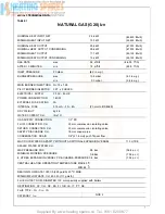
NATURAL GAS (G20) (I

2H

) G.C.N

o

 47 581 01 - CSI

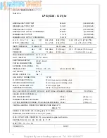
LPG (G30-G31) (I

3+

) G.C.N

o

 47 581 03 - CSI

Tested,  certified and

service listed

Listed by The United Kingdom Water

Fitting Byelaws Scheme

WITH TIMER

NATURAL GAS (G 20) (I

2H

) G.C. N

O

 47 581 02 - CSI

LPG (G 30 - G 31) (I

3+

) G.C.N

O

 47 581 04 - CSI

INSTALLATION AND SERVICING INSTRUCTIONS

TO BE LEFT WITH USER

Technical and illustrative data are not binding and can be modified without prior notice.
The descriptions and illustrations in the present booklet are for guideline purposes only.

RAVENHEAT MANUFACTURING LTD., CHARTISTS WAY, MORLEY, LEEDS, LS27 9ET. -TELEPHONE (0113) 252 7007

Summary of Contents for CSI System

Page 1: ...Water Fitting Byelaws Scheme WITH TIMER NATURAL GAS G 20 I2H G C NO 47 581 02 CSI LPG G 30 G 31 I3 G C N O 47 581 04 CSI INSTALLATION AND SERVICING INSTRUCTIONS TO BE LEFT WITH USER Technical and ill...

Page 2: ...exchanger for high thermal flue transfer gases to water Built in frost protection Printed circuit board designed to connect to room stat cylinder stat and or timer frost stat Aesthetically pleasing p...

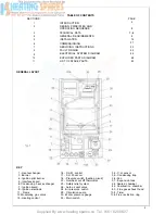
Page 3: ...ion pilot burner 5 Interface board 6 Condensing heat exchanger 7 Ignition board 9 Ignition electrode 11 Frame 12 Modulating gas valve 15 Heating control 16 D H W control 17 D H W sensor 18 Pressure sw...

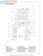
Page 4: ...Flue restriction ring 16 Hot water control potentiometer 6 Condensing heat exchanger 17 Water pressure switch 7 Electronic ignition 18 Overheat cut off thermostat 8 Condensing trap 20 Gas service coc...

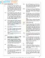
Page 5: ...At this point the ignition board opens the first step of the gas valve to light the pilot burner 2 2 4 2 2 5 2 2 6 Central heating mode 2 2 7 If the main neon switch is on with a demand for heat to su...

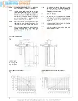
Page 6: ...operate 2 3 7 When the room thermostats and or timer in tervene the main burner shuts down The fan stops and the pump turns off via the pump overrun 2 3 6 The condensate trap is fitted with a block a...

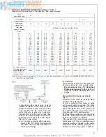
Page 7: ...PPLY CONNECTION 1 2 RC FLOW CONNECTION C H 22 mm compression isolating valve RETURN CONNECTION C H 22 mm compression isolating valve SAFETY DISCHARGE C H 15 mm copper pipe CONDENSATION DRAIN 3 4 21 5...

Page 8: ...HOLE ELECTRICAL SUPPLY 2 3 0 V 5 0 H Z POWER CONSUMPTION 160W EXTERNAL FUSE RATING 3A INTERNAL FUSE 315 mA 2A 4A 20 mm to BS 4265 DRY WEIGHT kg 46 WATER CONTENT C H litre 1 O GAS SUPPLY CONNECTION 1...

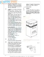
Page 9: ...g 60 kW DD 189 1990 Discharge of condensate Health Safety Document No 635 The Electricity at Work Regulations 1989 The manufacturer s notes must NOT be taken in any way as overriding statutory obligat...

Page 10: ...stal lation pipes should be fitted in accordance with BS 6891 Pipework from the meter to the boiler must be of adequate size 22 mm min To within at least 3 metre of the boiler 15 mm min can then be us...

Page 11: ...Where possible pipes should have a gradi ent to ensure air is carried naturally to air release points and water flows naturally to drain taps It should be ensured as far as possible that the applianc...

Page 12: ...ystems will present no problem 4 8 7 Mains water feed central heating There must be no direct connection to the mains water supply even through a non return valve without the approval of the Local Wat...

Page 13: ...factor across Note This pressure can be increased up to 1 5 bar to suit high static head situations see item 10 other appliance components in the SERVICING INSTRUCTIONS b A test clock c Double check...

Page 14: ...er Ravenheat recom mended only the use of FERNOX COPAL SENTINEL Xl00 or SALAMANDER CUR ROSION GUARD water treatment products which must be used in accordance with the manufacturers instructions For fu...

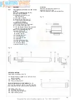
Page 15: ...copper tails complete with 3 4 brass nuts and washers Box 2 of 2 containing Fig 12 Horizontal CSI flue kit 57 Flue bend assembly 58 Header gasket 59 Rubber seal 0 60 60 Air intake duct 61 Flue exhaus...

Page 16: ...Supplied By www heating spares co Tel 0161 620 6677...

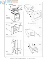
Page 17: ...op of the appliance to release them from their upper suspension hooks Fig 26 27 Make sure the casing and screws are put to one side in a safe place INSTALLINGTHE APPLIANCE FOR REAR FLUE OUTLET Use adh...

Page 18: ...er flue duct at right angles to a length equal to W 152 mm Must be de burred Cut the inner flue duct 60 mm at right angles to a length equal to W 264 mm Insert from cut end Reassemble the two tubes In...

Page 19: ...r secur i n g b o l t s 5 5 6 Working above the boiler pull the flue exhaust duct towards the boiler in order to engage tube 61 into its header 57A Position flue into elbow header and push so as to lo...

Page 20: ...cket is availa ble from Ravenheat Manufacturing and should be used to support flue length at least every 1 8 metre preferably at each joint this bracket should be secured to wall and flue duct 5 5 11...

Page 21: ...oiler on the wall Locate onto the top coach bolts Fit the lower coach bolts and tighten all four securing bolts Remove the centering spring 65 pull the flue terminal disengage inner flue duct 5 7 8 Wo...

Page 22: ...roof Fig 42 POSITION MIN DISTANCE mm N above roof level to base of terminal 300 P from adjacent wall to flue 300 Q from internal corner to flue 300 S from facing terminal 1 200 M horizontally from a...

Page 23: ...re the seal rings are correctly located Fig 44 Make sure that the entire flue is adequately supported Use at least one bracket for each extension used Ensure that all inner flue connections have a goo...

Page 24: ...Supplied By www heating spares co Tel 0161 620 6677 Fig 48A Fig 48B Schematic Y plan Schematic S plan Fig 49A POSlTlONlNG OF WATER AND GAS CONNECTIONS 24...

Page 25: ...rnal wiring must not be disturbed when wiring external controls 5 13 3 To gain access to external zone valve and cylinder stat connection box remove the 2 screws on the side of the plastic cover just...

Page 26: ...Supplied By www heating spares co Tel 0161 620 6677 2 6...

Page 27: ...ressure to the required value remove drain point Fig 93 or drain on the heating circuit LIGHTING THE BOILER Fig 50 Before lighting the main burner make sure that the heating circuit flow and return va...

Page 28: ...sect 5 4 3 Unscrew the two screws holding the control box cover and lift off Fig 78 Turn on main switch 1 Fig 50 Turn control thermostat 4 to maximum setting Fig 50 Check all external controls are on...

Page 29: ...gas exhaust hood 15 Connection pipe 18 Heat exchanger 24 Main burner 25 Pilot burner 27 Auto air vent valve 28 Pressure switch 29 Seal 31 Seal 37 Window seal 42 Window clamp ring 44 Fan 46 Header gask...

Page 30: ...age but in general once per year should be adequate WARNING Before the start of any servicing or replace ment of components always isolate electric 7 2 7 2 1 7 2 2 7 2 3 7 2 4 7 2 5 7 2 5 1 7 2 6 ity...

Page 31: ...cal connections from the fan motor Support the fan and remove the two fixing screws and bracket from the front of the flue hood Carefully withdraw from condensing heat exchanger then from the applianc...

Page 32: ...ow connections come out from the combustion chamber and then remove it Fig 64 7 8 13 Replace in reverse order Ensure correct wire position Fig 94 IMPORTANT When replacing a heat exchanger new seals mu...

Page 33: ...Supplied By www heating spares co Tel 0161 620 6677 7 10 TO REPLACE THE ELECTRODE Fig 66 7 10 1 Remove front casing sect 7 3 Remove combustion chamber front cover sect 7 4 Fig 56 Fig 60 Fig 62...

Page 34: ...and the combustion chamber front cover sect 7 3 7 41 Remove the lower sect 5 4 2 Fig 21 Release the fitting that secures pilot pipe at the gas valve Remove electrode sect 7 10 Unscrew pilot connection...

Page 35: ...7 3 4 Remove the pilot burner assembly as described in sect 7 13 Unscrew the union Fig 70 Unscrew the 4 screws securing the injector manifold to the burner Fig 71 Pull the manifold up and out from th...

Page 36: ...HE GAS VALVE Fig 51 Remove front casing panel sect 7 3 Push the 2 clips that fasten the instrument panel Fig 23 Lift the instrument panel to detach it from the sides and lower it down by rotating it o...

Page 37: ...heat thermostat making sure that these wires will subsequently be reconnect ed to the same poles Fig 94 7 25 1 7 25 2 7 22 5 Remove the split pin and pull the thermo stat sensor from its pocket 7 22 7...

Page 38: ...d cover ensuring that con nection wire br L and bl N 7 25 10 Refill the heating system as described in the sect 6 4 5 and check for leaks 7 27 TO REMOVE REPLACE THE CENTRAL HEATING AND OR HOT WATER CO...

Page 39: ...wer coach bolts and release 2 top coach bolts then remove boil er from the wall 7 28 10 Unscrew the nut that connects the expan sion vessel and remove it Fig 91 7 28 11 Remove the screw supporting exp...

Page 40: ...rom p a n e l 7 31 4 Remove two clips securing the timer 7 31 5 Carefully remove the four wires connecting timer by pulling spade connectors from timer 7 31 6 Replace in reverse order ensure all elect...

Page 41: ...Supplied By www heating spares co Tel 0161 620 6677 Fig 90 Fig 91 Fig 93 41...

Page 42: ...Supplied By www heating spares co Tel 0161 620 6677 SECTION 8 FAULT FINDING CENTRAL HEATING Switch on Stat to maximum Ensure external controls calling for heat Room Stat Time Clock TRV DHW Stat 42...

Page 43: ...pplied By www heating spares co Tel 0161 620 6677 BOILER NOT OPERATIONAL ON TIMER INTEGRAL Switchon Select Winter CentralHeating Stat to Maximum Ensure External control calling for heat Room Stat TRV...

Page 44: ...Supplied By www heating spares co Tel 0161 620 6677 SECTION 9 ELECTRICAL SYSTEM DIAGRAM Fig 94 44...

Page 45: ...Supplied By www heating spares co Tel 0161 620 6677...

Page 46: ...e illustrated by drawings IMPORTANT Correct F1 orifice must be fitted Supplied with the CSI twin flue header is a F1 orifice plate along with supplementary depression seal Before fixing the twin flue...

Page 47: ...ed NOTE for eccentric vertical flue a 125 mm 5 in diameter flashing plate will be required 90o M F bend consisting of 90o elbow with 0 ring side F 80 mm dia 0 ring 135 M F bend consisting of 135 elbow...

Page 48: ...OTE The pressure loss for each elbow fitted is 90o slow bend less 3 metre of pipe for each one fitted 45o bend less 1 5 metre of pipe for each one fitted IMPORTANT inlet and exhaust terminals must nev...

Page 49: ...Supplied By www heating spares co Tel 0161 620 6677...
Page 50: ...rt No Part No E23 711 E23 712 E23 729 371267 E23 732 E23 730 372842 E23 715 371268 E23 716 E23 733 372845 E23 718 E24 630 372849 173100 372 866 372894 E23 731 E23 735 372888 372851 372867 173101 E23 7...

Page 51: ...0 5009080 372896 Circulation pump 81 0013GUA01045 0 371274 Gasket 48 x 42 x 1 82 5003283 372874 Brass manifold 83 5015010 372897 Safety relief valve 3 bar 85 0012FUS05020 0 E23 724 Internal fuse 4A 87...

Page 52: ...Supplied By www heating spares co Tel 0161 620 6677 Chartists Way Morley Leeds LS27 9ET Telephone 0113 252 7007 Tfax 0113 238 0229...

Reviews: