background image

1

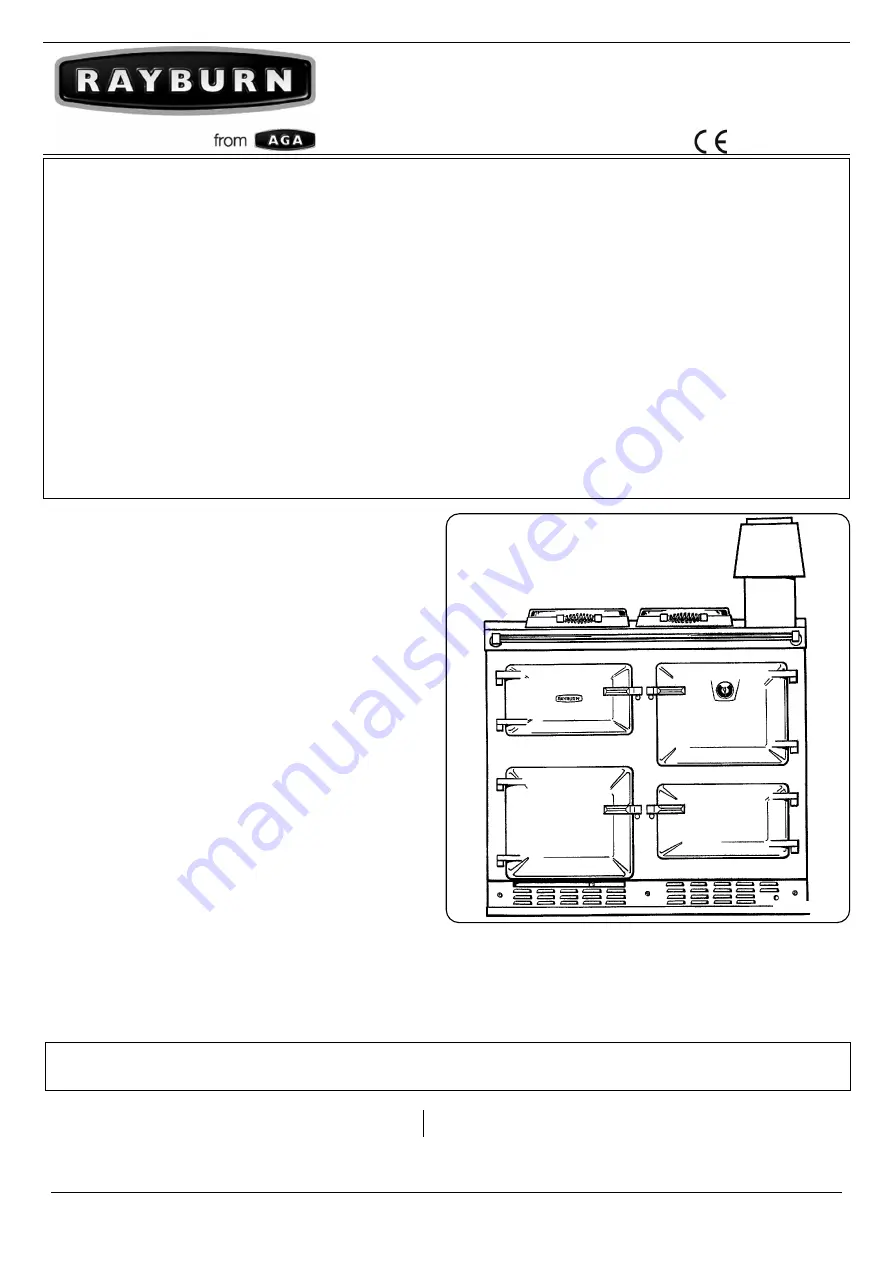
Heatranger 480AG (CF)/480AL (CF)

Installation and Servicing Instructions

raywarranty@aga-web.co.uk

09/22 EINS 512112

LPRT 512180

Consumer Protection

As responsible manufacturers we take care to make sure 

that our products are designed and constructed to meet the 

required safety standards when properly installed and used.

IMPORTANT NOTICE: PLEASE READ THE ACCOMPANYING 

WARRANTY.

 Any alteration that is not approved by AGA, 

could invalidate the approval of the appliance, the warranty 

and could also infringe the current issue of the statutory 

requirements.

All local regulations including those referring to national 

and European standards need to be complied with when 

installing this appliance.

Control of Substances - Health & Safety Important

This appliance may contain of the materials that are 

indicated below. It is the Users/Installers responsibility to 

ensure that the necessary personal protective clothing 

is worn when handling, where applicable, the pertinent 

parts that contain any of the listed materials that could be 

interpreted as being injurious to health and safety, see below 

for information.

Firebricks, Fuel beds, Artificial Fuels

- when handling use 

disposable gloves.

Fire Cement

 - when handling use disposable gloves.

Glues and Sealants

 - exercise caution - if these are still in 

liquid form use face mask and disposable gloves.

Glass Yarn, Mineral Wool, Insulation Pads, Ceramic Fibre, 

Kerosene Oil

 - may be harmful if inhaled, may be irritating 

to skin, eyes, nose and throat. When handling avoid inhaling 

and contact with skin or eyes. Use disposable gloves, 

face-masks and eye protection. After handling wash hands 

and other exposed parts. When disposing of the product, 

reduce dust with water spray, ensure that parts are securely 

wrapped.

Introduction

THIS APPLIANCE MUST BE INSTALLED IN ACCORDANCE 

WITH THE RULES IN FORCE AND USED ONLY IN A 

SUFFICIENT VENTILATION SPACE.
USE ONLY ON FULLY PUMPED SYSTEMS

This Rayburn Gas combination appliance is combined 

cooker and hot water boiler providing central heating and 

domestic hot water in addition to special cooking facilities. It 

is available in open flue form, operating on natural draught, 

the boiler being designed for use in fully pumped, open or 

sealed systems. Two separate independent controlled gas 

burners provide heat. One burner for central heating boiler 

section, providing heating and hot water, whilst the other 

burner provides heat to the cooker.

REMEMBER, when replacing a part on this appliance, 

use only spare parts that we require. Do not use 

reconditioned or copy parts that have not been clearly 

authorised by AGA.

Regulations

In the interests of safety all gas appliances should be 

installed by competent persons, in accordance with the 

regulations in force.

FOR USE IN GB & IE 

DESN 512129

PLEASE READ THESE INSTRUCTIONS BEFORE INSTALLING THE APPLIANCE

Summary of Contents for Heatranger 480AG CF

Page 1: ...e mask and disposable gloves Glass Yarn Mineral Wool Insulation Pads Ceramic Fibre Kerosene Oil may be harmful if inhaled may be irritating to skin eyes nose and throat When handling avoid inhaling an...

Page 2: ...13 Main burner lighting 14 Spillage test 14 Servicing 15 Annual servicing 15 Service schedule 15 Pre service check 15 Hotplate cleaning 15 Burner access 15 Burner cleaning 16 Heat exchanger 18 Combust...

Page 3: ...rner pressure Min Boiler Output 17 6kW at 8mbar burner pressure 480AL PROPANE G31 TOTAL BOILER COOKER MIN MAX MIN MAX Max Heat Inputs Gross 35 8kW 40 7kW 25 6kW 30 5kW 10 2kW Max Heat Inputs Net 33 0k...

Page 4: ...ke and flame Where the cooker is to stand in a recess or against a wall which is to be tiled in no circumstances should the tiles overlap the cooker top plate NOTE SMOKE SMELL EMITTED DURING INITIAL U...

Page 5: ...LER MUST MAKE PROVISION TO GAIN ACCESS TO 22mm COPPER FLOW AND RETURN PIPE DURING INSTALLATION R 1 2 1 2 BSP TAPER 10mm 10mm 50mm MINIMUM GAP ON RIGHT HAND SIDE MINIMUM GAP ON LEFT HAND SIDE WALL PROJ...

Page 6: ...ipe constructed in a to c above should form the initial connection to lined chimneys Where a chimney is to be used which is not composed of or lined with a non porous acid resistant material it should...

Page 7: ...e pipes should rise upwards in the direction away from the appliance Circulating Pump It is recommended that the selected pump be sized to suit the boiler pressure loss see Fig 1 3 and therefore adequ...

Page 8: ...lowing items which are supplied separately packed and require assembly 1 Draught Diverter Assembly See Fig 1 4 2 Appliance Rear Distance Bracket for use when appliance is installed 25mm away from a re...

Page 9: ...take the weight of the appliance on the crowbar and remove the rear rolled tube followed by similar action on the front tube 2 Assemble and locate the flue draught diverter assembly on flue spigot as...

Page 10: ...ed so that it is operated on demand only Operation of the system under control of the boiler thermostat only does not produce the best efficiency Refer to the control equipment manufacturer s literatu...

Page 11: ...ive MUST be connected to the terminal marked BSL NOTE The link between terminals L1 and BSL MUST be removed to ensure correct operation of the time switch If the time switch is fitted to the cooker th...

Page 12: ...INK L1 TO CSL OR PROVIDE TIMED LIVE FOR COOKER BURNER LINK L1 TO BSL OR PROVIDE LIVE SUPPLY TO BOILER FROM PROGRAMMER OR AUXILIARY CONTROLS G Y G Y G Y G Y WH BL Y 9 8 7 3 G Y BR BR BL BR BR OR OR BL...

Page 13: ...ighting the pilot Boiler see Fig 1 14 This appliance is fitted with an automatic ignition unit that will light the main burner on demand Should button K see Fig 1 14 be illuminated press button this w...

Page 14: ...k the system for leaks When all the air has been removed from the water circuit the pump and radiators should be balanced to achieve the correct temperature to drop across the system Set any timer roo...

Page 15: ...rs 5 Clean the heat exchanger 6 Check the condition of the boiler combustion chamber insulation 7 Check that the flueway is unobstructed and that the draught diverter unit is correctly assembled 8 Ove...

Page 16: ...Fig 1 18 Brush the boiler burner top and check the flame ports are clear Any deposits may be removed with a non metallic brush Remove three screws securing burner assembly to manifold A Remove two sc...

Page 17: ...ing injector bracket and remove controls away from burner door Brush burner venturi and remove any deposits from inside the burner venturi and tip downwards to discharge debris Remove the burner injec...

Page 18: ...access plate See Fig 1 24 Remove access plate R Using a suitable brush clean the heat exchanger from above and below NOTE The insulation used on the inside surface of the combustion chamber is delica...

Page 19: ...ON Following the sequence in COMMISSIONING INSTRUCTIONS To fit new burner Follow instructions in section Burner Cleaning of Servicing Instructions and remove the cooker burner assembly 1 Remove two p...

Page 20: ...rmostat control knobs 3 Remove the 2 cover panel fixing screws 4 Remove cover panel SEE Fig 1 26 5 Remove the two control panel fixing screws 6 Tilt the chassis from the top and lift out taking care n...

Page 21: ...thermostat capillaries 9 Re assemble in reverse order To fit new cooker overheat See Fig 1 27 AND Fig 1 28 Follow instructions in ELECTRICAL COMPONENT ACCESS Steps 1 to 6 1 Undo the two screws on the...

Page 22: ...or 3 Fit replacement 4 Re assemble in reverse order 5 Check for gas soundness To fit new burner Follow instructions in section Burner cleaning Instructions and remove the boiler burner assembly 1 Remo...

Page 23: ...spindle locknut and extract overheat thermostat 5 Fit replacement thermostat 6 Re assemble in reverse order To fit combustion discharge safety device SEE Fig 1 33 Fig 1 34 1 Remove CDSD phial from sp...

Page 24: ...er or return side of all heat emitters or radiators b Where access to a make up vessel would be difficult by a remote automatic pressurisation and make up unit c Mains Connection There shall be no con...

Page 25: ...LTERNATIVELY THE BYPASS LOOP CAN INCORPORATE A TOWEL RAIL CONTROLLED BY A NON ADJUSTABLE BALANCING VALVE SHOULD THE PUMP BE FITTED TO THE RETURN THEN THE PRESSURE GAUGE AND EXPANSION VESSEL ARE FITTED...

Page 26: ...change specifications and make modifications to the appliances described and illustrated at any time www agaliving com www agacookshop co uk Manufactured By AGA Rangemaster Station Road Ketley Telfor...

Reviews: