background image

New a Series
New c Series
New e Series 

Installation and operation
instructions

English

Date: 02-2013
Document number: 81337-6-EN
© 2013 Raymarine UK Limited

New a Series / New c Series / New e Series

Summary of Contents for a67

Page 1: ...New a Series New c Series New e Series Installation and operation instructions English Date 02 2013 Document number 81337 6 EN 2013 Raymarine UK Limited...

Page 2: ......

Page 3: ...s patents pending or design patents pending Fair Use Statement You may print no more than three copies of this manual for your own use You may not make any further copies or distribute or use the manu...

Page 4: ......

Page 5: ...k connections 43 4 6 GPS connection 50 4 7 AIS connection 50 4 8 Fastheading connection 51 4 9 SeaTalkng connections 51 4 10 SeaTalk connection 53 4 11 New a Series DSC VHF radio connection 53 4 12 NM...

Page 6: ...2 Radar scan speed 161 16 3 Radar scanner status symbols 161 16 4 Radar range and image quality 162 16 5 Radar display overview 164 16 6 Dual range radar operation 165 16 7 Radar mode and orientation...

Page 7: ...63 25 1 Raymarine mobile apps 264 25 2 Enabling Wi Fi 265 25 3 Enabling mobile apps 265 25 4 Setting up Wi Fi security 266 25 5 Selecting a Wi Fi channel 266 Chapter 26 Customizing your display 267 26...

Page 8: ...8 New a Series New c Series New e Series...

Page 9: ...en display can get very hot In such conditions avoid using the touchscreen display or use the unit s physical keys and buttons instead if available Warning Touchscreen display Exposure to prolonged ra...

Page 10: ...interference between equipment and minimize the effect such interference could have on the performance of your system Correct installation is required to ensure that EMC performance is not compromised...

Page 11: ...elevant product page at www raymarine com Product disposal Dispose of this product in accordance with the WEEE Directive The Waste Electrical and Electronic Equipment WEEE Directive requires the recyc...

Page 12: ...12 New a Series New c Series New e Series...

Page 13: ...Chapter contents 2 1 Handbook information on page 14 2 2 Product information on page 15 2 3 Handbook illustrations on page 16 2 4 Handbook conventions on page 17 2 5 Touch and non touch operations on...

Page 14: ...ew e Series Handbooks Description Part number e7 e7D Mounting and getting started guide 88011 New c Series New e Series Mounting and getting started guide 88001 New a Series New c Series New e Series...

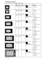
Page 15: ...h Wi Fi NMEA 0183 NMEA 2000 via SeaTalkng Internal GPS Video input e95 E70021 e97 E70022 New e Series HybridTouch Touchscreen and physical buttons Bluetooth Wi Fi NMEA 0183 NMEA 2000 via SeaTalkng Int...

Page 16: ...slightly from your display model The illustration of the multifunction display below is used throughout this manual and unless otherwise stated can apply to all variants of multifunction display i e...

Page 17: ...cations to refer to the action of selecting a location object or target on screen using touch or physical buttons Touch Press and hold your finger on a location to select or Touch Press and release yo...

Page 18: ...ill be either a Waypoint MOB button or an on screen icon WPT button New c Series New e Series WPT icons New a Series Throughout this manual the term Select WPT refers to pressing the physical WPT butt...

Page 19: ...nd New e Series displays This handbook uses icons throughout to identify whether a particular task is a touch or a non touch operation Touch Touchscreen operation Touch operations apply to New a Serie...

Page 20: ...20 New a Series New c Series New e Series...

Page 21: ...27 3 5 Identifying your display variant on page 27 3 6 Networking constraints on page 28 3 7 Typical systems on page 29 3 8 System protocols on page 32 3 9 Data master on page 33 3 10 New a Series pa...

Page 22: ...function display For Raymarine wireless video streaming and remote control apps Apple iPhone 4 or later or iPad 2 or later Android device with minimum 1GHz processor and running android 2 2 2 or later...

Page 23: ...heads Raymarine As determined by SeaTalk or SeaTalkng bus bandwidth and power loading as appropriate SeaTalk via optional SeaTalk to SeaTalkng converter ST6002 ST7002 ST8002 SeaTalkng ST70 SeaTalkng c...

Page 24: ...rs Airmar 1 DT800 Smart Sensor DST800 Smart Sensor PB200 weather station SeaTalkng via optional transducer pods 14 Video out New e Series excluding e7 and e7D 1 External display 15 pin D Type connecto...

Page 25: ...50C DSM30 DSM300 SeaTalkhs 20 Radar Raymarine 1 All Raymarine Non HD Digital Radomes and HD or SuperHD radar scanners Note Please ensure your radar scanner is using the latest software version SeaTalk...

Page 26: ...connections into equipment 7 Secure all equipment in place 8 Power on and test the system 3 3 System Limits The following limits apply to the number of system components that can be connected in a Ray...

Page 27: ...be available all products in the system that use the data sources listed above must be MDS compliant The system can list any products that are NOT compliant It may be necessary to upgrade the softwar...

Page 28: ...oftware version V4 xx or later will permit the connection of up to 2 New a Series New c Series or New e Series displays or 2 E Series Widescreen displays or 1 of each e g 1 New e Series and 1 E Series...

Page 29: ...Multifunction display 2 Raymarine network switch 3 Raymarine radar scanner 4 SPX course computer 5 SeaTalkng Pilot controller Note A network switch is only required if multiple devices are connected u...

Page 30: ...transducer 3 Radar scanner 4 SPX course computer 5 SeaTalkng pilot controller Example Basic system with non sonar variant display SeaT alkng SeaT alkhs RayNet SMARTPILOT D12590 1 1 2 3 4 5 1 Multifunc...

Page 31: ...2 12 14 9 15 2 3 4 6 13 10 7 1 Radar scanner 2 Weather sensor 3 Sirius weather receiver 4 Sonar module 5 SeaTalkng Pilot controller 6 SeaTalkng Instrument display 7 AIS receiver transceiver 8 Audio sy...

Page 32: ...hole network of marine electronics from any manufacturer to communicate on a common bus via standardized message types and formats SeaTalk SeaTalk is a protocol which enables compatible instruments to...

Page 33: ...ible repeat displays Information shared by the data master includes Cartography Routes and waypoints Radar Sonar Data received from the autopilot instruments the engine and other external sources Your...

Page 34: ...ingual CD Mounting and getting started multilingual guide Mounting template Warranty policy 8 Power and data cable 9 Trunnion bracket kit 3 12 New c Series and New e Series parts supplied The parts sh...

Page 35: ...saw 3 Pozidrive screwdriver 4 Adhesive tape 5 Spanner for surface mounting or bracket mounting fixings 6 File 7 Hole saw for flush mounting For hole saw size refer to your product s mounting template...

Page 36: ...36 New a Series New c Series New e Series...

Page 37: ...ge 50 4 8 Fastheading connection on page 51 4 9 SeaTalkng connections on page 51 4 10 SeaTalk connection on page 53 4 11 New a Series DSC VHF radio connection on page 53 4 12 NMEA 0183 connection on p...

Page 38: ...deckhead use a suitable watertight feed through Do NOT run cables near to engines or fluorescent lights Always route data cables as far away as possible from other equipment and cables high current ca...

Page 39: ...ow D12249 5 e7 e7D e95 e125 e165 e97 e127 c95 c125 c97 c127 a65 a67 0 0 0 0 0 0 0 0 0 0 Power Data Transducer SeaTalkng SeaTalkhs RayNet Network 1 SeaTalkhs RayNet Network 2 Video in out Power Video N...

Page 40: ...d be either Negative grounded with the negative battery terminal connected to the vessel s ground Floating with neither battery terminal connected to the vessel s ground Warning Positive ground system...

Page 41: ...inal connected to the vessel s ground Floating with neither battery terminal connected to the vessel s ground Warning Positive ground systems Do not connect this unit to a system which has positive gr...

Page 42: ...necting an in line fuse for each power circuit D11637 2 2 4 4 1 3 1 Positive bar 2 Negative bar 3 Circuit breaker 4 Fuse Where possible connect individual items of equipment to individual circuit brea...

Page 43: ...ner 4 Thermal camera Note New a Series displays do not support connection to a thermal camera Network hardware Item Part number Notes HS5 SeaTalkhs network switch A80007 5 port switch for network conn...

Page 44: ...ayNet male to RayNet male cable A80162 400 mm 1 3 ft RayNet to SeaTalkhs female adaptor A80160 RayNet cable puller 5 pack R70014 SeaTalkhs network cables Cable Part number 1 5 m 4 9 ft SeaTalkhs netwo...

Page 45: ...For longer cable runs a radar power and data digital cable extension is required D12254 1 1 4 2 3 1 Radar extension cable 2 Radar power and data digital cable 3 Raymarine network switch or crossover...

Page 46: ...r variant multifunction displays feature a built in sonar enabling you to connect the display directly to a compatible sonar transducer Non sonar variants require a connection to an external Raymarine...

Page 47: ...ar module and can be connected directly to compatible sonar transducers Sonar variants Non sonar variants a67 a65 e7D e7 c97 c95 c127 c125 e97 e95 e127 e125 e165 Minn Kota transducer adaptor cable Con...

Page 48: ...or connecting the PoE injector to the network switch Network patch cables are available in a variety of lengths Video cables Video cables are not supplied with the product Please contact your dealer f...

Page 49: ...n display 5 Networked multifunction displays Note The Fusion entertainment system can be controlled by a directly connected multifunction display or by a networked multifunction display Network connec...

Page 50: ...ion display 2 SeaTalkng GPS receiver GPS connection NMEA 0183 D12262 1 NM EA0183 1 2 1 Multifunction display 2 NMEA 0183 GPS receiver 4 7 AIS connection A compatible AIS can be connected using SeaTalk...

Page 51: ...rse computer SeaTalk equipment via the optional SeaTalk to SeaTalkng converter NMEA 2000 equipment via optional DeviceNet adaptor cables Typical SeaTalkng system S SM MA A R RT T P PI IL L O OT T D121...

Page 52: ...6039 SeaTalkng 3 m 9 8 ft spur A06040 SeaTalkng 5 m 16 4 ft spur A06041 SeaTalkng 0 4 m 1 3 ft elbow spur A06042 SeaTalkng 0 4 m 1 3 ft backbone A06033 SeaTalkng 1 m 3 3 ft backbone A06034 Description...

Page 53: ...k extension cable D285 5 m 16 4 ft SeaTalk extension cable D286 9 m 29 5 ft SeaTalk extension cable D287 12 m 39 4 ft SeaTalk extension cable E25051 20 m 65 6 ft SeaTalk extension cable D288 4 11 New...

Page 54: ...vice connected to the display s Port 1 OUTPUT both NMEA devices must be using the same baud rate You can connect up to 4 NMEA 0183 devices to the display s NMEA 0183 OUTPUT Port 1 You can connect a to...

Page 55: ...aTalkng to DeviceNet adaptor cable 3 DeviceNet backbone 4 NMEA 2000 equipment 4 14 Camera Video connection A camera or a video device can be connected directly to New c Series and New e Series multifu...

Page 56: ...hermal camera Note To listen to a movie s audio track any connected DVD or digital video player will require speakers to be connected to the players audio output Video out Examples of video output dev...

Page 57: ...in the list A pairing request message is displayed on the external media device 9 On the external media device select Pair or equivalent to accept the pairing request message The multifunction display...

Page 58: ...ccessed using a combination of the 3 buttons For some functions you must press a button MOMENTARILY You can also HOLD a button for continuous response for example continuous ranging in the chart appli...

Page 59: ...ccess message will be displayed If a Pairing Failure or Pairing Timeout message is displayed repeat steps 1 to 8 Customizing the SHORTCUT button On your multifunction display with the homescreen displ...

Page 60: ...ary response Hold UP or DOWN arrow for continuous response Toggle menu items and options in dialogs and prompts in left to right top to bottom order Press UP or DOWN arrow for momentary response Hold...

Page 61: ...es 10 M inutes 10 15 20 25 30 M inutes 35 40 45 50 55 60 5 3 To restore the connection between the 2 units press and hold any button on the RCU 3 for at least 3 seconds 3 Seconds 10 15 20 25 30 Second...

Page 62: ...able the relevant Mobile app in the System Settings menu on the multifunction display Note The multifunction display acts as a Wi Fi access point If your device already connects to an access point for...

Page 63: ...Chapter 5 Location and mounting Chapter contents 5 1 Selecting a location on page 64 5 2 Mounting New a Series on page 65 5 3 Mounting New c Series and New e series on page 67 Location and mounting 63...

Page 64: ...ible to the vessel s DC power source This will help to keep cable runs to a minimum Compass safe distance To prevent potential interference with the vessel s magnetic compasses ensure an adequate dist...

Page 65: ...issues related to the prevailing conditions Viewing angle considerations As display contrast color and night mode performance are all affected by the viewing angle Raymarine recommends you temporarily...

Page 66: ...all installations It may also be necessary to use a marine grade sealant if the mounting surface or binnacle is not entirely flat and stiff or has a rough surface finish Bracket trunnion mounting The...

Page 67: ...irm motion apply pressure to the outer edge of the display with your thumbs and pull the bezel towards you using your fingers The bezel should now come away from the display easily 5 3 Mounting New c...

Page 68: ...nto the display unit and press firmly onto the flange 8 Connect the power data and other cables to the unit 9 Slide the unit into place and secure using the fixings provided Note The supplied gasket p...

Page 69: ...he bezel latch into position D12274 1 4 Ensure the bezel is correctly aligned with the display as shown 5 Apply firm but even pressure to the bezel along the i Outer edges work from the sides upwards...

Page 70: ...70 New a Series New c Series New e Series...

Page 71: ...8 Homescreen overview New c Series New e Series on page 76 6 9 System checks on page 77 6 10 Enabling autopilot functions on page 80 6 11 Enabling AIS functions on page 80 6 12 Pages on page 81 6 13 A...

Page 72: ...onnected radars are switched on Enabling PowerSave mode To enable PowerSave mode follow the steps below 1 Ensure any radars connected to the system are switched off 2 Press the POWER button The shortc...

Page 73: ...rate many common functions including all menu operations HybridTouch multifunction displays only 2 Home Press to return to the homescreen 3 Menu accesses menus Press again to close menus 4 UniControl...

Page 74: ...D7366_3 The cursor appears on the screen as a white cross D7368_2 If the cursor has not been moved for a short period of time it changes to a circle with a cross in it to make it easier to locate on...

Page 75: ...y recommends that you activate the touch lock and use the physical keys to operate your multifunction display 6 6 Touchscreen overview The touchscreen provides an alternative to using physical buttons...

Page 76: ...s to your data waypoints routes and tracks The homescreen consists of a number of application pages each represented by an icon Applications can be started by selecting the relevant page icon Use the...

Page 77: ...ew to show the position of tracked satellites D12204 1 6 1 4 2 3 5 Item Description 1 Sky view a visual representation of the position of tracked satellites 2 Satellite status displays the signal stre...

Page 78: ...face when the sonar is powered on SWITCH OFF the sonar if divers are likely to be within 7 6 m 25 ft of the transducer Sonar transducer and sonar module selection You must designate the sonar transdu...

Page 79: ...e The relevant numeric adjust control is displayed 4 Adjust the value as required 5 Select Back or Ok to confirm the new value Panning and tilting and the thermal image On a New e Series multifunction...

Page 80: ...steps 1 to 5 above 6 The Pilot Control dialog is displayed indicating that pilot control is enabled and an autopilot is detected 6 11 Enabling AIS functions Before proceeding ensure your AIS unit is...

Page 81: ...it over to the displayed page 7 Select Finish The Rename Page dialog is displayed 8 Use the on screen keyboard to name the page then select Save Changing an empty page With the homescreen displayed 1...

Page 82: ...n your multifunction display Doc Viewer view pdf documents stored on a MicroSD card FUSION Link application link to and control a compatible Fusion entertainment system from your multifunction display...

Page 83: ...essel and its environment The position and type of information in the databar can be customized from the Homescreen Customize Databar Set up menu if required 3 Menu The menu options are specific to th...

Page 84: ...cts the item To scroll a menu touch a menu item and hold your finger down on the item while dragging your finger up or down Non touchscreen Use the Rotary control to highlight an item and the Ok butto...

Page 85: ...this icon to close the menu s The close icon is not available on non touchscreen displays Using control dialogs Control dialogs enable you to control externally connected equipment such as an autopilo...

Page 86: ...edit numerical values in you can either use the Rotary Control the on screen numeric adjust control or on screen numeric keypad to increase or decrease the value D12567 1 1 2 3 4 1 Select the numeric...

Page 87: ...ctions to your system have been made The symbols show the status for the following Radar scanner AIS receiver transceiver Sonar module GPS receiver Autopilot Radar scanner status symbols The radar sca...

Page 88: ...connected or is not detected GPS status symbols The GPS receiver status is indicated in the databar Symbol Description A GPS receiver is connected and has obtained a fix A GPS receiver is not connect...

Page 89: ...s to the required level using the on screen brightness slider bar control or 3 Touch the Sun icon to increase the brightness level or the Moon icon to decrease the brightness level Note The brightness...

Page 90: ...or external GPS receiver Your multifunction display may feature an internal GPS receiver You can also connect an external GPS receiver using SeaTalkng or NMEA 0183 Where appropriate use the System Se...

Page 91: ...overview on page 92 7 2 Inserting a memory card or chart card on page 92 7 3 Removing a memory card or chart card on page 93 7 4 Saving user data and user settings on page 93 7 5 Screenshots on page...

Page 92: ...a Series displays have 1 card slot cards must be inserted into New a Series displays with the contacts facing up 1 Open the chart card door located on the front right of the display 2 Insert the card...

Page 93: ...tings to a memory card on a regular basis Note Raymarine strongly recommends that you save settings to a separate memory card and NOT to a chart card containing cartography Saving waypoints routes and...

Page 94: ...ttings from a memory card With the homescreen displayed 1 Ensure you have the memory card containing the user data in one of the card slots 2 Select My Data 3 Select Backup and Restore Settings 4 Sele...

Page 95: ...hotos Roads Additional wrecks Aerial photo overlay colored seabed areas Vessel icon Vessel size Radar application Application Setting Select scanner Radar Range rings AIS Layer Application Setting Dis...

Page 96: ...Images The file browser dialog is displayed 4 Browse to the location on the SD card to where the image is saved 5 Select the image you want to view The image will now open 6 Select Back or Close to c...

Page 97: ...Chapter 8 Document viewer application Chapter contents 8 1 Document viewer overview on page 98 Document viewer application 97...

Page 98: ...iewer 2 Select User Manual The product user manual is opened Opening a pdf document You can open pdf documents stored on an SD card by following the steps below Note When saving pdf documents to SD ca...

Page 99: ...h for text on touch only display follow the steps below With a pdf document open 1 Select Menu 2 Select Find The on screen keyboard is displayed 3 Enter the keyword you want to find 4 Select SAVE The...

Page 100: ...100 New a Series New c Series New e Series...

Page 101: ...Chapter 9 Autopilot control Chapter contents 9 1 Autopilot control on page 102 9 2 Autopilot status symbols on page 103 9 3 Autopilot alarms on page 104 Autopilot control 101...

Page 102: ...et up 2 Select System Settings 3 Select Autopilot Control so that On is highlighted Selecting Autopilot Control will switch the control between On and Off Disengaging the autopilot using the shortcuts...

Page 103: ...Select Yes Track A confirmation pop up message is displayed 3 Select Yes to confirm and engage the autopilot Manually displaying the pilot control dialog box You can also open the Pilot Control dialo...

Page 104: ...alarm Additionally the autopilot status icon is displayed in red and remains red until the alarm is cleared Silencing autopilot alarms 1 Select Dismiss The alarm is silenced and the autopilot remains...

Page 105: ...Chapter 10 Alarms and Man over board functions Chapter contents 10 1 Using Man Overboard MOB functions on page 106 10 2 Alarms on page 107 Alarms and Man over board functions 105...

Page 106: ...data is displayed on the homescreen replacing the status icons As the vessel moves away from the MOB position a dotted line is displayed joining the MOB position with the vessel s position When the MO...

Page 107: ...sounds a message dialog is displayed on your multifunction display and any networked displays The dialog states the reason for the alarm You can configure the behavior of certain alarms by selecting t...

Page 108: ...splay Engine Alarms On default Off Fishfinder Deep If this option is set to On an alarm is triggered when the depth exceeds the value that you specify This option is only available when a sonar module...

Page 109: ...r the Off Track XTE setting Off Track Alarm Off default On Off Track XTE 0 01 to 9 99 nm or equivalent units Sea Temperature When set to On triggers an alarm when the sea temperature is equal to or lo...

Page 110: ...110 New a Series New c Series New e Series...

Page 111: ...Chapter 11 DSC VHF radio integration Chapter contents 11 1 Using a DSC VHF radio with your display on page 112 11 2 Enabling DSC VHF radio integration on page 112 DSC VHF radio integration 111...

Page 112: ...he distressed vessel or immediately start navigating GOTO to the GPS position of the distressed vessel Position Data the Position Request button on your DSC VHF radio enables you to send and receive G...

Page 113: ...Chapter 12 Fuel manager Chapter contents 12 1 Fuel manager overview on page 114 Fuel manager 113...

Page 114: ...ute for other types of fuel calculations Total fuel onboard is an estimate and will be inaccurate if fuel fills are not entered or fuel is used by other sources e g generators etc Estimated distance a...

Page 115: ...reset automatically resets the trip value Fuel range rings The fuel range ring gives an estimated range that can be reached with the estimated fuel remaining on board The fuel range ring can be displ...

Page 116: ...116 New a Series New c Series New e Series...

Page 117: ...IS vectors on page 120 13 6 AIS status symbols on page 121 13 7 AIS silent mode on page 121 13 8 AIS target symbols on page 122 13 9 Displaying detailed AIS target information on page 122 13 10 Viewin...

Page 118: ...e distance it will travel over a specified period of time COG SOG vector Targets displayed with their vectors are referred to as active targets and are scaled according to the size of the vessel The l...

Page 119: ...using NMEA0183 or SeaTalkng depending on the AIS unit If connecting using NMEA0183 you will now need to specify the 38 400 baud setting homescreen Set up System Settings NMEA Set up for the NMEA input...

Page 120: ...witch AIS between On and Off 13 5 Displaying AIS vectors You must have the correct data available before AIS vectors can be displayed A target is defined as active when it has the following data displ...

Page 121: ...ment This is useful when you do not want to transmit your vessel s AIS data to other AIS receivers but still wish to receive data from other vessels Note Not all AIS equipment supports silent mode For...

Page 122: ...target is ON position Aid To Navigation AToN target Real AToN target is OFF position Aid To Navigation AToN target Virtual AToN target is ON position Aid To Navigation AToN target Virtual AToN target...

Page 123: ...will check for dangerous targets within the safe zone and if enabled issue an alarm whenever necessary Dangerous target alarm operates irrespective of the status of the AIS target display or the safe...

Page 124: ...length of the vector lines displayed depends on the distance that an AIS target travels in the time period that you specify for this setting 0 5 min 1 min 3 min 6 min 12 min 30 min 60 min Display AIS...

Page 125: ...221 1 Item Description 1 Buddy icon 2 Dangerous target icon 3 Own vessel icon 4 Normal AIS icon How it works When the AIS Layer is enabled in the chart or radar application AIS targets are shown on yo...

Page 126: ...ions dialog is displayed 4 To change the MMSI number select Edit Buddy MMSI or The MMSI number must be 9 digits 5 Select Edit Buddy Name to change the buddy name This could be the name of the vessel o...

Page 127: ...aypoints Routes and Tracks Chapter contents 14 1 Waypoints on page 128 14 2 Routes on page 133 14 3 Tracks on page 136 14 4 Waypoints routes and tracks storage capacity on page 138 Waypoints Routes an...

Page 128: ...om the chart or radar application 1 Select WPT 2 Select Display Wpts on Chart or Display Wpts on Radar depending on the application you have open 3 The Display Waypoints list is displayed 4 Select Cha...

Page 129: ...n 1 Select and hold the required location on screen The context menu is displayed 2 Select Place Waypoint Placing a waypoint From the chart radar or fishfinder application 1 Position the cursor at the...

Page 130: ...raight to your target by resetting XTE Resetting Cross Track Error XTE While following a route in the chart application 1 Select the route The route context menu is displayed 2 Select Restart XTE Rese...

Page 131: ...the cursor on the relevant waypoint The waypoint context menu is displayed 2 Select Move Waypoint 3 Select the new position for the waypoint Moving a waypoint within a route From the chart applicatio...

Page 132: ...to rename 2 Select Edit Group Name The on screen keyboard is displayed 3 Using the on screen keyboard edit the group name 4 Select SAVE Changing the default waypoint group or symbol From the Waypoint...

Page 133: ...ayed as each waypoint is placed 5 When complete select Finish Build The finish route build pop up message is displayed 6 Select Follow to immediately follow the route or 7 Select Edit to change the ro...

Page 134: ...he route from the recorded track is displayed in a pop up message and the new route is added to the route list It can now be displayed edited and erased etc in the same way as other routes in the syst...

Page 135: ...the XTE from the Navigate Menu Menu Navigate Restart XTE Following a route in reverse order From the chart application 1 Select the route The route context menu is displayed 2 Select Follow Route In...

Page 136: ...igate 2 SelectStart Track The start track pop up message is displayed 3 Select Ok As you navigate your vessel your journey is automatically recorded as a track Note If the power fails whilst a track i...

Page 137: ...s i Selecting an object or target on screen ii Selecting and holding on a location on screen Reviewing and editing a track You can review and edit aspects of the tracks stored You can Erase a track Cr...

Page 138: ...tore the following quantities of waypoints routes and tracks Way points 3000 Waypoints 100 waypoint groups Routes 150 routes each consisting of up to 50 waypoints Tracks 15 tracks each consisting of u...

Page 139: ...44 15 5 Chart context menu on page 145 15 6 My Data options on page 146 15 7 Navigation options on page 146 15 8 Measuring distances and bearings on page 147 15 9 Chart vectors on page 147 15 10 Curre...

Page 140: ...cally correlate each time you change the datum on the multifunction display If you have a Raymarine GPS receiver using NMEA0183 or a third party GPS receiver you must correlate it separately It may be...

Page 141: ...w c Series New e Series Range in and Range out buttons New c Series New e Series excluding e7 and e7D Range in and Range out on screen icons New a Series New e Series Note New e Series on screen range...

Page 142: ...ur vessel s current heading upwards As the heading changes the vessel symbol remains fixed and the chart picture rotates accordingly Note To prevent continuous backwards and forwards rotations as the...

Page 143: ...o 1 3 or 2 3 the view ahead of your vessel will be increased In the example shown above the motion mode has been set to Relative Motion with a vessel offset of 1 3 The vessel is fixed in the offset po...

Page 144: ...elect icon to range in New e Series only 16 Cartographic objects use the Cartography menu Menu Set up Cartography to choose which objects to display 3D chart view The 3D view can display a range of in...

Page 145: ...is selected Current Station only available if a current station is selected Pilot Book only available at certain ports Animate only available if a tide or current station is selected Chart Objects Fi...

Page 146: ...distance between track points WPT Group Options View and edit waypoint groups and select default waypoint group and symbol Refer to the Using waypoints routes and tracks section for further details 15...

Page 147: ...have closed the measure menu select Ruler so that On is highlighted Selecting display ruler will switch the ruler On and Off 7 Select Back or Ok to exit the measure menu leaving the current measuremen...

Page 148: ...stop the animation select Animate to switch between Play and Pause 2 To view the animation in steps select Step Back or Step Forward 3 To set the animation step interval pause any playing animations...

Page 149: ...with the animate menu displayed 1 To start or stop the animation select Animate to switch between Play and Pause 2 To view the animation in steps select Step Back or Step Forward 3 To set the animati...

Page 150: ...isplayed 3 Selecting the position in the object info dialog will close the information dialog and position the cursor over the object 4 Selecting available options will display detailed information ab...

Page 151: ...owing data onto a 2D chart window to give greater depth of information The overlays available are Aerial Provides an aerial satellite photography overlay AIS View and track AIS targets 2D view only Ra...

Page 152: ...indicated in the top left hand corner of the chart window If you change the radar range in any radar window all synchronized chart views change scale to match If you change the scale of a synchronized...

Page 153: ...t rely on the fuel range ring feature for accurate voyage planning or in emergency and safety critical situations Enabling the fuel range ring From the chart application in 2D view 1 Select Menu 2 Sel...

Page 154: ...bathymetric data the chart reverts to the default NAV navigation data Note Fish mode is not suitable for navigation Selecting fish mode From the chart application 1 Select Menu 2 Select Presentation...

Page 155: ...Hold Touch and holding on a chart object opens the context menu Cartography Provides access to the Cartography menu options Vessel Size Determines the size of vessel icon displayed in the chart applic...

Page 156: ...loaded from the Navionics web store and stored on your Navionics chart card On Off Chart Text Determines whether chart text is displayed place names and so on Off chart text is NOT displayed On chart...

Page 157: ...points Tide stations Current stations Port information Off On default Land Features When this menu item is set to On land based cartographic features are displayed Off On default Business Services Whe...

Page 158: ...158 New a Series New c Series New e Series...

Page 159: ...mode and orientation on page 166 16 8 Radar tuning On screen gain controls on page 168 16 9 Radar adjustments HD and SuperHD scanners on page 169 16 10 Radar adjustments non HD digital radomes on page...

Page 160: ...tifunction display only supports the use of 1 radar on the network When the radar application is opened if multiple radar scanners are detected then a warning message shall be displayed Additional sca...

Page 161: ...atus symbols The radar scanner power mode status is indicated in the databar Symbol Radar power mode Description Transmit TX Rotating icon signifying that the scanner is on and transmitting When SCANN...

Page 162: ...greater than the optical horizon the radar can only detect targets if a large enough target is above the radar horizon Antenna height meters Target height meters Maximum range Nautical miles 3 3 7 7 3...

Page 163: ...ver for wider obstructions there may be a total loss of signal in the shadow area There may also be multiple echoes which extend behind the obstruction Blind sector effects can normally be minimized b...

Page 164: ...ta cell overlay 11 Waypoint 12 Safe zone ring 13 Range out Touchscreen multifunction displays only 14 Range in Touchscreen multifunction displays only 15 Ship s position Note On screen range controls...

Page 165: ...steps below 1 New e Series or New c Series i Selecting a location object or target on screen and pressing the Ok button 2 Touchscreen multifunction displays i Selecting an object or target on screen i...

Page 166: ...These orientation modes are used in conjunction with motion mode to control how your boat and radar relate to one another and how they are displayed on screen Any changes that you make to the orienta...

Page 167: ...set When the motion mode is set to Relative the position of your vessel is fixed on the screen and all the targets move relative to the vessel You can specify whether the vessel is fixed in the center...

Page 168: ...showing and hiding the on screen controls Using the on screen gain controls To adjust settings using the on screen controls follow the steps below On a touchscreen multifunction display with the rada...

Page 169: ...lp you to determine whether an object is an actual target or just background noise Reducing the color gain may provide better target detail and detection Sea radar echoes from waves around your vessel...

Page 170: ...100 or 4 Select the Off box so that a tick is placed in the box to turn off anti rain clutter control Adjusting SuperHD radar antenna boost From the radar application 1 Select Menu 2 Select Adjust Ga...

Page 171: ...ally adjust the intensity of the gain from 0 to 100 FTC On enables the FTC function and allows you to adjust the setting between 0 and 100 Off disables the FTC function This is the default Sea Auto th...

Page 172: ...st the follow options Interference Rejection IR Level only available on non HD digital radomes Expansion Expansion Level only available on non HD digital radomes Wakes Wakes Period Interference Reject...

Page 173: ...E T E T E T E T E T E T E T E T E T E T E T E T E T E T E T E T E T E T E T E T E T E T E M P M P M P M P M P M P M P M P M P M P M P M P M P M P M P M P M P M P M P M P M P M P M P M P M P M P M P M...

Page 174: ...M P M P M P M P M P M P M P M P M P M P M P M P M P M P M P M P M P O R O R O R O R O R O R O R O R O R O R O R O R O R O R O R O R O R O R O R O R O R O R O R O R O R O R O R O R O R O R O R O R O R...

Page 175: ...n select Customize Databar Set up Edit Databar now select the data box where you want the cursor position to be displayed Select Navigation Cursor Position Measuring using VRM EBL Variable Range Marke...

Page 176: ...ct Float Center 3 Select the desired location for the center position The VRM EBL is placed at the new location Creating a floating VRM EBL on the radar display From the radar application with a VRM E...

Page 177: ...ation on screen Adjusting guard zone sensitivity You can adjust the threshold at which the alarm is triggered by a target entering the guard zone 1 Select Menu 2 Select Track Targets 3 Select Guard Zo...

Page 178: ...n CPA TCPA COG SOG The context menu also provide the following menu items Cancel target CPA Graphic MARPA Data Slew thermal camera Only available when thermal camera is connected and operating Accessi...

Page 179: ...se and speed Relative motion With the display set in relative motion mode no vector extension of your vessel is shown The CPA line emerges from your own vessel with the target vector extension being s...

Page 180: ...adjust the Sea Clutter radar echoes from waves can make it difficult to detect real targets These echoes are known as sea clutter Several factors can affect the level of clutter you see including the...

Page 181: ...s to defaults follow the steps below From in the radar application 1 Select Menu 2 Select Scanner Set up 3 Select Advanced Set up 4 Select Reset Advanced A confirmation pop up message is displayed 5 S...

Page 182: ...182 New a Series New c Series New e Series...

Page 183: ...0 Non CHIRP traditional sonar module frequency controls on page 189 17 11 CHIRP sonar module frequency controls on page 190 17 12 Fishfinder display modes on page 192 17 13 Fishfinder range on page 19...

Page 184: ...hoals or fish Colors are used on the display to indicate the strength of the returns You can use this information to determine the bottom structure the size of fish and other objects in the water such...

Page 185: ...er they can be shown as a single large target rather than multiple smaller targets D12600 1 17 4 Broadband CHIRP sonar technology Broadband sonars use a swept frequency CHIRP signal which can distingu...

Page 186: ...akes progress Example fishfinder screen The fishfinder window includes the following aspects The bottom together with any bottom structure such as reefs and shipwrecks etc Target images indicating fis...

Page 187: ...lowing images show how different seabed conditions are represented in the sonar display D6855 3 1 2 3 Item Description 1 A hard bottom sand produces a thin line 2 A soft bottom mud or seaweed cover pr...

Page 188: ...riate settings tailored for various situations Each preset has been configured to provide the best operating parameters for the fishfinder However it is possible to manually adjust the presets if nece...

Page 189: ...lution image that may not be as good at detecting small fish Use lower frequencies if you require a large coverage beneath your vessel or if you are in deep water Higher frequencies e g 200 kHz produc...

Page 190: ...Use lower frequencies if you require a large coverage beneath your vessel or if you are in deep water Higher frequencies produce narrower beam and produce a high resolution image They are most useful...

Page 191: ...narrow beam on a particular transducer The graph below depicts the adjustment selection of a specific frequency when using a CHIRP sonar set to 160 kHz CHIRP sonar module frequency 120 130 140 150 160...

Page 192: ...returned to the Display Mode menu 5 If Manual is chosen select Manual Zoom The manual zoom factor dialog is displayed 6 Adjust the setting to the required value 7 Select Back or use the Ok button to c...

Page 193: ...There may be circumstances in which you want to see a less detailed image showing a greater amount of depth beneath your vessel This is useful for locating bigger fish and other objects located closer...

Page 194: ...esses background noise also called clutter Adjusting the gain settings can improve the sonar image however for optimum performance in most conditions we recommend that you use the auto settings The ga...

Page 195: ...You can adjust the color gain to change the signal strength threshold for the strongest color in your fishfinder display Color gain sets the lower limit for the strongest echo color All echoes with a...

Page 196: ...has 3 modes When in manual mode the slider bar control is shown Non CHIRP controls TVG auto modes are not available when connected to a non CHIRP sonar module When in manual mode the slider bar contro...

Page 197: ...tings 3 Select Power Mode The power mode slider bar control is displayed 4 Adjust the slider bar to the required setting or 5 Select Auto to place power mode into automatic The new values remain set e...

Page 198: ...e surface 4 Horizontal VRM marker indicates the depth of the target 5 Vertical VRM marker indicates the distance behind your vessel 6 Cursor Depth this is the depth of the cursor position 7 Depth mark...

Page 199: ...ains on the display for longer Scroll pause You can pause the display to see a snapshot of the fishfinder image When the image is paused scrolling stops but the depth indication continues to be update...

Page 200: ...ounds when the sonar module detects that the depth is less than the shallow limit Setting up fish alarms From the Alarms menu homescreen Set up Alarms 1 Select Fish The Fish alarms menu is displayed 2...

Page 201: ...Ping rate is set to hyper in the presentation menu Internal sonar 5 50 pings per second CHIRP sonar 5 80 pings per second Ping Enable The sonar ping is normally enabled It can be disabled This is use...

Page 202: ...these settings are held in the sonar module and relate to the transducer they are applied system wide Depth Offset Depths are measured from the transducer to the sea bed but you can apply an offset va...

Page 203: ...temperature calibration settings and the depth offset 1 Using a compatible Raymarine multifunction display go to the Fishfinder application page 2 Select Menu from the side menu 3 Select Set up 4 Sel...

Page 204: ...204 New a Series New c Series New e Series...

Page 205: ...Chapter 18 Data application Chapter contents 18 1 Data application overview on page 206 18 2 Pre configured datapages on page 206 18 3 Customizing the data application on page 208 Data application 205...

Page 206: ...r of datapages Each datapage consists of a number of cells each containing a different item of data Note The datapages available by default are dependant upon the type of vessel selected during the in...

Page 207: ...oolant temperature Center Starboard Coolant temperature Starboard Coolant temperature Engine Number of engines 5 Port RPM Center RPM Starboard RPM Center Port RPM Center Starboard RPM Rudder Datapage...

Page 208: ...existing datapages Set the number of engines your vessel has 1 to 5 Set the maximum engine RPM range Change page color theme and dial color Reset all pages to default Changing datapage order You can...

Page 209: ...the data application data overlay databar and expanded databar are shown below The following table shows the data items available by category Data Category Description Data Item Digital Dial Graphical...

Page 210: ...he fuel system For example fuel levels Note The options displayed are dependant on the number of engines set in the data application Fuel Used season Pressure Air Temperature Set Drift App Wind Chill...

Page 211: ...ard VMG to Windward None Note The engine data category shown above will contain one set of data items per engine Renaming a datapage From the data application 1 Select Menu 2 Select Edit Page 3 Select...

Page 212: ...he engine datapage will be reset to display the correct number of engines Engine datapages Depending on the number of engines you choose you will see one of the following datapages 1 Engine 2 Engines...

Page 213: ...ages in the data application to the factory defaults 1 Select Menu 2 Select Reset All Pages The confirm reset pop up message is displayed 3 Select Yes to reset or No to cancel the action Note Resettin...

Page 214: ...214 New a Series New c Series New e Series...

Page 215: ...amera image on page 216 19 3 Controls overview on page 217 19 4 Camera control on page 218 19 5 Image adjustments on page 220 19 6 Pan and tilt camera new camera interface on page 222 19 7 High power...

Page 216: ...2 Thermal camera image The thermal camera provides a video image which is shown on your display The video feed provides Thermal image Status icons system information e g camera direction and docking m...

Page 217: ...rent ambient temperature The FFC operation is indicated by a momentary pause and a green rectangle displayed in the upper left of the thermal video image 19 3 Controls overview The thermal camera appl...

Page 218: ...ing the touchscreen Move your finger up and down the screen to tilt the camera up or down Move your finger left and right on the screen to rotate the camera left or right panning Thermal camera home p...

Page 219: ...he Stabilization Off wave icon remains on the screen to make you aware that the motion of the vessel can affect the camera performance This is not a normal mode of operation Stabilization is automatic...

Page 220: ...tory default color mode is red which may improve your night vision This default mode can be changed if required using the camera s on screen Video Setup menu Note If you have the Disable Color Thermal...

Page 221: ...s displayed 4 Select Camera height above sea level The Camera height above sea level pop up is displayed 5 Adjust the value to the required setting Aligning the thermal camera horizontally If you find...

Page 222: ...nbow Fusion Scene Night Running Night Docking Day Running Man Overboard Thermal Visible Reverse video Rear View Surveillance Adjust Contrast Select to display the Adjust Contrast sub menu Contrast Bri...

Page 223: ...ions should be enables when the camera is mounted upside down in the ball down configuration On Off default High Power Standby This option controls the amount of power used to hold the camera in posit...

Page 224: ...your multifunction display and thermal camera If options are different than listed above please refer to the manual that accompanied your thermal camera and or the installation and operations handbook...

Page 225: ...Standby High Power Mode OFF High Torque Mode ON 8 W 7 4 W Standby High Power Mode ON High Torque Mode OFF 13 W 13 W Awake High Power Mode OFF High Torque Mode OFF 8 W 7 4 W Awake High Power Mode ON or...

Page 226: ...amera s horizontal alignment Note The thermal camera menu options available are dependant on the software version of your multifunction display and thermal camera If options are different than listed...

Page 227: ...scan approximately 40 left and right of the center 80 total Or Wide The camera will scan approximately 80 left and right of the center 160 total Scan Speed This option determines the speed at which th...

Page 228: ...High Power Mode ON or OFF High Torque Mode ON 30 W 19 4 W Awake High Power Mode ON or OFF High Torque Mode OFF 20 W 16 5 W User Programmable Button menu Use this menu to set up the USER button on the...

Page 229: ...Thermal camera application overview on page 230 20 2 Thermal camera image on page 230 20 3 Controls overview on page 231 20 4 Camera control on page 232 20 5 Image adjustments on page 232 20 6 Fixed m...

Page 230: ...display The video feed provides Thermal image Status icons system information e g camera direction and docking mode indicators in the example above You should take time to familiarize yourself with t...

Page 231: ...mperature The FFC operation is indicated by a momentary pause and a green rectangle displayed in the upper left of the thermal video image 20 3 Controls overview The thermal camera application is avai...

Page 232: ...tions The Scene presets provide 4 additional settings that may provide better imagery in certain conditions The 4 modes are Night Running scene preset mode for night conditions Day Running scene prese...

Page 233: ...tion to find the best setting to suit your needs Enabling thermal camera reverse video With the thermal camera application displayed 1 Select Menu 2 Select Image Options 3 Select Reverse Video Thermal...

Page 234: ...is activated Camera Set up Select to display the Camera Set up menu Default Color Icon Level Ball Down Mode High Power Standby JCU Icon PC Icon Restore Factory Defaults Camera Set up menu Default Col...

Page 235: ...to factory default values Note The thermal camera menu options available are dependant on the software version of your multifunction display and thermal camera If options are different than listed ab...

Page 236: ...236 New a Series New c Series New e Series...

Page 237: ...Chapter 21 Camera application Chapter contents 21 1 Camera application overview on page 238 Camera application 237...

Page 238: ...the available feeds at a specified time interval With camera cycling turned on the camera application will cycle through the available video input s on the display and available networked IP camera f...

Page 239: ...een 2 Select Menu 3 Select Edit Name The on screen keyboard is displayed 4 Enter the name you want the feed to be called 5 Select SAVE to save the new name for the feed The name of the feed is display...

Page 240: ...240 New a Series New c Series New e Series...

Page 241: ...ing music on page 245 22 4 Selecting shuffle and repeat functions on page 245 22 5 Adjusting volume levels for each zone on page 246 22 6 Selecting the zone to control on page 246 22 7 Adjusting the t...

Page 242: ...forwards through the available tracks Press and hold Scans the current track forwards in 10 seconds intervals The Fusion link application can be used to Browse available media sources Adjust the volu...

Page 243: ...ck number 5 Track progress Menu options available for USB devices are as follows Browse music Repeat Shuffle Tone Controls Select Fusion System DVD D12750 1 1 2 3 5 4 1 Time elapsed 2 Title 3 Chapter...

Page 244: ...available for VHF radios are as follows Preset Scan Tone Controls Select Fusion System AUX D12754 1 1 1 Input gain Menu options available for AUX devices are as follows Tone Controls Select Fusion Sy...

Page 245: ...hem 5 Select the Back icon to move back up the folder structure 6 Select the track that you want to listen to The main screen is displayed and the track will begin to play 22 4 Selecting shuffle and r...

Page 246: ...red setting 4 Select the Back icon to go back to the main screen Note Adjusting the All Zones level will adjust all of the zones at the same time 22 6 Selecting the zone to control You can select whic...

Page 247: ...6 Select Back from the menu options to go back to the main screen 22 8 Selecting the system to control Where more than one Fusion entertainment system is connected you can select which system the Fus...

Page 248: ...Switches track shuffle on and off Tone Controls All devices Enables adjustment of the following tone controls Bass Middle Treble Select Fusion system All devices Enables you to select the Fusion enter...

Page 249: ...application display overview on page 251 23 4 Weather map navigation on page 254 23 5 Weather context menu on page 254 23 6 Weather information on page 255 23 7 Weather reports on page 255 23 8 Anima...

Page 250: ...Inc WSI Navcast Incorporated and Raymarine with regard to this service If you do not have the subscription agreement you may view a copy on the internet at www sirius com marineweather 23 2 Weather a...

Page 251: ...how the current wind direction and strength and can be displayed as either an arrow or a wind barb Wind arrows indicate speed the larger the arrow the greater stronger the wind speed Wind barbs give a...

Page 252: ...C MAN Coastal marine automated network WSI Weather services international NWS National weather service Wind speed symbols The weather application uses a range of symbols to represent different wind sp...

Page 253: ...ht red 50 01 to 100 mm hr Dark red 100 01 mm hr Reflectivity intensity to rainfall correlation You can use the table below to correlate reflectivity intensity in dBz to estimated rainfall in millimete...

Page 254: ...een 23 5 Weather context menu The weather application includes a context menu which provides positional data and the option to view weather reports from the cursor location The context menu provides t...

Page 255: ...f different weather reports to give you a comprehensive view of the weather Your multifunction display shows weather reports for Tropical statements Marine warnings Marine zone forecasts Watchbox warn...

Page 256: ...he watchbox alert setting is set to Off watchbox reports will still be received but you will not be alerted 23 8 Animated weather graphics You can view animated weather graphics to provide an indicati...

Page 257: ...ou to use the Range Control to zoom in and out View Report The View Report menu allows you to view the different types of weather reports received You can also select the location of the report Report...

Page 258: ...ain wall failures with some complete roof structure failures on small residences Shrubs trees and all signs are blown down Complete destruction of mobile homes Extensive damage to doors and windows Lo...

Page 259: ...cally the same as the hurricanes of the Atlantic Ocean and the cyclones of the Bay of Bengal Wave cyclone A storm or low pressure centre that moves along a front Wave period The period is the time gap...

Page 260: ...260 New a Series New c Series New e Series...

Page 261: ...Chapter 24 Sirius audio application North America only Chapter contents 24 1 Sirius audio overview on page 262 Sirius audio application North America only 261...

Page 262: ...vel Mute the volume Note Sirius satellite radio is only available in North America Accessing the Sirius audio application 1 Select the Sirius Audio page icon from the homescreen Changing the channel Y...

Page 263: ...apter contents 25 1 Raymarine mobile apps on page 264 25 2 Enabling Wi Fi on page 265 25 3 Enabling mobile apps on page 265 25 4 Setting up Wi Fi security on page 266 25 5 Selecting a Wi Fi channel on...

Page 264: ...cess Touch the arrow to access controls 6 RayControl remote controls RayRemote This app enables you to stream or control your multifunction display remotely from a compatible smartphone using a Wi Fi...

Page 265: ...ote control your multifunction display via a tablet or smartphone device With the homescreen displayed 1 Select Set up 2 Select System Settings 3 Select Wireless Connections 4 Select Mobile apps 5 Sel...

Page 266: ...wireless video streaming can be used Changing the default passphrase It is recommended that the default passphrase is not changed however if you do need to change the passphrase follow the steps belo...

Page 267: ...26 2 Boat details on page 269 26 3 Units set up on page 270 26 4 Time and Date set up on page 271 26 5 Display preferences on page 272 26 6 Data cell and databar customization on page 274 26 7 List of...

Page 268: ...n Chinese Croatian Danish Dutch Finnish French German Greek Icelandic Italian Japanese Korean Norwegian Polish Portuguese Brazilian Russian Spanish Swedish Turkish With the homescreen displayed 1 Sele...

Page 269: ...ault Power Cruiser 2 Power Cruiser 3 Inboard Speed Boat Outboard Speed Boat Workboat RIB Sail Cruiser Race Sail Catamaran Sport Fishing Pro Fishing Num of Engines Allows you to specify the number of e...

Page 270: ...of all values related to depth Feet Meters Fathoms Temperature Units The units of measure that will be used in all applications for the display of all values related to temperature Fahrenheit Celsius...

Page 271: ...te information in all applications MM DD YY Month Day Year DD MM YY Day Month Year Time Format Allows you to specify the preferred format for the display of time information in all applications 12hr 2...

Page 272: ...1 Group 2 Group 3 Group 4 Group 5 Screenshot File Enables you to specify the default SD card slot for screen capture images Note This option is not available on New a Series displays MicroSD 1 MicroS...

Page 273: ...plays in that group powered on to configure the display brightness of all units in the group Setting up shared brightness With the homescreen displayed 1 Select Customize 2 Select Display Preferences...

Page 274: ...reen permanently Customizing data overlay cells In the chart radar fishfinder or weather application 1 Select Menu 2 Select Presentation 3 Select Data Overlay Set up 4 To customize Data Cell 1 select...

Page 275: ...Boat Types of data generated by your vessel For example tank levels Trim Tabs Only available in the Data application Depth Depth data Depth Log Trip Log Trip Ground Log Trip Ground Log Ground Trip 1 G...

Page 276: ...he fuel system For example fuel levels Note The options displayed are dependant on the number of engines set in the data application Fuel Used season Pressure Air Temperature Set Drift App Wind Chill...

Page 277: ...ed to navigation For example bearing to waypoint Waypoint Info Pilot Pilot related data For example rudder Rudder Speed Speed Speed related data For example VMG Velocity Made Good to Waypoint VMG to W...

Page 278: ...n the system and Autopilot Control is set to On Fuel Manager Displays the Fuel manager page Audio Controls Displays the audio controls pop up Note Not available on New c Series displays Only available...

Page 279: ...tion display Engine Alarms On default Off Fishfinder Deep If this option is set to On an alarm is triggered when the depth exceeds the value that you specify This option is only available when a sonar...

Page 280: ...red when your vessel steers off track more than the value you specify for the Off Track XTE setting Off Track Alarm Off default On Off Track XTE 0 01 to 9 99 nm or equivalent units Sea Temperature Whe...

Page 281: ...ition your vessel on the chart You can set up your GPS receiver and check its status from the GPS Status option in the System Settings menu For each tracked satellite the screen provides the following...

Page 282: ...hat you do not want to use If MDS is available the system can list the available data sources and allow you to select your preferred data source For MDS to be available all products in the system that...

Page 283: ...esult in the system choosing a source of data that you do not want to use Device selection Menu item Description GPS Enables you to search for any externally connected GPS devices and select the one y...

Page 284: ...ner set up menu options described in the Radar section of this document AIS Unit Set up Enables you to configure additional functions for AIS units such as Silent Mode This menu item is only available...

Page 285: ...If you want to prevent unauthorized devices from connecting to your display you must specify the same SSID for both the multifunction display and the wireless device you want to connect to the displa...

Page 286: ...g data from the external heading sensor On Off default NMEA Output Settings Allows you to enable or disable the individual NMEA sentences that are sent by the multifunction display to any devices conn...

Page 287: ...ot the datum used by your paper charts you can change the datum used by your multifunction display When you change the datum for your multifunction display the chart grid will subsequently move accord...

Page 288: ...ons On Off System Settings Reset This option resets your menu options datapages and databar settings to factory default It will NOT affect your waypoints routes or tracks data Yes No System Settings a...

Page 289: ...No Network Software Sirius If connected to a Sirius weather receiver this option enables you to view Sirius weather statistics Save Logs Allows you to save error logs to SD card for troubleshooting pu...

Page 290: ...290 New a Series New c Series New e Series...

Page 291: ...Chapter 27 Maintaining your display Chapter contents 27 1 Service and maintenance on page 292 27 2 Cleaning on page 292 Maintaining your display 291...

Page 292: ...equire regular cleaning If it is necessary to clean the unit follow this basic procedure 1 Switch off the power to the display 2 Wipe the display with a clean soft cloth a microfibre cloth is ideal 3...

Page 293: ...g on page 297 28 5 Sonar troubleshooting on page 298 28 6 Thermal camera troubleshooting on page 299 28 7 System data troubleshooting on page 300 28 8 Video troubleshooting on page 301 28 9 Wi Fi trou...

Page 294: ...shipping subjected to comprehensive test and quality assurance programs However if you experience problems with the operation of your product this section will help you to diagnose and correct proble...

Page 295: ...e causes Possible solutions Check relevant fuses and breakers Check that the power supply cable is sound and that all connections are tight and free from corrosion The system or part of it does not st...

Page 296: ...icable Check the status of the Raymarine network switch SeaTalkhs RayNet network problem Check that SeaTalkhs RayNet cables are free from damage Software mismatch between equipment may prevent communi...

Page 297: ...ult Ensure that external GPS connections and cabling are correct and fault free External GPS antenna in poor position For example Below decks Close proximity to transmitting equipment such as VHF radi...

Page 298: ...settings Unit power supply fault Check the voltage from the power supply if this is too low it can affect the transmitting power of the unit Unit cable fault Ensure that the power transducer and all...

Page 299: ...controllers are operating this will eliminate the possibility of a more fundamental camera fault Camera is not a dual payload model Only dual payload dual lens thermal cameras support VIS IR switchin...

Page 300: ...engine interface Check the power to the SeaTalk bus Data source e g ST70 instrument or engine interface is not operating Refer to the manufacturer s handbook for the equipment in question Instrument e...

Page 301: ...d their possible causes and solutions are described here Problem Possible causes Possible solutions No signal message on screen video image not displayed Cable or connection fault Check that the conne...

Page 302: ...ine app Recommended device requirements iOS Devices Best performance achieved on iPhone 4 or later and iPad 2 or later Android Kindle Fire Best performance achieved with 1GHz processor and better and...

Page 303: ...Set Up System Settings Connections New Bluetooth Connection Media player device is not compatible with the Bluetooth AVRCP protocol version 2 1 or higher Check the Bluetooth AVRCP compatibility with t...

Page 304: ...ot being operated with bare fingers for example gloves are being worn Bare fingers must make contact with the screen for correct operation Alternatively you may use conductive gloves Touchscreen requi...

Page 305: ...lay Check that the power source is of the correct voltage and sufficient current Software mismatch on system upgrade required Go to www raymarine com and click on support for the latest software downl...

Page 306: ...306 New a Series New c Series New e Series...

Page 307: ...Chapter 29 Technical support Chapter contents 29 1 Raymarine customer support on page 308 29 2 Third party support on page 308 Technical support 307...

Page 308: ...5539 Email support raymarine com In the UK Europe the Middle East or Far East Tel 44 0 13 2924 6777 Email ukproduct support raymarine com Product information If you need to request service please hav...

Page 309: ...Chapter 30 Technical specification Chapter contents 30 1 Technical specification on page 310 Technical specification 309...

Page 310: ...t NOT including bracket 222 mm 8 74 in Height including bracket 256 mm 10 08 in Depth NOT including cables 69 mm 2 72 in Depth including cables 160 mm 6 29 in Weight bare unit e125 c125 3 320 kg 7 32...

Page 311: ...to 31 2 V dc Fuse Breakers In line fuse fitted within power cable 7 A Standard 20 mm glass fuse Power consumption Full brightness c125 16 3 W c127 20 8 W e125 27 6 W e127 33 5 W PowerSave mode c125 6...

Page 312: ...on displays Network SeaTalkhs a65 a67 e7 e7D 1 x SeaTalkhs port 100 Mbits s RayNet type connection e95 e97 c95 c97 e125 e127 c125 c127 e165 2 x SeaTalkhs port 100 Mbits s RayNet type connection SeaTal...

Page 313: ...s Gold Navionics Platinum Navionics Platinum Navionics Fish N Chip Navionics Hotmaps Refer to the Raymarine website www raymarine com for the latest list of supported chart cards Conformance specifica...

Page 314: ...314 New a Series New c Series New e Series...

Page 315: ...on page 316 31 3 SeaTalkhs network cables on page 317 31 4 SeaTalkhs patch cables on page 317 31 5 Video cables on page 318 31 6 a65 a67 spares on page 318 31 7 e7 e7D spares on page 319 31 8 e95 e97...

Page 316: ...display 31 2 RayNet connector network cables Cable Part number 1 m 3 28 ft RayNet to SeaTalkhs RJ45 cable A62360 3 m 9 84 ft RayNet to SeaTalkhs RJ45 cable A80151 10 m 32 8 ft RayNet to SeaTalkhs RJ45...

Page 317: ...alkhs network cable E55051 20 m 65 6 ft SeaTalkhs network cable E55052 31 4 SeaTalkhs patch cables Cable Part number 1 5 m 4 9 ft SeaTalkhs patch cable E06054 5 m 16 4 ft SeaTalkhs patch cable E06055...

Page 318: ...nt multifunction displays Part number Description Notes R70003 e series accessory video cable 31 6 a65 a67 spares Item Part number Notes Trunnion bracket mount kit R70147 Front bezel R70148 Suncover R...

Page 319: ...cable R70029 31 8 e95 e97 c95 c97 spares Item Part number Notes c e series trunnion kit R70001 c e series front bezel R7004 c e series suncover R70005 c e series rear bezel R70027 c e series gasket R7...

Page 320: ...t C120 E120 R70011 Mounting screw kit R62369 Document pack R70061 1 5 m 4 9 ft Straight power and data cable R62379 1 5 m 4 9 ft Right angled power and data cable R70029 31 10 e165 Spares Item Part nu...

Page 321: ...nce GLL Geographic position latitude longitude GSA GPS DOP and active satellites GSV GPS satellites in view HDG Heading deviation and variation sentence HDT Heading true sentence HDM Heading magnetic...

Page 322: ...8259 Speed 128267 Water depth 128275 Distance log 129025 Position rapid update 129026 COG SOG rapid update 129029 GNSS position data 129033 Time and date 129038 AIS Class A Position Report 129039 AIS...

Page 323: ...e description Transmit Receive Bridge 130306 Wind data 130310 Environmental parameters 130311 Environmental parameters 130576 Small craft status 130577 Direction data 130578 Vessel speed components NM...

Page 324: ...Current sink from network No power required for interface Pin Signal 1 Rx 2 Rx 3 Not connected 4 Not connected 5 Tx 6 Tx 7 Not connected Pin Signal 8 Not connected 9 Screen 10 Not connected Note Use...

Page 325: ...nnect to and control an EmpirBus NXT vessel control and monitoring system D12738 1 12 Vdc 1 2 4 3 5 1 Raymarine multifunction display 2 EmpirBus NXT DCM dc module 3 SeaTalkng to DeviceNet adaptor cabl...

Page 326: ...a item dial gauge 6 Data item tank level Using the switches on a Touchscreen This only applies to HybridTouch displays From the switch panel application 1 Toggle switch Select the switch to switch on...

Page 327: ...u options now available directly from Thermal Camera application s menu Video application now called Camera application Support for networked IP cameras in the Camera application Ability to automatica...

Page 328: ...gital Sounder circuitry i e c97 c127 e7D e97 e127 MFDs transducer output limited to 600W Corrected the ability to select Tide and or Current Station using the Find Nearest feature Added NMEA 0183 SeaT...

Page 329: ......

Page 330: ...www raymarine com...

Reviews: