background image

DS400X & 
DS500X

Digital Fishfinders

Owner’s Handbook

Document number: 81234-2
Date: April 2004

Summary of Contents for DS400X

Page 1: ...DS400X DS500X Digital Fishfinders Owner s Handbook Document number 81234 2 Date April 2004...

Page 2: ...ii...

Page 3: ...phical information contained in this handbook to the best of our knowledge was correct as it went to press However the Raymarine policy of continuous improvement and updating may change product specif...

Page 4: ...red toensure that performance is not compromised Although every effort has been taken to ensure that they will perform under all conditions it is important to understand what factors could affect the...

Page 5: ...service technicians there are no user serviceable parts or adjustments 3 NAVIGATION AID This unit is only an aid to navigation Its accuracy can be affected by many factors including equipment failure...

Page 6: ...you may have For information on Raymarine products and services contact either of the following United States Raymarine Incorporated 22 Cotton Road Unit D Nashua New Hampshire 03063 4219 USA Telephon...

Page 7: ...Selecting the Equipment Location 6 Mounting Location 6 2 4 Cable Runs 7 2 5 Mounting the Fishfinder 10 Bracket Mounting 10 Console Mounting optional 10 2 6 System Connections 12 DC Power and NMEA Con...

Page 8: ...ond Echo Rejection 37 Power 37 Max Ping Rate 37 ZOOM 37 View 38 Zoom x2 x3 x4 Magnification 39 Mode 39 TRIP RESET 39 DISPLAY SET UP 39 SOUNDER SET UP 39 Chapter 5 Display Set Up 41 5 1 Introduction 41...

Page 9: ...sion and Serial Number read only 62 Chapter 7 Maintenance and Problem Solving 63 7 1 Maintenance 63 Routine Checks 63 Cleaning Instructions 63 Cleaning the Unit 63 Cleaning the Transducer 63 Cleaning...

Page 10: ...x DS400 and DS500 Digital Fishfinders Worldwide Support 68 Appendix A Specifications 69 Index 71...

Page 11: ...the art High Definition Fish Imaging HDFI technology Constantly adjusting transmitter and receiver parameters throughout the water column the DS400 500X intelligently analyzes fish and bottom echoes a...

Page 12: ...des superior fish and bottom detection in all water conditions Features DS500X 5 Transmissive High Brightness TFT Color LCD DS400X 3 5 Transflective Daylight Viewable TFT Color LCD VGA 76 800 Pixel Di...

Page 13: ...or below deck The unit includes connections to Power NMEA the transducer Transducer The DS400 500X requires a transducer for measuring water depth water temperature distance traveled and speed A tran...

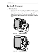
Page 14: ...4 DS400X and DS500X Digital Fishfinders...

Page 15: ...and packing in case you need to return a unit for service Check that you have all the correct system components These depend on your system package as follows Table 2 1 Supplied Parts Item Part No On...

Page 16: ...ure reliable and trouble free operation Access There must be sufficient space below the unit to enable cable connections to the panel connectors avoiding tight bends in the cable Interference The sele...

Page 17: ...the unit All cables should be adequately secured protected from physical dam age and exposure to heat Avoid running cables through bilges or doorways or close to moving or hot objects Avoid sharp bend...

Page 18: ...o not shorten or splice the cable Ifthetransducercableiscut itmustbereplaced itcannotberepaired Cutting the cable will also void the warranty Figure 2 1 DS400X Unit Dimensions 2 28 in 57 9 mm 5 88 in...

Page 19: ...Figure 2 2 DS500X Unit Dimensions 3 46 in 88 mm 5 88 in 149 4 mm 2 66 in 67 6 mm 3 08 in 78 3 mm 2 99 in 76 mm 2 83 72 m 6 37 in 161 8 mm 3 81 in 96 7 mm 5 9 in 150 mm 6 22 in 158 mm D6448 2 2 66 in...

Page 20: ...the display angle and tighten the knobs Console Mounting optional The fishfinder may also be installed directly into the console This requires thepurchaseofanoptionalFlushMountkit Raymarinepartnumber...

Page 21: ...ed at the rear of the unit 8 Place the gasket on the rear of the fishfinder 9 Run the Power NMEA cable and transducer cables through the back of the cutout and connect to the unit Avoid tight bends in...

Page 22: ...5 ft 1 5 m cable is supplied for connecting the boat s DC power and NMEAinterfacetotheunit ThisPower NMEAcablecanbeextendedby up to 60 ft 20 m using a wire gauge of AWG 12 or greater The cable s molde...

Page 23: ...off the drain wire A fast blow 2 amp fuse is attached in line to the red positive wire Figure 2 6 Installing the Fuse CAUTION If the power connections are accidentally reversed the system will not wor...

Page 24: ...Figure 2 3 CAUTION Do not pull on the cable This can damage the transducer wires Do not cut the transducer cable or remove the connector Donot try toshortenor splice the cable Cutting thetransducer ca...

Page 25: ...etails on setting up your DS400 500X and display are given in Chapter 6 3 3 Simulator Mode If you have not fully installed the fishfinder you can still operate in Simulator mode by connecting the fish...

Page 26: ...t can also indicate bottom structures such as a reef or shipwreck The upper and lower depth range limits are shown You can customize the sounder by choosing what is displayed and how it is displayed i...

Page 27: ...choes is indicated by different colors You can use this information to determine the size of fish and the bottom structure Other objects in the water such as debris and air bubbles also return echoes...

Page 28: ...depth of the target The closer the target to the surface the larger the image on screen To display the depth of individual targets switch on the TARGET DEPTH ID from the menu as described on page 44...

Page 29: ...n on the display TRACKPAD WhenaMenuitemhasmorethanonepossibleresponse usetheleftandright arrow keys to change the value When a menu item appears in UPPER CASE it contains sub menus Press the right arr...

Page 30: ...Using the Variable Range Marker VRM The VRM Variable Range Marker key is used to determine the distance behindtheboatofanobjectonthedisplay TheVRM functionisavailableon thescrollingsonardisplayandzoom...

Page 31: ...ge Displays sounder data This is the default screen it appears when you first power on the unit Temperature Graph Page Displaysagraphplottingwatertemperaturereadingsfromthetransducer over the past 60...

Page 32: ...ess to display Temp Screen 60 50 40 30 20 10 0 68 69 70 71 72 73 74 68 69 70 71 72 73 74 Minutes Temperature 71 5 F Speed kts 4 6 Log Trip 50 2 V 13 5 ft nm nm Position Waypoint m nm AM F V h SOG COG...

Page 33: ...6 Accessing the Main Menu Figure 3 6 identifies these groupings General Menu Controls are described in Chapter 4 Display Setup functions are described in Chapter 5 Sounder Setup functions are describ...

Page 34: ...A OUT SETUP Language Key Beep Key Help Depth Offset SOUNDER SETUP Speed Calibrate Temp Calibrate Sounder Simulator Speed Temperature Battery Log Trip Auto Scroll Analog Gauges SOG LAT LONG Waypoint RN...

Page 35: ...ge to the Gain setting To make changes to the menu settings 1 Press the MENU key The MAIN MENU screen appears The currently selected menu item in this case Scroll Speed is highlighted 2 Press the trac...

Page 36: ...is changed the change is accepted you need not use the ENTER key to select Range Frequency AUTOMATIC AUTOMATIC Scroll Speed ON A Scope OFF GAIN MODE ZOOM AUTO FISHING DISPLAY SET UP SOUNDER SET UP TR...

Page 37: ...n to the fish finder page GAIN MODE GAIN MODE COLOR GAIN Second Echo Rej AUTOMATIC GAIN AUTO TROLLING TVG AUTOMATIC Max Ping Rate Power Sounder Int Rej AUTO FISHING LOW AUTOMATIC 30 D6647 1 D6648 1 EN...

Page 38: ...e Menuitemsthataredisplayedinallcapsfollowedbyanellipsis GAIN MODE for example contains sub menus Use the trackpad keys to scroll through the sub menus 40 20 60 60 43 44 44 43 43 47 47 42 ft 35 36 Ran...

Page 39: ...uency AUTOMATIC 200 kHz MAN 50 kHz MAN DUAL MAN AUTOMATIC A Scope OFF ON 1 ON 2 ON 3 OFF GAIN MODE GAIN AUTO FISHING AUTO TROLLING AUTO CRUISING MANUAL 0 99 AUTO FISHING COLOR GAIN AUTOMATIC MANUAL 0...

Page 40: ...ely theRangesettingenablesyouto select themaximum depth displayed on the scrolling bottom and A Scope displays This parameter determines whether the depth range displayed is set automatically by the s...

Page 41: ...the change if desired Ifyouwish to remain in Automatic Range mode press QUIT The following range shift values are available The default setting is AUTOMATIC Table 4 2 Range Values Feet Fathoms Meters...

Page 42: ...wing This frequency is typically usedfor shallowerwater and amore detailed view When using this frequency the transducer scans a nar rower area but produces a more detailed view The 200 kHz signal is...

Page 43: ...lingbottom image in the left hand window Select one of the three modes for A Scope as demonstrated in Figure 4 1 OFF in whichA Scope doesnot appear ON 1 in whichthe image takesup the entire A Scope wi...

Page 44: ...that the setting contains sub menus Gain Mode is comprised of seven sub menus Gain Color Gain Time Variable Gain TVG Sounder Interference Rejection Int Rej Second Echo Rejection Power Maximum Ping Ra...

Page 45: ...l for slow speeds and drifting AUTO TROLLING is a medium gain setting that is better suited for trolling speeds AUTO CRUISING is the lowest automatic gain setting ideal for reducing background noise o...

Page 46: ...Increasing the TVG value increases the maximum depth to which TVG is applied Decreasing reduces the maximum depth Although you can manually set the TVG level Raymarine recommends letting the unit choo...

Page 47: ...ct from the following AUTOMATIC in which the sounder automatically determines the optimal power setting based on the current depth speed and bottom signal strength MANUAL in which the power is increas...

Page 48: ...e right hand window See Figure 4 3 In a split window display a zoom box appears representing the range being displayed in the zoom window The depths of the upper and lower boundaries of the zoom box a...

Page 49: ...the zoom window so that bottom details are always in view MANUAL enables you to reposition the zoomed image TRIP RESET This option resets the trip log Once TRIP RESET is selected you have the option t...

Page 50: ...40 DS400X and DS500X Digital Fishfinders...

Page 51: ...Display Set Up menu items 1 Press the MENU key The Main Menu appears 2 Press the trackpad keys to navigate to DISPLAY SET UP 3 Press the trackpad key or ENTER to select 4 Press the trackpad keys to b...

Page 52: ...N MODE ZOOM AUTO FISHING DISPLAY SET UP SOUNDER SET UP TRIP RESET MAIN MENU MAIN MENU Range Frequency AUTOMATIC AUTOMATIC Scroll Speed ON A Scope OFF GAIN MODE ZOOM AUTO FISHING DISPLAY SET UP SOUNDER...

Page 53: ...than 40 Target Depth ID OFF DEPTH FISH FISH DEPTH OFF Depth Digit Size LARGE SMALL LARGE Transparent Menu OFF ON OFF PALETTE Selection CLASSIC SUNBURST GRAYSCALE INV GRAY COPPER NIGHT VISION CLASSIC B...

Page 54: ...reen OFF displays neither the depth or a fish icon This is the default setting DEPTH displays the depth just above each target echo FISH displays a fish icon instead of an echo Three different fish ic...

Page 55: ...lower left of the screen Choose from the following LARGE default SMALL Transparent Menu This option removes the background white from the menu dialog box enabling you to see data that would normally b...

Page 56: ...usted over a wide range suitable for viewing in daylight high brightness level or at night low brightness level Selection Select the optimal color scheme for your lighting conditions CLASSIC default S...

Page 57: ...gularly used data in acompact form so that most of the graphics can still be seen Each data item can be displayed in a separate data field or scrolled through a single data field every three seconds S...

Page 58: ...Figure 5 4 Data Items Displayed as Analog Gauges NAV SET UP Navigation Data Similar to Data Items this is a list of navigation data you can display on the screen as separate data items Select from th...

Page 59: ...ffset Number of hours to offset the displayed time from the Universal Time Constant UTC otherwise known as Greenwich Mean Time Select UTC time or from 13 to 13 hours of UTC Time Format Display 12 HOUR...

Page 60: ...50 DS400X and DS500X Digital Fishfinders Figure 5 5 Displaying Navigation Data 40 20 60 60 D6903 1...

Page 61: ...system you may decide to customize some aspects At the end are displayed the serial number of your sounder and the software version running This information may be requested by Raymarine staff should...

Page 62: ...UP TRIP RESET MAIN MENU MAIN MENU Range Frequency AUTOMATIC AUTOMATIC Scroll Speed ON A Scope OFF GAIN MODE ZOOM AUTO FISHING DISPLAY SET UP SOUNDER SET UP TRIP RESET MAIN MENU MAIN MENU SOUNDER SET...

Page 63: ...F DEPTH FISH FISH DEPTH OFF Fish Alarm ON OFF OFF Shallow Alarm ON OFF OFF Shallow Range 2 1999 FEET 0 332 FATHOMS 1 608 METERS1 5 FEET 1 FATHOM 2 METERS1 Deep Alarm ON OFF OFF Deep Range 3 2000 FEET...

Page 64: ...S Bearing Mode TRUE MAGNETIC TRUE Date Format MM DD YY DD MM YY MM DD YY Time Format 12 HOUR 24 HOUR 12 HOUR NMEA OUT SETUP BWC BWR DBT DPT GLL MTW VHW VLW VTG ZDA OFF ON OFF Language ENGLISH UK ENGLI...

Page 65: ...e anchor drags and the boats moves into shallower or deeper water Note Afteryouhaveacknowledgedthe soundingofashallowordeepwater alarm a minimum of 30 seconds must elapse before a another shallow deep...

Page 66: ...etting the beeper sounds and moving arrow indicators point to the digital depth display You cannot set the shallow alarm to be deeper than the deep alarm The default setting is OFF Shallow Range Useth...

Page 67: ...the value set for Deep Range automatically enables the Deep Alarm Temp Alarm If this alarm is ON and the water temperature falls within the range set using the Temp Rng High and Temp Rng Low settings...

Page 68: ...TS parameter See page 59 ALARM CLOCK Set this alarm to sound the beeper at a particular time of day Note This function requires NMEA input of the current time To enable the Alarm Clock 1 Select highli...

Page 69: ...system Depth Units FEET default FATHOMS METERS Available in CE models only Temp Units FAHRENHEIT default CENTIGRADE Speed Units KNOTS default MILES PER HOUR KM PER HOUR Distance Units NAUTICAL MILES d...

Page 70: ...all NMEA sentences is transmission ON Disable the sentence by selecting OFF The following table displays the available NMEA sentences and their meanings 1 Data repeated from external device Table 6 2...

Page 71: ...pting you to make the appropriate key presses The help message is cleared when an action is selected ENGLISH UK ITALIAN ENGLISH US default NORWEGIAN DANISH PORTUGUESE FRENCH SPANISH GERMAN SWEDISH DUT...

Page 72: ...tes the Log Trip and paddlewheel distance Temp Calibrate If the transducer is equipped with a temperature sensing thermistor the DS400 500X calculates the temperature of the water The temperature cali...

Page 73: ...s a sealed unit Maintenance procedures are therefore limited to the following periodic checks Examine the cables for signs of damage such as chafing cuts or nicks Check that the cable connectors are f...

Page 74: ...hat service procedures and replacementpartsusedwillnotaffectperformance Therearenouserser viceable parts in any Raymarine product Some products generate high voltages so never handle the cables con ne...

Page 75: ...Check the system fuse Display freezes 1 Check the Scroll Speed is not set to PAUSE 2 Check the transducer cable for damage If damaged the cable and transducer must be replaced as a unit Unit does not...

Page 76: ...base Clicking the Find Answers link routes you to our solution database Search questions and answers by product category keywords or phrases If the answer you are seeking is not available click the As...

Page 77: ...port Specialists are available to answer questions about installing operating and trouble shooting all Raymarine products Questions can be sent directly to our Technical Support Department via the Int...

Page 78: ...Anchorage Park Portsmouth Hampshire England PO3 5TD Tel 44 0 23 9269 3611 Fax 44 0 23 9269 4642 Technical Support The Technical Services Department handles inquiries concerning installation operation...

Page 79: ...on condensing Power Input 10 0VDC to 18 0VDC 13 8 VDC nominal Consumption Typical 10W 12VDC Mounting Mounting Bracket or optional Flush Mount Controls 5 defined keys and trackpad Display 320 x 240 pix...

Page 80: ...70 DS400X and DS500X Fishfinders NMEA Data Connector Received Transmitted POWER NMEA BWC BWR GLL ZDA RMB VTG HDG HDT BWC BWR DBT DPT GLL MTW VHW VLW VTG ZDA...

Page 81: ...ort 66 D Data Items 47 Analog Gauges 47 Auto Scroll 47 Battery 47 Log 47 Speed 47 Temperature 47 Trip 47 Date Format 49 60 Date Setting 49 Deep Alarm 57 Deep Range 57 Depth Digit Size 45 Depth Offset...

Page 82: ...pad 19 L Language 61 LAT LONG 48 List Display Set Up Menu items 43 Main Menu items 29 Sounder Set Up Menu items 53 Location Mounting 6 Log 47 M Main Menu 25 List 29 Maintenance 63 Max Ping Rate 37 Men...

Page 83: ...37 Selecting Menu Items 25 Serial Number 62 Service 67 Shallow Alarm 56 Shallow Range 56 Simulator 15 62 Software Version 62 SOG 48 Sonar Basic System 2 Echoes 16 Image 17 Signal Strength 17 Target I...

Page 84: ...e 20 21 Temp Range 58 Temp Units 59 Temperature 47 Time Format 49 60 Time Offset 49 Time Setting 49 Trackpad 19 Transducer 3 Cable 14 Cleaning 63 Connections 12 14 Transparent Menu 45 Trip 47 Trip Res...

Page 85: ...DS400X Flush Mount Template TOP 90 mm Cut out with 3 5 8 hole saw Remove shaded areas only 2 99 76 mm 2 83 72 mm D6649 2...

Page 86: ...DS400 Mounting Template...

Page 87: ...DS500X Flush Mount Template TOP 90mm Cut out with 3 5 8 hole saw Remove shaded areas only 2 83 72mm 2 99 76 mm D6650 2...

Page 88: ...DS500 Mounting Template...

Page 89: ...returned to Raymarine or its approved national distributor with a copy of a Proof of purchase showing the date of purchase and the name of the seller of the product and the serial number of the affect...

Page 90: ...ess for a particular purpose and ii all obligations of Raymarine for damages including but not limited to accidental consequential or special damages including punitive or multiple or any financial lo...

Page 91: ...der Services Telephone 1 800 539 5539 Ext 2333 or 1 603 881 5200 Ext 2333 Customer Support Telephone 44 0 23 9271 4713 Fax 44 0 23 9266 1228 Technical Support Telephone 1 800 539 5539 Ext 2444 or 1 60...

Page 92: ...Warranty...

Reviews: