background image

INSTALLATION & OPERATION 

INSTRUCTIONS

i70 Instrument

Summary of Contents for i70

Page 1: ...INSTALLATION OPERATION INSTRUCTIONS i70 Instrument...

Page 2: ...imed trademarks of FLIR Systems Inc All other trademarks trade names or company names referenced herein are used for identification only and are the property of their respective owners This product is...

Page 3: ...25 4 1 General cabling guidance 26 Cable types and length 26 Routing cables 26 Strain relief 26 Cable shielding 26 4 2 Connections overview 26 Connecting SeaTalkng cables 26 SeaTalkng product loading...

Page 4: ...1 AIS Overview 64 10 2 AIS target symbols 65 10 3 Setting AIS Range 66 10 4 Viewing AIS target information 66 10 5 Enabling and disabling AIS Silent mode 67 Chapter 11 Race timer settings 69 11 1 Set...

Page 5: ...cers 104 18 5 Instrument Speed and Temperature transducers 104 18 6 Instrument Wind Vane transducer 105 18 7 Instrument Rotavecta transducer 105 18 8 Other transducers 106 18 9 SeaTalkng cables and ac...

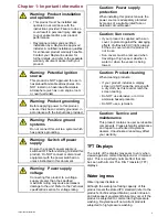
Page 6: ...e Technical specification section for voltage rating Caution Power supply protection When installing this product ensure the power source is adequately protected by means of a suitably rated fuse or a...

Page 7: ...mmendations always ensure the maximum possible separation between different items of electrical equipment to provide the best conditions for EMC performance throughout the installation Suppression fer...

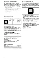
Page 8: ...tion Part number i70 Installation and operation instructions Installation and operation instructions for the i70 unit and connection to a wider system of marine electronics 81357 i70 Mounting template...

Page 9: ...3 2 Parts supplied on page 16 3 3 Software updates on page 17 3 4 Tools on page 17 3 5 Typical systems on page 18 3 6 System protocols on page 21 3 7 Warnings and cautions on page 21 3 8 General locat...

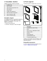
Page 10: ...e additions or maintenance of the system The diagram should include Location of all components Connectors cable types routes and lengths 3 2 Parts supplied The following parts are supplied with your p...

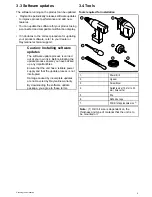
Page 11: ...carried out at your own risk Before initiating the update process ensure you have backed up any important files Ensure that the unit has a reliable power supply and that the update process is not int...

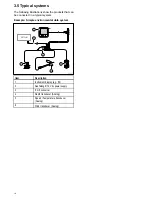
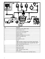
Page 12: ...t can be connected in a typical system Example Simple environmental data system Item Description 1 Instrument display e g i70 2 SeaTalkng 12 V dc power supply 3 iTC 5 converter 4 Depth transducer Anal...

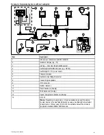
Page 13: ...aTalkng converter 8 Vessel Engine systems 9 iTC 5 converter 10 Rudder reference 11 Depth transducer Analog 12 Wind transducer Analog 13 Speed Temperature transducer Analog 14 ECI 100 Note Depending on...

Page 14: ...er 9 ACU Autopilot Control Unit 10 ECI 100 Note Depending on engine type it may be possible to connect the engine system directly to the SeaTalkng backbone using a SeaTalkng to DeviceNet adaptor cable...

Page 15: ...s can also be connected using the appropriate interfaces or adaptor cables as required NMEA 2000 NMEA 2000 offers significant improvements over NMEA 0183 most notably in speed and connectivity Up to 5...

Page 16: ...y compasses on your vessel Power to keep cable runs to a minimum the product must be located as close as possible to the vessel s dc power supply Mounting surface ensure the product is adequately supp...

Page 17: ...3 9 Product dimensions Item Description A 110 mm 4 33 B 115 mm 4 52 C 14 mm 0 55 D 30 mm 1 18 E 35 mm 1 38 F 90 mm 3 54 G 17 mm 0 67 Planning the installation 23...

Page 18: ...2 Connections overview on page 26 4 3 SeaTalkng power supply on page 27 4 4 Cable ferrite installation on page 29 4 5 SeaTalkng connection on page 30 4 6 NMEA 2000 network connection on page 31 4 7 Se...

Page 19: ...t carrying AC and DC power lines antennae Strain relief Ensure adequate strain relief is provided Protect connectors from strain and ensure they will not pull out under extreme sea conditions Cable sh...

Page 20: ...er rating 5A 3 A if only connecting one device Note The suitable fuse rating for the thermal breaker is dependent on the number of devices you are connecting If in doubt consult an authorized Raymarin...

Page 21: ...ible and more than 1 item of equipment shares a breaker use individual in line fuses for each power circuit to provide the necessary protection In all cases observe the recommended breaker fuse rating...

Page 22: ...nsure EMC Compliance the supplied ferrite must be fitted to the cable according to the following instructions 1 The ferrite must be fitted to the end of the cable closest to the device 2 The ferrite m...

Page 23: ...dc power supply 5 EV unit 6 SeaTalkng 5 way connector 7 Rudder reference transducer 8 iTC 5 converter 9 Depth transducer 10 Wind transducer 11 Speed transducer Example SeaTalkng SPX system with transd...

Page 24: ...nstrument 3 ST60 Speed instrument 4 ST60 Wind instrument 5 Wind transducer 6 SeaTalkng to SeaTalk Adaptor cable 7 Depth transducer 8 Speed transducer 9 Course computer supplying 12V to SeaTalk network...

Page 25: ...detailed installation instructions refer to documentation supplied with your pod Item Description 1 Speed and Temperature transducer 2 Speed pod 3 SeaTalkng T Piece connector 1 Connect the transducer...

Page 26: ...he cut edge until smooth 6 Drill four holes as indicated on the template to accept the securing screws 7 Peel the backing off of the gasket and place the adhesive side of the gasket onto the display u...

Page 27: ...nts 6 1 Instrument controls on page 36 6 2 Power on page 36 6 3 Completing the startup wizard on page 37 6 4 Display settings on page 37 6 5 Multiple data sources MDS overview on page 39 6 6 Quick Opt...

Page 28: ...ally turn on with the system unless it has previously been powered off using the Power button With the unit powered off 1 Press and hold the Power button until the screen turns on approximately 2 seco...

Page 29: ...e Up and Down buttons to adjust the brightness to the required level 3 Select Ok The Display Brightness page will time out after 2 seconds saving the new brightness level Shared Brightness You can set...

Page 30: ...ffect all units assigned to the same group Unsharing a unit Instrument Displays and Pilot Controllers can be removed from the Shared Brightness 1 Press the Power button to display the Shared Brightnes...

Page 31: ...are NOT MDS compliant It may be possible to upgrade the software for these products to make them compliant If MDS compliant software is not available for the product and you do NOT want to use the sys...

Page 32: ...eed Trip Reset Trip Max SOG Reset Max SOG Ave SOG Reset Ave SOG CMG DMG Reset CMG DMG Maximum Sea Temperature Reset Max Sea Temperature Minimum Sea Temperature Reset Min Sea Temperature Maximum Air Te...

Page 33: ...ontents 7 1 Transducer types on page 42 7 2 Depth calibration on page 42 7 3 Speed calibration on page 43 7 4 Wind calibration on page 48 7 5 Rudder reference calibration on page 50 7 6 Compass calibr...

Page 34: ...r the waterline or the bottom of your vessel s keel as appropriate Then set the appropriate depth offset value 1 Waterline offset Values greater than zero Positive values represent a waterline offset...

Page 35: ...Speed Calibration is all that is required If the 1 point calibration does not provide sufficiently accurate readings or you require a higher level of precision for your speed readings then a Speed Run...

Page 36: ...and Down buttons to adjust the current speed reading so that it matches the SOG reading or matches your estimated speed 11 Select Done when both values are the same The calibration complete page is di...

Page 37: ...A list of available transducer data is displayed 6 Select Speed Important Step only applicable to iTC 5 7 Select Speed Calibration 8 Select New cal using SOG You will need to add calibration points a...

Page 38: ...uracy water conditions should be calm with zero tide and zero current You will need to calibrate each calibration speed point starting with the lowest 1 In calm conditions with zero tide and zero curr...

Page 39: ...adjustment 9 Select Finish when all of the required Calibration Points have been adjusted Deleting a Calibration Point Calibration Points can be deleted from the Calibration Table From the Adjust cal...

Page 40: ...g or pitching too much From a favorite page 1 Select Menu 2 Select Set up 3 Select Transducers Set up 4 Select Continue The instrument display will search for and display a list of connected devices i...

Page 41: ...arent Wind Angle AWA should be 0 degrees 2 Select the device that the transducer s you are calibrating are connected to A list of available transducer data is displayed 3 Select Wind Important Step on...

Page 42: ...nected to an autopilot must be calibrated using the pilot controller Centering the Rudder Centering the Rudder requires a method of knowing the Rudder s actual position From a favorite page 1 Select M...

Page 43: ...lot must be calibrated using a Pilot Controller Swinging the Compass You will need to turn your vessel in slow circles while the system automatically makes adjustments to account for Compass Deviation...

Page 44: ...fset to the Compass heading by following the steps below To apply an offset you require a source of heading such as the ship s compass From the transducers found page 1 Ensure that the Rudder is centr...

Page 45: ...creen 1 Select Menu 2 Select Quick Options 3 Select Edit Page 4 Select the page that you want to edit 5 Use the Up and Down buttons to highlight the cell that you want to change 6 Press the Menu butto...

Page 46: ...age is now deleted Changing the page order From the Favorite Pages menu Menu Favorite Pages 1 Select Page order 2 Select the page you wish to move Page numbers are shown momentarily when you manually...

Page 47: ...ternator Potential Transmission Oil Pressure Transmission Oil Temperature Transmission 2 Engine Overview Data Category Favorite Page Data Items Quick View Data Items 1 Engine Overview 1 Engine Overvie...

Page 48: ...Items Navigation Active Waypoint Name Waypoint ID Course Made Good CMG DMG CMG VMG Distance Made Good BTW BTW DTW DTW XTE ETA TTG Course to Steer CTS XTE Rolling Road Turn Turn DTW Active Waypoint Nam...

Page 49: ...A VMG AWA Max AWA Min AWS AWS History AWS Max AWS Min Beaufort Cardinal GWD GWD History GWD Beaufort TWD TWD History TWA TWA History TWA TWS TWA CH TWS TWA VMG TWA Max TWA Min TWS TWS History TWS Max...

Page 50: ...age The Quick View data pages can be added as a Favorite page From the Data Quick View menu 1 Select the Data item so that it is displayed onscreen 2 Press the Menu button 3 Select Quick Options 4 Sel...

Page 51: ...these targets such as their position course speed and rate of turn Display basic or detailed information for each target vessel including safety critical target data Set up a safe zone around your ve...

Page 52: ...N position Aid To Navigation AToN target Real AToN target is OFF position Target red Aid To Navigation AToN target Real AToN target is OFF position dangerous Target black and flashes Aid To Navigation...

Page 53: ...ts With the AIS page displayed 1 Press the Menu button 2 Select Quick Options 3 Select View AIS targets 4 Use the Up and Down buttons to select an AIS target The Name of the vessel will be displayed i...

Page 54: ...sh to receive data from other vessels Note Not all AIS equipment supports silent mode For more information refer to the documentation that accompanied your AIS unit From the AIS page 1 Press the Menu...

Page 55: ...timer you want to adjust 11 2 Using the Race Timer With the Race Timer page displayed 1 Select Start The first star timer will begin to count down audible beeps are sounded as follows Double beep ever...

Page 56: ...will also be able to adjust settings Man over Board MoB alarm In the event of a MOB alarm the instrument provides details to help find the MoB target Brg Bearing to MoB waypoint Rng Range to MoB waypo...

Page 57: ...ngle low Adjust 0 180 10 de fault Alarm On Off de fault Wind TWS High True Wind Speed high Adjust 0 200 KTS 10 kts de fault Category Alarm Content Alarm On Off de fault Wind TWS Low True Wind Speed lo...

Page 58: ...Content Safety messages On Off de fault Dangerous target On Off de fault Safe zone 0 1 0 2 0 5 1 0 2 0 nm 0 1 0 2 0 5 1 0 2 0 sm 0 2 0 5 1 0 2 0 5 0 km Other AIS Alarm Time to safe zone 3 min 6 min 12...

Page 59: ...igure network groups and data sources Network group Bright ness Color Group Data Sources About System Set Up Simulator Enables and disables simulator mode The simulator produces simulated data to enab...

Page 60: ...plays can supply information about the installed transducer or interface such as Serial No and Software version etc Speed calibration speed settings are determined by the calibration points stored eit...

Page 61: ...ation of DT Depth and Temperature smart transducers and provides the following options DT800 details Depth offset Temperature offset DT800 details displays information about the installed transducer S...

Page 62: ...to specify the units used for the following key measurements Speed Distance Depth Wind speed Temperature Flow rate Heading Pressure Volume Barometric Speed kts knots mph miles per hour km h Kilometer...

Page 63: ...at Type Determines the default setup of the unit and favorite pages Race Sail Sail Cruiser Catamaran Workboat RIB Outboard Speedboat Inboard Speedboat Power Cruiser 1 12kts Power Cruiser 2 30kts Power...

Page 64: ...t Custom value Variation Enables you to turn on and off magnetic variation specify slave source or adjust manually Variation mode Variation range Variation mode On Off default Slave Variation range 30...

Page 65: ...1 Group 5 Brightness color group Enables synchronization of the displays brightness and color to be the same as the other units in the same group Sync brightness color This display This group Data sou...

Page 66: ...ion about the autopilot you are using Note The About Pilot menu is only available on Pilot controllers NMEA Code Product ID Serial number Description Software version PCB Number CAN Volts Unit Volts O...

Page 67: ...rvice and maintenance on page 86 14 2 Routine equipment checks on page 86 14 3 Product cleaning on page 87 14 4 Cleaning the display case on page 87 14 5 Cleaning the display screen on page 88 14 6 Cl...

Page 68: ...orized repair may affect your warranty 14 2 Routine equipment checks Raymarine strongly recommends that you complete a number of routine checks to ensure the correct and reliable operation of your equ...

Page 69: ...aled unit and does not require regular cleaning If it is necessary to clean the unit follow this basic procedure 1 Switch off the power to the display 2 Wipe the display with a clean soft cloth a micr...

Page 70: ...nsult your dealer Note Transducers with a temperature sensor may not work properly if painted Note Never use ketone based paint Ketones can attack many plastics possibly damaging the sensor Note Never...

Page 71: ...contents 15 1 Troubleshooting on page 90 15 2 Power up troubleshooting on page 91 15 3 System data troubleshooting on page 92 15 4 Miscellaneous troubleshooting on page 93 15 5 Performing a Factory R...

Page 72: ...prior to packing and shipping subjected to comprehensive test and quality assurance programs However if you experience problems with the operation of your product this section will help you to diagnos...

Page 73: ...are secure clean and free from corrosion replace if necessary 5 With the product under load using a multi meter check for high voltage drop across all connectors fuses etc replace if necessary Incorr...

Page 74: ...ment display or engine interface is not operating Refer to the manufacturer s handbook for the equipment in question Instrument engine or other system data is unavailable at all displays Software mism...

Page 75: ...problem with power to the display Check that the power source is of the correct voltage and sufficient current Software mismatch on system upgrade required Display behaves erratically Frequent unexpe...

Page 76: ...default settings follow the steps below Note Performing a factory reset will erase all saved data and customized settings 1 Press the Menu button 2 Select Set Up 3 Select Factory Reset 4 Select Yes Y...

Page 77: ...e Menu button 2 Select Set up 3 Select Diagnostics 4 Select About Display A range of information is displayed including the software version and Serial number 5 Use the Up and Down buttons to cycle th...

Page 78: ...Operating temperature 25 C to 55 C 13 F to 131 F Storage temperature range 30 C to 70 C 22 F to 158 F Relative humidity max 93 Water proof to IPX6 Display screen TFT LCD display 16bit color 64k colors...

Page 79: ...3 18 4 Instrument Depth transducers on page 104 18 5 Instrument Speed and Temperature transducers on page 104 18 6 Instrument Wind Vane transducer on page 105 18 7 Instrument Rotavecta transducer on p...

Page 80: ...can be connected directly to the SeaTalkng backbone without the need for an iTC 5 or transducer pod The smart transducers listed below are compatible with the following displays i70 i70s Multifunction...

Page 81: ...ducers listed below are compatible with the following instrument displays i40 Depth i40 Speed i40 Bidata i50 Depth i50 Speed i50 Tridata i70 i70s via iTC 5 converter Part number Image Mounting Housing...

Page 82: ...Thru hull P319 E26030 Thru hull P17 E26001 PZ In hull P79 A80373 T70278 in cludes SeaTal kng adap tor In hull P79S E26027 PZ Transom mount P66 18 5 Instrument Speed and Temperature transducers The sp...

Page 83: ...Image Housing Mounting E22078 Short arm wind vane Surface mount E22079 Long arm wind vane Surface mount 18 7 Instrument Rotavecta transducer The wind transducers listed below are compatible with the...

Page 84: ...040 1 x Power cable A06049 SeaTalkng Backbone Kit A25062 Includes 2 x 5m 16 4ft Backbone cable A06036 1 x 20m 65 6ft Backbone cable A06037 4 x T piece A06028 2 x Backbone terminator A06031 1 x Power c...

Page 85: ...ACU SPX SeaTalkng spur cable 0 3 m 1 0 ft R12112 Connects an SPX course computer or an ACU to a SeaTalkng backbone SeaTalk 3 pin to SeaTalkng adaptor cable 0 4m 1 3ft A06047 SeaTalk to SeaTalkng spur...

Page 86: ...connector A06064 Each connector block allows the connection of up to 3 compatible devices When correctly terminated a connector block forms a complete backbone Multiple connector blocks can be daisy c...

Page 87: ...A06036 2 5m 16 4ft Power cable A06049 1 1m 3 3ft Spur cable A06040 1 1m 3 3ft ACU SPX power cable R12112 for powering the SeaTalkng backbone from the autopilot system 1 0 3m 1 0ft 5 way connector A06...

Page 88: ...er kit E22158 Parts included Quan tity Connector A Cable Connector B Length Power cable A06049 1 1m 3 3ft Backbone terminator A06031 2 N A N A N A Blanking plug A06032 N A N A N A SeaTalk 3 pin adapte...

Page 89: ...Notes 3 way SeaTalk junction box D244 1 m 3 28 ft SeaTalk extension cable D284 3 m 9 8ft SeaTalk extension cable D285 5 m 16 4ft SeaTalk extension cable D286 9 m 29 5ft SeaTalk extension cable D287 12...

Page 90: ...Water Depth below transducer 128275 Distance Log 129025 Position Rapid Update 129026 COG SOG Rapid Update 129029 GNSS Position Data 129033 Time Date 129038 AIS Class A Position Report PGN Description...

Reviews: