
Raytheon Anschütz GmbH
Postfach 1166
D -- 24100 Kiel
Germany
Tel +49--4 31--30 19--0
Fax +49--4 31--30 19--501
Email Service@raykiel.com
www.raytheon--anschuetz.de
4002.DOC010102 Edition:
September 2014
NautoPilot 5000 Series
NP 5100
NP 5300
NP 5400
NP 5500
NautoPilot Operator Unit 102--890 NG001/NG002
Operator Manual
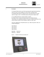
Description
Operation


