
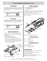

1. Determine the vertical centerline of the door lock face and
the horizontal centerline of the latch.
IMPORTANT
: When determining the horizontal centerline
observe the following:
FOR MORTISE LOCKS
: Align the angled ramps of the lip
bracket with the deadlock trigger of the mortise latch.
FOR CYLINDRICAL LOCKS
: Align the center of the latch with
the center of the strike opening.**
2. Transfer both the horizontal and vertical centerlines to the
doorframe.**
3. Prepare the doorframe for cutting as shown in the
appropriate drawing.
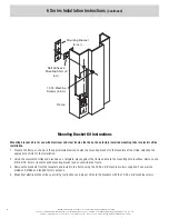
4. If required, install the ‘no weld’ mounting brackets per page 4.
5. Attach the strike faceplate to the lip bracket with the self-
tapping screws provided. (It may be desirable to leave these
screws slightly loose to facilitate insertion into the
doorframe.
6. Connect the incoming wiring from the power supply (see
wiring instructions).
7. Install the door strike in the doorframe using the screws
provided.
E
K
B
A
F
M
G
C
G
D
R
X
C
L
C
L
M
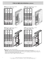
S6504
Aluminum & Wood Frames, 1-3/16" D
Modular
AS65
with
B604
faceplate
MEASUREMENT
FRACTIONAL
INCHES
DECIMAL
INCHES
METRIC
mm
A
1-1/4
1.250
31.75
B
4-7/8
4.875
123.83
C
3-3/8
3.375
85.73
D
1-3/16
1.188
30.16
E
3/8
.375
9.53
F
1/8*
.125*
3.18*
G 1-11/16
1.688
42.86
Vertical
Vertical
Vertical
X
C/L
C/L
C/L
Door
Door
Door
R
5/32
0.156
3.97
K
4-1/8
4.125
104.78
M
12-24
†
—
—
Vertical Centerline
of Door**
I N S T A L L A T I O N
Electric Strikes
6 Series
Instructions
E
K
B
A
F
M
G
C
G
D
R
X
C
L
C
L
M
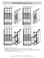
L6504
Aluminum & Wood Frames, 1-1/16" D
Modular
AL65
with
B604
faceplate
MEASUREMENT
FRACTIONAL
INCHES
DECIMAL
INCHES
METRIC
mm
A
1-1/4
1.250
31.75
B
4-7/8
4.875
123.83
C
3-3/8
3.375
85.73
D
1-3/32
1.094
27.78
E
3/8
.375
9.53
F
1/8*
.125*
3.18*
G 1-11/16
1.688
42.86
Vertical
Vertical
Vertical
X
C/L
C/L
C/L
Door
Door
Door
R
5/32
0.156
3.97
K
4-1/8
4.125
104.78
M
12-24
†
—
—
Vertical Centerline
of Door**
NOTE
: Specifications subject to change without notice.
*
Dimension F
is measured from face of mounting tab to face of frame and equates to the thickness of the faceplate.
**
Dimension X
on the drawing is determined by the vertical centerline of the door. If the latch incorporates a deadlocking pin additional steps will be neces-
sary to ensure proper operation of the deadlocking pin. Measure the thickness of the deadlocking pin and add this thickness to Dimension X to relocate the
vertical centerline an appropriate distance on the frame.
†
For wood frame door installations, substitute #12 wood screws for dimension M.
©2008 RUTHERFORD CONTROLS INT’L CORP. WWW.RUTHERFORDCONTROLS.COM
USA: 2697 INTERNATIONAL PARKWAY, PKWY 5, VIRGINIA BEACH, VA 23452 • CANADA: 210 SHEARSON CRESCENT, CAMBRIDGE, ON N1T 1J6
PHONE • 1.800.265.6630 • 519.621.7651 • FAX: 1.800.482.9795 • 519.621.7939 • E-MAIL: SALES@RUTHERFORDCONTROLS.COM
IS6A
PCN080047
P09/08DA
The L65 Low Profile version accepts 1/2” or 5/8” latch projection (perfect for narrow stile aluminum frames). The S65 Standard
version is ideal when you require 3/4" latch projection.


