background image

Original  Instruction  Manual
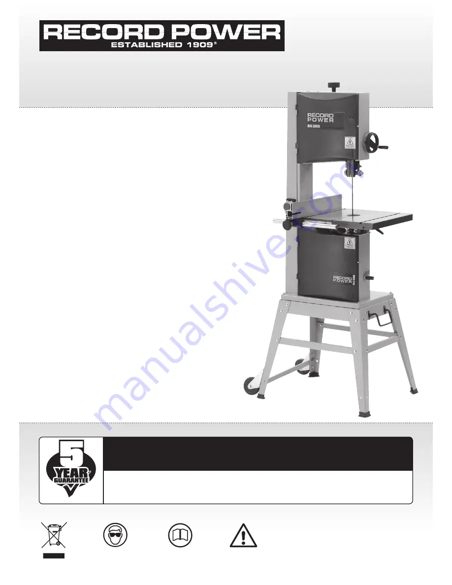
BS300E

 Premium 

12" Bandsaw

Always wear safety glasses when 
using woodworking equipment.

Always read the instructions 
provided before using 
woodworking equipment.

i

Kg

Version 3.0

January 2013

To register this product please visit

www.recordpower.info

It is important to register your product as soon as possible in order to receive efficient after sales 

support and be entitled to the full 

5 year guarantee

. Your statutory rights are not affected. 

Please see back cover for contact details.

Important

For your safety read instructions carefully 
before assembling or using this product.
Save this manual for future reference.

i

Kg

Summary of Contents for BS300E Premium

Page 1: ...ister this product please visit www recordpower info It is important to register your product as soon as possible in order to receive efficient after sales support and be entitled to the full 5 year guarantee Your statutory rights are not affected Please see back cover for contact details Important For your safety read instructions carefully before assembling or using this product Save this manual...

Page 2: ...rts Quick Find Blades BB931406 1 4 x 6 TPI Bandsaw Blade BB933806 3 8 x 6 TPI Bandsaw Blade BB931204 1 2 x 4 TPI Bandsaw Blade BB931206 1 2 x 6 TPI Bandsaw Blade BB933403 3 4 x 3 TPI Bandsaw Blade BB933404 3 4 x 6TPI Bandsaw Blade BB93CUS Custom width tooth pattern SBS300 127 Table Insert Band wheels SRPBS12 101 Drive belt SBS300 26 Band wheel tyre SBS300 18 Wheel bearing SBS300 58 Brush Upper Bla...

Page 3: ...ng to use the machine Indicates an instruction that requires particular attention Wear protective eyewear Use respiratory protective equipment Use suitable protective footwear Use hearing protection Use protective work gloves Indicates a risk of severe personal injury or damage to the machine Indicates a risk of severe personal injury from electrical shock Risk of personal injury from lifting of h...

Page 4: ...esigned to be fitted to the machine always ensure that it is securely fastened to the machine using the fixings provided If the machine is suitable to be used on a workbench ensure that the workbench is well constructed and capable of withstanding the weight of the machine The machine should always be securely fastened to the workbench with appropriate fixings Where possible floor standing machine...

Page 5: ...han the basic table or to help feed support or pull the work piece Do not attempt to machine more than one work piece at a time When feeding the work piece towards the blade or cutting tool never position your hands in direct line of the cutting path Avoid awkward operations and hand positions where a sudden slip could cause your hand or fingers to move into the machining area 23 Stay alert Safety...

Page 6: ...nsure that the teeth of the blade are pointing downwards Check the condition of the blade to ensure that no teeth are missing damaged or deformed and the blade is not cracked or split If any of these conditions apply replace the blade immediately Ensure that the saw blade type and width are suitable for the material to be cut Check that the blade width is within the minimum and maximum permitted o...

Page 7: ...n purchased from a retailer the 5 year guarantee is transferable and begins on the date of the first purchase of the Product and in the event of a claim under this guarantee proof of the original purchase date will be required to validate the warranty period 2 Claims Procedure 2 1 In the first instance please contact the Authorised Dealer who supplied the Product to you In our experience many init...

Page 8: ...ng Knob O Motor Rating Plate P 100 mm Dust Extraction Port Q Motor Blade length 2370 mm 93 Blade width 6 19 mm 1 4 3 4 Max depth of cut 190 mm Throat depth 305 mm Table size 480 x 400 mm Max width blade to rip fence 230 mm Table height 990 mm Extraction port 100 mm Motor 230 V 50 Hz 1 hp 750 W Full load current 4 6 A Weight 85 kg Footprint 700 x 540 mm Dimensions Height 1670 mm x width 680 mm x de...

Page 9: ...eel kit comes as a self assembly unit Fig 3 1 Stand 1 2 x Long mid brace supports 2 Medium mid brace support 3 Short mid brace support 4 2 x Long top brace supports 5 2 x Short top brace supports 6 4 x Legs 7 24 x Stand fixing nuts bolts and washers each Wheel Kit 8 8 x Hex bolts 9 2 x D Handle brackets 10 8 x Nylon nuts 11 8 x Washers 12 D handle 13 2 x Casters 1 3 2 4 5 6 7 8 9 10 11 12 13 Fig 3...

Page 10: ...hers supplied Fig 3 2 2 In the same way attach the second leg to the brace support Fig 3 3 3 Locate the short top brace supports and fix to the legs as shown Fig 3 4 4 Continue in this way until all of the legs and top brace supports have been fitted Fig 3 5 5 The locating holes a third of the way down each leg are for securing the mid brace supports Fix the long mid brace supports to the frame us...

Page 11: ...lts Washers and M6 Nuts provided Fig 3 9 3 Fully tighten all of the fixings to secure the wheels and handle assembly take care not to over tighten the fixings as damage to the threads may occur PLEASE NOTE For your safety only use the handle to pull the machine It is unsafe to push the machine using the handle When lifting the stand ensure the front legs are not raised higher than 200 mm from the ...

Page 12: ...ith the remaining washers and nuts Fig 3 11 Fig 3 10 LONG FIXING BOLTS 1 Feed the long fixing bolts up through the stand and secure the four corners using the washers and bolts provided Fig 3 10 The whole stand can now be fully tightened ready for the bandsaw to be fitted i Kg i Kg Fig 3 11 200mm 17º WARNING For your safety only use the handle to pull the machine It is unsafe to push the machine u...

Page 13: ... 1 1 2 5 4 6 1 2 x Nuts and 1 x small crank handle 2 Rise fall hand wheel 3 Blade tensioning knob Table Assembly 4 Fence scale 5 4 x Table fixing bolts nuts and washers 6 4 x Long fixing bolts nuts and washers 7 Table 8 Table levelling nut and bolt 9 Keep plate already fitted to underside of table Fence Assembly 10 4 x nuts 11 Fence bar 12 Fence carrier 13 Fence lock knob 14 2 x mounting blocks 15...

Page 14: ... crank handle to belt tension and speed mechanism with 10mm spanner not supplied See Fig 4 3 4 4 Fitting the table Tools Required 13mm spanner not supplied With the help of another person lift the working table onto the trunnion Mount the working table on the trunnion using the supplied 4 x table fixing bolts and 4 x washers See Fig 4 4 front view 4 5 rear view 4 5 Fitting the tension knob To fit ...

Page 15: ...tor Fig 4 8 4 Replace and re tighten the locking nuts 5 Position the slide underneath the protractor so that the threaded bar sits in the angle slide and the pivot pin inserts into the pivot hole Fig 4 9 and Fig 4 10 6 Tighten the ratchet handle onto the threaded bar Fig 4 10 4 Machine Assembly cont Fig 4 7 Fig 4 8 Fig 4 9 Fig 4 10 Mitre Fence Fence Screws Locking Nuts Protractor Slide Angle Slide...

Page 16: ...ixing nuts Use the 2 remaining nuts and washers to secure the fence bar from the underside of the table Fig 4 12 Do not fully tighten yet as adjustment may be necessary 4 8 Fixing the fence scale Attach the fence scale to the table Fig 4 13 and fix with the two hex socket screws Fig 4 11 FENCE BAR Fig 4 12 Fig 4 13 FIXING NUTS WASHERS HEX SOCKET SCREWS ...

Page 17: ...he mitre fence t slot by turning the adjustment collars and the fence bolts accordingly If the fixing nuts have been tightened these will need slackening off before this adjustment can be made see Fig 4 16 PLEASE NOTE The fence bar can be located to either the left or right hand side of the table allowing the fence to be used either side of the blade 4 12 Fence alignment 2 Check that the fence is ...

Page 18: ... contact with the top surface of the lower band wheel housing Once the stop screw is set to the correct length it is secured by tightening the lock nut up to the flat registration point on the underside of the table 5 2 Adjusting the table tilt scale Once the table is set at 90º to the bandsaw blade it may be necessary to adjust the angle pointer on the angle scale so any further angles are accura...

Page 19: ...ade guides Once the blade is tensioned track the blade by turning the upper band wheel by hand and adjusting the tracking knob See Fig 6 3 When viewed from the back of the machine turning the tracking knob clockwise the blade will move towards the back of the band wheel by turning the tracking knob anti clockwise the blade will move to the front of the band wheel The blade should run as close to t...

Page 20: ... of the blade Next set the roller guides as near as possible to the blade without actually touching This is done by releasing the hex head socket screw See Fig 6 9B on each side of the blade Finally adjust the rear thrust bearing to be just clear of the back of the blade See Fig 6 10 To do this first unlock the Hex socket screw See Fig 6 9C then using the adjustment knob at the rear position the t...

Page 21: ...or wood and 380 m min for some plastics and acrylics This machine is not suitable for cutting metals The lower band wheel has two integral multi vee form pulleys and the motor shaft has a twin multi vee form pulley The vee belt passes around the band wheel pulley the motor pulley and the plain tension roller The belt tension is released and applied by using the crank handle this moves the tension ...

Page 22: ...ad etc that should be investigated by a qualified electrician before attempting to restore the power source If a cutting operation was taking place when the power supply was interrupted then it may be necessary to free the blade from the work piece before attempting to re start the machine Once the power is restored the machine can be re started by pressing the green button marked I on the switch ...

Page 23: ... blade is too wide for the cutting radius the blade will twist and possibly jam or break The smaller the radius the narrower the blade has to be The diagram below provides guidance on the minimum radius to be cut with the most commonly used blade widths Blade width 3 8 Min radius 21 2 Blade width 1 4 Min radius 11 16 Blade width 1 2 Min radius 31 4 Material Material Thickness 6mm 6 12 mm 12 25 mm ...

Page 24: ...uctural analysis results in a blade that cuts straighter and has harder longer lasting teeth A premium British blade that can last up to ten times longer than other blades on the market The following range of blades are available for the BS300E Application Narrow Blade Wide Blade Application Application TIGHT CONTOUR MEDIUM CONTOUR STRAIGHT CUT LARGE CONTOUR Material Thick Soft Timber Blade Spec B...

Page 25: ...r vee block Take extreme care as there is a danger that if the work is not secured properly the blade will snatch the work piece potentially causing it to spin or bounce back at you Ex 3 Use a side pressure pad for accurate cutting of taller material 180 100 20 120 Ex 4 Chamfered pieces can be cut squarely using an additional support jig on the opposite side of the work piece to the fence Ex 5 Jig...

Page 26: ...f one motor is switched off for 20 minutes then the other can be used thus enabling continuous usage Or both motors can be used simultaneously giving maximum suction but in this mode the extractor must be switched off for 20 minutes every hour 0 5 micron filtration DX5000 High Filtration Dust Extractor Bag type extractor 200 litre capacity Twin 1 kW motor suitable for heavy usage ie if one motor i...

Page 27: ...ce on band wheel Simply re apply tension using the tension knob until the tension indicator shows the correct tension for the blade width Adjust the blade tension further if required using the blade tension knob 6 Check the blade tracking on the newly fitted blade by turning the upper wheel by hand The blade should run as close to the centre of the band wheel as possible On 1 4 3 8 and 1 2 blades ...

Page 28: ...accessed and replaced Undo the relevant cap head allen screws for either the guide rollers or rear support roller Fig 10 6 and fit the new parts Once the new components are fitted The blade should be re fitted Section 10 1 and the guides adjusted as shown in Section 6 When replacing components on the lower guide assembly first ensure that the blade is removed Undo cap head allen screws C D and rem...

Page 29: ...ion you will notice that there are two separate bearings fitted in the hub pressed up against each other Take a brass drift or similar and tap one of the bearings out the second bearing should now be able to be pushed out When fitting the new bearings position by hand in the wheel hub and tap in until the bearing seats against the ridge in the casting Fig 10 11 10 7 Cleaning the table The table is...

Page 30: ...ccurate The blade tension indicator is only a guide but tension is incorrect fine adjustment may be required for each blade Unsure of which type of blade to use Refer to section 9 in the manual How much tension should be Refer to section 9 in the manual put on the blade Cannot get the blade on Blade tension not released Ensure you have fully released the blade tension knob before trying to remove ...

Page 31: ...t be an earth wire within the circuit In the case of the BS1363 plug for use in the UK always ensure that it is fitted with a fuse conforming to BS1362 appropriate to the rating of the machine If replacing the original fuse always fit a fuse of equivalent rating to the original Never fit a fuse of a higher rating than the original Never modify the fuse or fuse holder to accept fuses of a different...

Page 32: ... nut 9 Washer 10 Hex bolt 11 Long mid brace support 12 Short top brace support 13 D handle 14 4 x pan head screws Stand with wheel kit 13 14 15 16 20 17 21 18 19 22 23 24 25 Ref No Description 15 2 x D handle clamps 16 Hex nut 17 Wheel bracket 18 Hex bolt 19 Hex nut 20 Flat washer 21 Washer 22 Carriage bolt 23 Flat washer 24 Wheel 25 Washer 13 Parts Diagrams 3 3 3 4 14 15 ...

Page 33: ...33 13 Parts Diagrams cont ...

Page 34: ...34 13 Parts Diagrams cont ...

Page 35: ...35 13 Parts Diagrams cont ...

Page 36: ... screw M6 1 0 x 20 51 Bushing 54 Hex nut 55 Upper wheel cover 56 Hex bolt M6 1 0 x 25 57 Flat washer M6 58 Brush 60 Star knob 61 Nylon nut M6 1 0 62 Strain relief 63 Strain relief nut 64 Crank handle 65 Crank 66 Guide post lock knob 67 Blade tracking knob 68 Wing nut M8 75 Hex nut 76 Sliding shaft 77 Tension wheel 78 Set collar 10mm 79 Hex screw 80 Hex nut 81 Lower wheel shaft 81 Motor 84 Lock was...

Page 37: ...r blade guide bracket 146 Blade support shaft 148 Pin roll 149 Hex socket screw 150 Adjust bar 151 Roller guide 153 Upper guide support block 154 Pan head screw 156 Rack 157 Upper guide hose 159 Hex socket screw 160 Bushing 161 Bushing 162 Cap screw M6 1 0 x 16 163 Spring washer 6 164 Guide bracket 165 Worm cylinder 166 Fixed plate 167 Gear 168 Fixed bolt 169 Cover 170 Hex bolt M8 1 25 x 16 171 Pa...

Page 38: ... using one of the pins and washers provided Fig 15 6 5 Feed the axle through the fixing holes on both of the rear legs of the stand and pedal Fig 15 7 The rear side of the machine is that which is closest to the spine see Fig 15 8 6 Repeat this process at the opposite side ensuring that both sides of the axle have been secured with the fixing pins and washers and that both sides of the pedal are f...

Page 39: ...TTENED AREAS Fig 15 6 FIXING PIN Fig 15 10 RELEASE CATCH PEDAL OPERATING FRAME Fig 15 9 Fig 15 5 AXLE BRACE SUPPORT BAR Fig 15 11 Fig 15 7 AXLE FIXING PIN PEDAL Fig 15 3 RELEASE CATCH Fig 15 4 Fig 15 8 REAR OF BANDSAW ...

Page 40: ...E 2006 95 EC and its subsequent amendment ELECTROMAGNETIC 2004 108 EC COMPATIBILITY DIRECTIVE EN 55014 1 2006 EN 61000 3 2 2006 EN 61000 3 3 1995 A1 A2 EN 55014 2 1997 A1 and its subsequent amendments and conforms to the machinery example for which the EC Type Examination Certificate No BM50169546 AN50169545 AE 50172130 has been issued by TÜV Rheinland Product Safety GmbH at Am Grauen Stein D 5110...

Page 41: ... uk Eire Record Power Ltd Unit B Adelphi Way Ireland Industrial Estate Staveley Chesterfield Derbyshire S43 3LS Tel 01246 561 520 www recordpower co uk Australia Tools 4 Industry Po Box 3844 Parramatta 2124 Tel 1300 124 422 Fax 1800 262 725 www recordpower com au New Zealand Tools 4 Industry Po Box 276079 Manukau City 2241 Tel 0800 142 326 Fax 09 2717 237 www recordpower co nz Made in China ...

Reviews: