background image

1

Original  Instruction  Manual

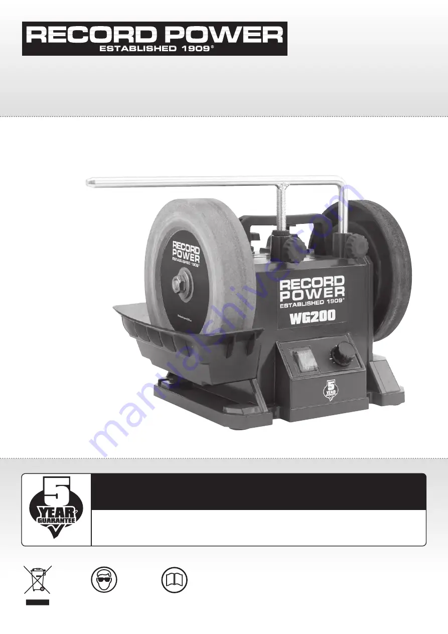
WG200

 Wet Stone Sharpening System

Important

For your safety read instructions carefully before 
assembling or using this product.
Save this manual for future reference.

Always wear safety glasses when 
using woodworking equipment.

Always read the instructions 
provided before using 
woodworking equipment.

i

Kg

Version 3.1

September 2016

To register this product please visit

www.recordpower.info

It is important to register your product as soon as possible in order to receive efficient after sales 

support and be entitled to the full 

5 year guarantee

. Your statutory rights are not affected. 

Please see back cover for contact details.

Summary of Contents for WG200

Page 1: ... using woodworking equipment Always read the instructions provided before using woodworking equipment i Kg Version 3 1 September 2016 To register this product please visit www recordpower info It is important to register your product as soon as possible in order to receive efficient after sales support and be entitled to the full 5 year guarantee Your statutory rights are not affected Please see b...

Page 2: ...pener 10 1 WG250 A Gouge Jig 10 2 WG250 B Short Tool Jig 10 3 WG250 C Straight Edge Jig 10 4 WG250 D Plane Camber Jig 10 5 WG250 E Scissor Jig 10 6 WG250 F Side Wheel Sharpening Jig 10 7 WG250 G Short Knife Jig 10 8 WG250 H Long Knife Jig 10 9 WG250 I Tool Rest Jig 10 10 WG250 J Axe Jig 10 11 WG250 O Support Arm Extension Kit 10 12 WG250 N Profiled Leather Honing Wheel 11 Maintenance 12 Troublesho...

Page 3: ... to use the machine Indicates an instruction that requires particular attention Wear protective eyewear Use respiratory protective equipment Use suitable protective footwear Use hearing protection Use protective work gloves Indicates a risk of severe personal injury or damage to the machine Indicates a risk of severe personal injury from electrical shock Risk of personal injury from lifting of hea...

Page 4: ...portation of the machine is required then all precautions relating to the installation and handling of the machine apply In addition ensure that any vehicles or manual handling equipment used for transportation are of adequate specification 6 The machine should be level and stable at all times When using a leg stand or cabinet base that is designed to be fitted to the machine always ensure that it...

Page 5: ...the blade or cutting tool The push stick should have a minimum length of 400 mm If the push stick becomes damaged replace it immediately Use extra supports roller support stands etc for any work pieces large enough to tip when not held down to the table top Do not use another person as a substitute for a table extension or as additional support for a work piece that is longer or wider than the bas...

Page 6: ... by a qualified person 31 Warning The use of any accessory or attachment other than those recommended in this instruction manual or recommended by our Company may present a risk of personal injury or damage to the machine and invalidation of the warranty 32 Have your machine repaired by a qualified person This machine complies with the relevant safety rules and standards appropriate to its type wh...

Page 7: ...running Check the condition of the stone If damaged or cracked replace the stone immediately Rotate the stone by hand to ensure that it can move freely without interference from other components Check that the speed control is set to correspond with the diameter of the sharpening stone mounted on the machine 4 Whilst sharpening honing When the machine is first switched ON allow it to run for up to...

Page 8: ... been purchased from a retailer the 5 year guarantee is transferable and begins on the date of the first purchase of the Product and in the event of a claim under this guarantee proof of the original purchase date will be required to validate the warranty period 2 Claims Procedure 2 1 In the first instance please contact the Authorised Dealer who supplied the Product to you In our experience many ...

Page 9: ... 200 x 40 mm Stone bore 12 mm Honing wheel size 180 x 30 mm Honing wheel bore 12 mm Speeds 120 250 rpm 1 25 2 6 M second Weight 8 5 kg 1 WG200 Wet Stone Sharpener 2 WG250 C Straight Edge Jig 3 WG250 K Diamond Trueing Tool 4 WG250 R Stone Grader 5 WG250 T Angle Setting Gauge 6 WG250 U Angle Finder 7 WG250 P Support Arm 8 WG250 S Honing Compound 9 Water trough 1 2 3 4 5 6 7 8 9 ...

Page 10: ...our Machine 1 Speed control knob 2 On off switch 3 Water trough 4 200 mm 8 sharpening stone 5 Support arm 6 Torque control knob 7 Support arm micro adjustment collar 8 Carrying handle 9 Leather honing wheel 3 4 5 8 9 7 6 2 1 ...

Page 11: ... arm to the upper brackets as shown in Fig 8 1 Install the water trough to the machine as shown in Fig 8 3 the stone has been removed only to allow the holes to be seen by hooking the brass brackets shown in Fig 8 4 into the lower set of holes on the side of the machine The upper holes are to be used when the stone has reduced in size through wear and it is too small to come into contact with the ...

Page 12: ...plied with a shaft extension and 2 washers as shown in Fig 8 5 Remove the knob that holds the honing wheel to the machine as shown in Fig 8 6 Fit the shaft extension as shown in Fig 8 7 Fit the profiled honing wheel to the shaft as shown in Fig 8 8 with a washer on either side and re fit the knob Apply mineral oil and honing paste before use ...

Page 13: ...rough is left on the bottom of the wheel will sit in water and become unbalanced Trueing the Stone The stone should be trued before use so it is parallel with the support arm as shown in Fig 9 3 This will ensure accurate results If the stone is new it may already appear parallel to the support bar but it is recommended to carry out the trueing procedure regardless as any inaccuracies that are not ...

Page 14: ...he tip slightly and repeat until continuous contact is achieved The stone must also be trued to be concentric to its shaft To achieve this true the stone until the tip of the tool touches across the stone s full circumference as well as its full width As the trueing tool is used the tip will wear To ensure even wear across its surface it can be rotated by loosening the securing screw as shown in F...

Page 15: ...9 13 and place the plane blade into the jig with the surface to be sharpened pointing downwards as shown in Fig 9 14 Align the side of the blade with the registration tabs on the jig as shown in Fig 9 13 This will ensure the edge to be sharpened is at 90º to the stone Re tighten the locking knobs Mount the support arm in the upper position and place the jig on the support arm Fig 9 14 Place the an...

Page 16: ...ineral oil is available as part of the WG250 X Maintenance Kit If the maintenance kit is not available then an alternative mineral oil can be used The oil will stop the honing paste from soaking deep into the leather Do not apply lubricating oil to the honing wheel Carefully apply honing paste to the wheel using a clean rag or sponge as shown in Fig 9 18 until even coverage is achieved Place the s...

Page 17: ...d rectify the source of the blockage If the work piece has become trapped between the sharpening stone and the jig the surface of the stone may become damaged It may be necessary to dress or true the stone before attempting to use the stone again Check that the sharpening stone can be turned freely by hand before attempting to re start the machine Re start the machine by pressing the green button ...

Page 18: ...n on the Record Power jig range or to purchase please contact your local retailer or visit the Record Power website WG250 B Short Tool Jig WG250 A Gouge Jig WG250 C Straight Edge Jig WG250 D Plane Camber Jig WG250 E Scissor Jig WG250 F Side Wheel Sharpening Jig WG250 G Short Knife Jig WG250 H Long Knife Jig WG250 I Tool Rest Jig WG250 J Axe Jig WG250 N Profiled Leather Honing Wheel WG250 O Support...

Page 19: ...head socket screw located in the elbow joint For shorter side bevels such as those found on bowl gouges lock the shaft in the uppermost position and for longer bevels as on spindle gouges lock the shaft in lower positions See Fig 10 1 2 Please note this should be done before setting the position of the tool to the correct bevel angle as any adjustments of the shaft after this will change the bevel...

Page 20: ... be used to set the correct sharpening angle Hold the jig against the support arm as shown in Fig 10 2 1 For most carving tools and other thin edge tools it is advisable to grind away from the edge of the tool for increased control Apply the tool to the stone as shown in Fig 10 2 1 and rotate the jig to sharpen the tool s edge Use to sharpen Small carving tools Small gouges V tools Fig 10 1 5 Fig ...

Page 21: ...on Place the tool into the jig and ensure it is resting against the registration bar as shown in Fig 10 3 1 Tighten both lock knobs equally to ensure the tool remains parallel to the jig Slide the straight edge jig on to the support arm and move the tool slowly from side to side across the sharpening stone as shown in Fig 10 3 2 Use to sharpen Plane irons Bevel edge chisels B A C Fig 10 3 2 Fig 10...

Page 22: ...lace using the blade lock knobs Ensure the camber lock knobs are released to allow the camber plate to move as shown in Fig 10 4 3 To set the desired camber position the camber setting screw as required and secure in place with the lock as shown in Fig 10 4 3 The depth of camber will increase when the screw is set in the lower positions Both camber setting screws and locks must be set equally to a...

Page 23: ...ge to the blade as shown in Fig 10 4 6 Using the Plane Camber Jig to Sharpen a Straight Edge Blade The jig can also be used to sharpen straight edge blades With the camber plate parallel to the base plate of the jig secure it in place using the camber lock knobs as shown in Fig 10 4 7 The blade can then be sharpened to produce a straight edge Fig 10 4 5 Fig 10 4 6 Fig 10 4 7 Camber plate Camber lo...

Page 24: ...n in Fig 10 5 1 and tighten the depth screw and clamp knob Secure the scissor blade in the clamp as shown in Fig 10 5 2 so the bevelled edge is facing the rear of the jig Mount the support arm in the upper position Slide the support plate onto the support arm as shown in Fig 10 5 3 and secure in position at an angle that allows the bevelled edge of the blade to come into full contact with the ston...

Page 25: ...1 Fig 10 6 2 B A Using the Side Jig Mount the support arm in the side position attach the jig as shown in Fig 10 6 1 and secure in place with the lock knobs Attach the WG250 I Tool Rest Jig as shown in Fig 10 6 2 at 90º to the side of the stone and sharpen as shown Pass the blade across the stone to sharpen the bevelled edge tilting the jig if necessary to follow the curve of the blade Fig 10 5 5 ...

Page 26: ... shown in Fig 10 7 2 Adjust the height of the support arm until the blade of the knife meets the stone at the required angle The fine adjustment knob can be used to alter the position of the stop to achieve the most accurate angle possible Pass the blade across the stone to sharpen the bevelled edge tilting the jig if necessary to follow the curve of the blade Use to sharpen Knives up to 100 mm 4 ...

Page 27: ...8 1 and secure the blade in place ensuring the cutting edge is as parallel to the clamp as possible Rest the stop of the jig on the support arm as shown in Fig 10 8 2 Adjust the height of the support arm until the blade of the knife meets the stone at the required angle The fine adjustment knob can be used to alter the position of the stop to achieve the most accurate angle possible Pass the blade...

Page 28: ...n either the upper or lower position A Lock knob B Face Fig 10 9 1 A B Using the Tool Rest Jig Mount the support arm in the side position Slide the tool rest jig on to the support arm and fix in place with the lock knob as shown in Fig 10 9 1 The required angle can be set using the position of the support arm and of the jig itself Rest the tool on the jig and apply to the sharpening stone as shown...

Page 29: ... arm of the wet stone sharpener Fig 10 10 1 Using the Axe Jig Mount the support arm in the upper position and slide the axe jig onto it as shown in Fig 10 10 1 Hold the axe head in the jig and tilt the axe blade slowly back and forth across the sharpening stone Turn the axe head over and repeat the process ...

Page 30: ... on tool such as woodturning roughing gouges With the support arm mounted in the side position apply the tool to the wheel as shown in Fig 10 12 1 Always hone with the wheel moving away from the blade to avoid damage to the leather Using the Extension Arm Place the extension arm holder onto the support arm ensuring the threaded hole is facing the opposite direction of the support arm and secure in...

Page 31: ...ushes in pairs Replacing the Sharpening Stone When the sharpening stone has worn to a diameter of approximately 100 mm 4 it must be replaced Disconnect the WG200 from the power source Loosen the nut and remove the stone Please note The lock nut has a left hand thread and must be turned clockwise to loosen Always use a genuine Record Power replacement stone Before mounting the wheel it must be chec...

Page 32: ...mond trueing tool to make the wheel concentric to its shaft Sharpening surface is not flat 1 Worn Sharpening stone grit 2 Static grinding 1 Use stone grader or diamond trueing tool to correct the wheel s surface 2 Move the tool across the stone as you grind for even wear of the stone Sharpening surface is poor 1 Worn stone 2 Leather honing wheel is dry 3 Application pressure of tool is too high 1 ...

Page 33: ...lways ensure that it is fitted with a fuse conforming to BS1362 appropriate to the rating of the machine If replacing the original fuse always fit a fuse of equivalent rating to the original Never fit a fuse of a higher rating than the original Never modify the fuse or fuse holder to accept fuses of a different type or size Where the current rating of the machine exceeds 13 A at 230 V or if the ma...

Page 34: ... QT9800 D QT9800 E QT9800 F QT9800 Explode Drawing Part No Description Quantity QT9800 A Machine body assembly 1 QT9800 B Motor assembly 1 QT9800 C Arm support assembly 1 QT9800 D Switch box assembly 1 QT9800 E Drive assembly 1 QT9800 F Water tank assembly 1 ...

Page 35: ...on Quantity A 01 Self tapping screw ST5 x 20 2 A 02 Handle 1 A 03 Torque adjusting knob M8 x 35 mm 1 A 04 Lock knob M6 x 12mm 4 A 05 Machine body 1 A 06 Slide bearing 2 A 07 Rubber foot 4 A 08 Self tapping screw ST4 x 14 2 A 09 Lock wire plate 1 A 10 Power cord 1 A 11 Tube 18 x 12 2 x 40 mm 2 A 12 Tube fixed bracket 2 A 13 Self tapping screw ST4 x 12 1 A 14 Machine support plate 1 A 15 Set nut M8 ...

Page 36: ...sh holder 2 B 06 Motor rear bracket cover 1 B 07 Screw M5 x 100 2 B 08 Flat Washer Ø5 2 B 09 Spring Washer Ø5 2 B 10 Spring Ø12 x 80 mm 1 B 11 E clip 2 B 12 Motor shaft 1 B 13 Bearing 2 B 14 Motor armature 1 B 15 Armature field 1 B 15 Magnetic shoe 2 B 16 Motor front bracket 1 QT9800 C Support Arm Assembly Part No Description Quantity C 01 Support arm 1 C 02 Micro adjustment nut 1 Part No Descript...

Page 37: ... Brown wire 80 mm 1 D 08 Blue wire 80 mm 1 E 01 Left hand nut M12 x 1 75 1 E 02 Washer 3mm for stone 2 E 03 Stone wheel 1 E 04 Main shaft 2 E 05 Spring pin Ø4 x 40 mm 2 E 06 Flat washer Ø12 x Ø24 x 1 5 2 E 07 Drive wheel 1 E 08 Lock nut 1 E 09 Honing wheel with Leather strip 1 E 10 Honing wheel Lock knob M12 1 14 Parts Lists and Diagrams Part No Name Description Quantity Part No Name Description Q...

Page 38: ...4XA declares that the machinery described 1 Type Wet Stone Sharpener 2 Model No WG200 3 Serial No Conforms with the following directives Machinery Directive 2006 42 EC EN61029 1 2009 A11 EN ISO 12100 2010 AfPS GS 2014 01 Issued by TÜV Rheinland LGA Products GmbH Tillystrasse 2 90431 Nürnburg Signed Dated 01 09 2016 Andrew Greensted Managing Director ...

Page 39: ...39 ...

Page 40: ... Power Ltd Centenary House 11 Midland Way Barlborough Links Chesterfield Derbyshire S43 4XA Tel 44 0 1246 571 020 Fax 44 0 1246 571 030 www recordpower co uk To register a product and find your local stockist visit recordpower info Made in China ...

Reviews: