background image

PERFORMA 25/30 EC ASH TROLLEY

INSTALLATION GUIDE

GB

Instructions in English

Summary of Contents for PERFORMA 25 EC

Page 1: ...PERFORMA 25 30 EC ASH TROLLEY INSTALLATION GUIDE GB Instructions in English ...

Page 2: ... TABLE OF CONTENTS GB TABLE OF CONTENTS II INTRODUCTION 1 1 WARNINGS AND WARRANTY CONDITIONS 2 2 CONTENTS OF THE KIT 5 3 DISASSEMBLING BOILER SIDES 10 4 TROLLEY KIT ASSEMBLY 13 5 ELECTRICAL CONNECTION 32 ...

Page 3: ... for the system installed By system we intend Stove Flue Air vent REVISIONSTOTHE PUBLICATION The content of this manual is strictly technical and the property of RED No part of this manual may be translated into other languages adapted or reproduced even in part in other mechanical or electronic forms photocopies recordings or other without the prior written authorisation from RED The company rese...

Page 4: ...n The user or whoever is operating the product must read and fully understand the contents of this installation guide before performing any operation Errors or incorrect settings can cause hazardous conditions and or poor operation All liability for improper use of the product is entirely borne by the user and relieves the Manufacturer of any civil and criminal liability Any type of tampering or u...

Page 5: ...vers the replacement or free repair of parts recognised as being faulty at source due to manufacturing defects EXCLUSIONS Thewarrantydoesnotcoveranypartthatmaybefaultyasaresultofnegligenceorcarelessuse incorrectmaintenanceorinstallationthat does not comply with the company s instructions see the relative chapters in this user manual The company declines all liability for any damage which may be ca...

Page 6: ...is her country At the end of its working life the product must not be disposed of as urban waste It must be taken to a special differentiated waste collection centre set up by the local authorities or to a retailer that provides this service Separatingandrecyclingpreventspotentialnegativeeffectsontheenvironmentandhealth oftencausedbyinappropriatelydisposingof product parts It also allows materials...

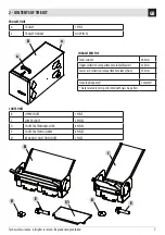
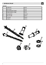
Page 7: ...ERISTICS Total volume 58 litres Upper collection compartment volume brazier 33 litres Lower ash collection compartment volume flue 25 litres Cleaning frequency 2 months Data related to tests performed with class A2 pellets CHUTE UNIT B UPPER CHUTE 1 PIECE C LOWER CHUTE 2 PIECES D CHUTE FASTENINGWASHER 8 PIECES E CHUTE FASTENING SCREW 8 PIECES S1 REAR ASH COLLECTION CHUTE 1 PIECE ...

Page 8: ...HE KIT GB AUGER UNIT F UPPER AUGER 1 PIECE G LOWER AUGER 1 PIECE H LOWER AUGER RIGHT CYLINDER 1 PIECE I UPPER AUGER RIGHT CYLINDER 1 PIECE M M5 FLANGED NUT 12 PIECES N M5 10TE SCREW 6 PIECES 0 CAP GASKET 6 PIECES 0D AUGER DISC 2 PIECES ...

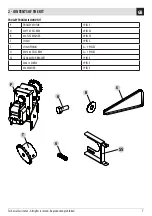
Page 9: ...s reserved Reproduction prohibited TROLLEYTRANSMISSION UNIT P TROLLEY MOTOR 1 PIECE Q M6 16TE SCREW 2 PIECES R M6 FLATWASHER 2 PIECES S CHAIN 1 PIECE T CHAIN PINION 2 1 PIECES U M6 20 STEI SCREW 2 1 PIECES SS GEAR MOTOR BRACKET 1 PIECE M6X12 SCREW 1 PIECE M6WASHER 1 PIECE ...

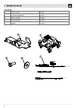
Page 10: ... TROLLEY PRESSOSTATO ARIA MOTORE TROLLEY V Z X K J 8 2 CONTENTS OFTHE KIT GB ELECTRIC UNIT V TROLLEY MICRO 1 PIECE Z ADDITIONAL MINI BOARD 1 PIECE X M6 16TE SCREW 2 PIECES K M6 FLATWASHER 2 PIECES J WIRING 1 PIECE ...

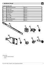
Page 11: ...LEY COMPLETING UNIT W PERFORMA SIDE CROSSPIECE 2 PIECES Y AUGER GASKET 2 PIECES A1 AUGER GASKET PLATE 2 PIECES A2 CLOSING BRACKET 2 PIECES A3 M5WASHER 2 PIECES A4 4 2 16 SCREW 8 PIECES A5 M4 25 SCREW 2 PIECES A6 BUMPER RUBBERWASHER 2 PIECES A7 SILICONE BUMPER 2 PIECES Other materials material for product packaging manual ...

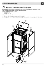
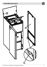
Page 12: ...the right of the structure In any case for safety and to work well remove both sides of the Performa boiler To remove the right panel D proceed as follows lift the tank cover C lift the front cover B open the decorative door A remove the two top screws x that secure the panel D to the boiler lift the panel D and let the joints k come out of the holes y on the structure of the boiler see image on t...

Page 13: ...k D 11 3 DISASSEMBLING BOILER SIDES GB Technical Assistance All rights reserved Reproduction prohibited ...

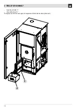
Page 14: ...e the two parts by removing the three screws t and proceed as described in the instructions on the following pages Trolley A is an accessory used to prolong the cleaning intervals of the boiler This type of cleaning and emptying of the boiler allows the ashes to be emptied after about three months instead of every week as per the standard version To better adapt to the spaces and requirements trol...

Page 15: ...chnical Assistance All rights reserved Reproduction prohibited Let s assume the trolley is to be installed to the right of the boiler The operations to be done are take the crosspiece W and secure it to the boiler using the four A4 screws GB ...

Page 16: ...2 1 14 4 TROLLEY KIT ASSEMBLY GB Open the ash holder 1 remove the ash pan 2 Thoroughly clean the lower and upper ash compartment if the boiler has already been used ...

Page 17: ... 3 on the structure two on the right side two on the left side and 2 on the inside Attention The supplied gaskets O have a knockout to be able to remove the central part based on the position in whichtheyareassembled Ontheinnerpart intheleftashpanpositioninthefigure assemblethering OD andgasket O andsecureeverythingwithscrews N ...

Page 18: ...OD O 16 4 TROLLEY KIT ASSEMBLY GB Do the same also for the right inner side assembled the ring OD gasket O and secure everything with the three N screws ...

Page 19: ...ction prohibited Positiontheashcompartmentchute B intheupperpartandsecureittothestructureusingthefourscrews E andthefourwashers D Attention Thepartofthepipethatprotrudes s fromthechute B mustbepositionedtowardsthetrolley inthe imagetotheright s The image below shows the chute B assembled ...

Page 20: ... Insert the gasket O on the upper auger F and insert all of it from the side opposite the position chosen for the trolley in this case to the left of the boiler Secure the upper auger assembly to the boiler structure with the three nuts M ...

Page 21: ... right trolley insertion side on the upper auger Secure the cylinder I to the structure using the three nuts M After having installed the auger and inserted the cylinder loosen the screw F3 and bring the element F2 to the end stop on the end part of the cylinder Make sure the auger turns Attention Afterhavinginstalledtheaugerononesideandthecylinderontheother makesuretheaxisturnsfreely ...

Page 22: ...Y Takeonechute C andinsertittotheleftoftheboiler positionedwiththechutelengthwisetowardstheinsideoftheboiler asshownin the image below Secure it to the structure using the two screws E and the two washers D The image below shows the left chute C in position ...

Page 23: ...ights reserved Reproduction prohibited Then insert the other chute C to the right of the boiler again with the chute lengthwise towards the inside Secure the chute C to the structure using the washer D and screw E The image below shows the right chute C in position ...

Page 24: ...T ASSEMBLY GB REAR ASH COLLECTION CHUTE ASSEMBLY Positionthechute S1 betweenthetwolowerchutes C totherightandtotheleftofthechuteS1 andattachittothechutesbymeans of the feather keys x Push the chute S1 flush on the lower auger unit ...

Page 25: ...l rights reserved Reproduction prohibited LOWER AUGER ASSEMBLY Take the lower auger G and insert it into the hole on the bottom left of the boiler Before inserting the auger G insert the gasket O Secure the auger G to the boiler structure using the three nuts M ...

Page 26: ... the corresponding gasket O and secure it with the three nuts M After having installed the auger and inserted the cylinder loosen the screw F3 and bring the element F2 to the end stop on the end part of the cylinder Make sure the auger turns Attention Afterhavinginstalledtheaugerononesideandthecylinderontheother makesuretheaxisturnsfreely ...

Page 27: ... KIT ASSEMBLY GB Technical Assistance All rights reserved Reproduction prohibited On the right part of the boiler near cylinders H and I insert the plate A1 and gasket Y and secure everything to the structure with the screw A5 ...

Page 28: ...ends of augers G and F and secure them with the screws U to the left of the boilers Atthispoint takethegearmotor P andassembleit inserting the pinion T Secure the pinion T with the screw U Before inserting the chain S fasten the support bracket SS of the gear motor P as in image using the supplied screw ...

Page 29: ... be secured to the boiler Secureitwiththetwowashers R andtwoscrews Q adjusting the position so that the chain has the right tension then secure it To make it easier to secure the gear motor P to the structure it is possible to remove the expansion vessel lock and move it Attention For proper chain tensioning its inclined side must notbetaut butslightlyloose Attention Adjust the P gear motor positi...

Page 30: ...OLLEY KIT ASSEMBLY GB TROLLEY PRESENCE MICRO ASSEMBLY Take the micro V and secure it to the lower right side trolley side using the two washers K and the two screws X Attention Makesurethetrolleykeepsthemicropressed ...

Page 31: ...d TROLLEY FRONT BRACKET Takethebracket A2 andinsertit ontherightsideofthetrolley onthelowerpartandsecureitwiththetwoscrews A4 Insertabumper rubber washer A7 at the top of the plate A2 TROLLEY REAR BRACKET Insert the other bracket A2 on the back part of the boiler and secure it with the screws A4 and the washers A3 ...

Page 32: ...A6 A6 30 4 TROLLEY KIT ASSEMBLY GB Take the two rubber washers A6 and insert them in the holes of the structure again on the trolley side ...

Page 33: ...es supplied Based on where it is positioned the two front or rear doors on the trolley must be opened or closed In our case assembling the trolley to the right the two doors 6 must be opened and blocked with the wing nuts 7 while the two rear doors 4 must be closed and blocked with the screw 5 Attention Werecommendsealingthetwounuseddoorswithblacksilicone suitedtowithstandhightemperatures upto300 ...

Page 34: ...Z in the top right near the boiler electronic board and make the electrical connections After having made all the electrical connections hook the trolley to the structure with the two lever closures Reassemble the sides Attention Makesurethetrolleykeepsthemicropressed ...

Page 35: ...on prohibited ELECTRICAL CONNECTION GENERAL LAYOUT Take the part of the wiring a with two red wires one yellow green one brown one blue and two red and connect it to the corresponding terminal on the additional mini board Z Connect the other end with the male connector C1 connected to the yellow green blue brown wires to the connector C2 coming from the boiler electronic board ...

Page 36: ...thertwoends h comingfromthewiring redwire mustbeconnectedtothegearmotor P Theimagebelowshowstheconnection to the gear motor P Take the other wiring with shorter wires and connect the end b to the mini board Z and the other c to the boiler board ...

Page 37: ...d connect the two female ends f to the trolley micro V The other end with the male female ends must be connected to the air pressure switch Disconnect the cable g already connected to the pressure switch and connect it to the male end d of the wiring connect the female end e to the pressure switch in the position of the previous cable g ...

Page 38: ...rs closethetwocaps 6 nearthefeedscrewinsertionhole toavoidloosingashduringtransport Thefrontorrearcapsdependingon whether the trolley is located to the right or left of the boiler open the trolley cover with the two levers check the level of the pellets If the level of ash is more than 50 empty the container Inanycase checktheleveloftheashdepositedinthetrolleyevery30days The frequency with which t...

Page 39: ......

Page 40: ...Via La Croce n 8 33074Vigonovo di Fontanafredda PN ITALY Telephone 0434 599599 a s Fax 0434 599598 Internet www mcz it e mail info red mcz it 8901628400 REV 6 24 01 2019 ...

Reviews: