background image

FPI FIREPLACE PRODUCTS INTERNATIONAL LTD.  6988 Venture St., Delta, BC  Canada, V4G 1H4

919-914

MODELS: U39-NG11 Natural Gas    U39-LP11 Propane 

04.24.19

Ultimate™ U39 Freestanding Gas Stove

Owners & 

     Installation Manual 


www.regency-fire.com


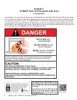
-  Do not store or use gasoline or other flammable vapors and liquids in the vicinity of this or any other 

appliance. 

- WHAT TO DO IF YOU SMELL GAS
 • 

Do not try to light any appliance.


•  Do not touch any electrical switch: do not use any phone in your building.


  Leave the building immediately.


•  Immediately call your gas supplier from a neighbour's phone. Follow the gas supplier's  

instructions.


• If you cannot reach your gas supplier, call the fire department.


  Installation and service must be performed by a qualified installer, service agency or the gas supplier.

     WARNING
FIRE OR EXPLOSION HAZARD
Failure to follow safety warnings exactly could result in serious
injury, death, or property damage. 

Installer

: Please complete the details on the back cover 

and leave this manual with the homeowner.

Homeowner:

 Please keep these instructions for future reference.

Tested by: 

Certified to/Certifié pour: CSA 2.17-2017
                                            ANSI Z21.88-2017
                                            CSA 2.33-2017

Summary of Contents for U39-LP11

Page 1: ...ding Leave the building immediately Immediately call your gas supplier from a neighbour s phone Follow the gas supplier s instructions If you cannot reach your gas supplier call the fire department Installation and service must be performed by a qualified installer service agency or the gas supplier WARNING FIRE OR EXPLOSION HAZARD Failure to follow safety warnings exactly could result in serious ...

Page 2: ...arnock Hersey Intertek for both safety and efficiency As it also bears our own mark it promises to provide you with economy comfort and security for many trouble free years to follow Please take a moment now to acquaint yourself with these instructions and the many features of your ULTIMATE Direct Vent Freestanding Gas Stove U38 39 Video This appliance may only be installed in an after marketperma...

Page 3: ... Terminations 21 Cathedral Ceilings 22 Converting a Class A Metal Chimney to a Direct Vent System 23 System Data 24 Gas Connection 24 High Elevation 24 Conversion from NG to LP 25 Conversion to Lower BTU Rating 26 Gas Pipe Pressure Testing 26 SIT 829 Valve Description 27 Aeration Adjustment 27 On Demand Pilot LIght 27 Log Set Installation 28 Log Set Installation 31 Wiring Diagrams 34 Optional Wall...

Page 4: ...U39 11 ULTIMATE Freestanding Gas Stove dimensions ALL PICTURES DIAGRAMS SHOWN THROUGHOUT THIS MANUAL ARE FOR ILLUSTRATION PURPOSES ONLY ACTUAL PRODUCT MAY VARY DUE TO PRODUCT ENHANCEMENTS 913 16 250mm 108mm 4 1 4 ...

Page 5: ...AS FIREPLACE HEATER NOT FOR USE WITH SOLID FUELS FOYER AU GAZ À ÉVACUATION NE PAS UTILISER AVEC UN COMBUSTIBLE SOLIDE Made in Canada Fabriqué au Canada Listed VENTED GAS FIREPLACE HEATER FOYER AU GAZ À ÉVACUATION Certified to Certifié C 4001172 For Use Only with Barrier Part 732 929 Follow installation instructions Utiliser uniquement avec l écran de sécurité n 732 929 Suivre les consignes d install...

Page 6: ...directly in line with the exhaust vent terminal for the horizontally vented gas fueled heating appliance or equipment The sign shall read in print size no less than one half 1 2 inch in size GAS VENT DIRECTLY BELOW KEEP CLEAR OF ALL OBSTRUCTIONS 4 INSPECTION The state or local gas inspector of the side wall horizontally vented gas fueled equipment shall not approve the installation unless upon ins...

Page 7: ...BE KEPT CLEAN DUE TO HIGH TEMPERATURES THE APPLIANCE SHOULD BE LOCATED OUT OF TRAFFIC AND AWAY FROM FURNITURE AND DRAPERIES WARNING FAILURE TO INSTALL THIS APPLIANCE CORRECTLY WILL VOID YOUR WARRANTY AND MAY CAUSE A SERIOUS HOUSE FIRE YOUNG CHILDREN SHOULD BE CARE FULLY SUPERVISED WHENTHEY ARE IN THE SAME AREA AS THE APPLI ANCE TODDLERS YOUNG CHILDREN AND OTHERS MAY BE SUSCEPTIBLE TO ACCIDENTAL CO...

Page 8: ...or servicing proper operation and around the air openings into the combustion chamber 2 The appliance may be installed on a flat solid continuoussurface e g wood metal concrete This may be the floor or it can be raised up on a platform to enhance its visual impact The appliance may be installed on carpeting tile wood flooring or other combustible material because the appliance s metal pedestal bas...

Page 9: ...pliance must be connected to the specifiedventandterminationcaptotheoutside of the building envelope Never vent to another room or inside a building Make sure that the vent is fitted as per the instructions starting in Locating Your Ultimate Gas Stove section 6 Inspecttheventingsystemannuallyforblockage and any signs of deterioration 7 Venting terminals shall not be recessed into a wall or siding ...

Page 10: ...e the balanced flue technology Co Axial system The inner liner vents products of combustion to the outside while the outer pipe draws outside combustion air into the combustion chambertherebyeliminatingtheneedtouseheated room air for combustion and losing warm room air up the chimney Note These flue pipes must not be connected to any other appliance The gas appliance and vent system must be vented...

Page 11: ...tended above meter regulator assembly 36 90cm a J Clearance to service regulator vent outlet 36 90cm K Clearance to non mechanical air supply inlet to building or the combustion air inlet to any other appliance 12 30cm 9 23cm L Clearance to a mechanical air supply inlet 3 91cm above if within 10 3m horizontally 72 1 8m 36 90cm b M Clearance above paved sidewalk or a paved driveway located on publi...

Page 12: ...Length 7 Galvanized N A N A 4D7A N A N A N A N A Adjustable Length 7 Black N A N A 4D7AB N A N A N A N A Extension Pipe 8 1 2 Galvanized 46DVA 08A N A N A N A N A N A N A Extension Pipe 8 1 2 Black 46DVA 08AB N A N A N A N A N A N A Adjustable Length 12 Galvanized N A N A 4D12A N A SV4LA12 TC 4dLSI N A Adjustable Length 12 Black N A N A 4D12A N A SV4LBA12 TC 4dLSIB N A Extension Pipe 16 Galvanized...

Page 13: ...HKA 4DHTK2 4DHTKA SV SHK TM4 HTK VDV KW04 Horizontal Termination Kit B 46DVA KHA Changed Components 4DT HKB 4DHTK1 4DHTKB SV HK TM4 HTK VDV K04 Vertical Termination Kit Disc 4DT VKC 4DHTK 4DHTK SV FK N A N A FPI 946 506 P Vent Guard Optional for AstroCap 946 205 Vinyl Siding Shield for Riser Vent Terminal 510 994 Rigid Pipe Adaptor Must use with all rigid piping 946 208 P Vent Guard Optional for R...

Page 14: ...onents WARNING Do not combine venting components from different venting systems However use of the the AstroCapTM and FPI Riser is acceptable with all systems When using Rigid Vent other than Simpson Dura Vent 3 screws must be used to secure rigid pipe to adaptor The FPI AstroCapTM and FPI Riser Vent terminal are certified for installations using FPI venting systems as well as Simpson Dura Vent Di...

Page 15: ...nt gas appliance must use its own separate vent system Common vent systems are prohibited SAFETY PRECAUTIONS FOR THE INSTALLER 1 Wear gloves and safety glasses for protection 2 Exercise extreme caution when using ladders or on roof tops 3 Be aware of electrical wiring locations in walls and ceilings RIGID PIPE VENTING ARRANGEMENTS Vertical Termination Systems for Residential Manufactured and Mobil...

Page 16: ...between 90o elbows is required Lengthsdonotincludeelbowindicated Vent restrictor position A fully open Refer to the Venting Ar rangement section One 90o elbow Two 45o elbows Option V H V1 V V1 A 1 Min 1 Max 1 Min 2 Min B 1 Min 2 Max 2 Min 3 Min C 2 Min 3 Max 2 Min 4 Min D 2 Min 4 Max 2 Min 4 Min With these options max total pipe length is 30 feet with min of 4 feet total vertical and max 4 feet to...

Page 17: ...ndclearancedimensions in ExteriorVentTermination Locations to DV Stove Horizontal Vent Kit sections 1 Set the unit in its desired location Check to determine if wall studs will be in the way of the venting system adjust location until all clearances are met and there are no obstructions Note A 1 1 2 38mm clearance around the outer pipe must be maintained except thatonlya1 25mm clearanceisneeded at...

Page 18: ...sealing with Mill Pac and securing with 3 of the 8 x 1 2 black screws Pipe seams should be facing the wall 16 Attach the 90o elbow onto the pipe section by sealing with Mill Pac and securing with 3 of the 8 x 1 2 screws black 17 Slide the adjustable pipe section onto the 90o elbow Theflexmayhavetobecompressedback in order for the adjustable pipe to properly mate to the elbow Seal with Mill Pac and...

Page 19: ...nit flue outlet to the ceiling the ceiling thickness the vertical rise in an attic or second storey and allowforsufficientverticalheightabovetheroofline Formulti storeyapplications firestopsarerequired at each floor level If an offset is needed additional pipe elbows and supports will be required DURA VENT VENTING COMPONENTS You will require the following components with your new Regency Direct Ve...

Page 20: ...the vent will be terminated If the wall being penetrated is constructed of non combustible material i e masonry block or concrete a 7 diameter hole is acceptable Diagram 3 DURA VENT HORIZONTAL TERMINATIONS 1 Set the unit in its desired location Check to determine if wall studs or roof rafters are in the way when the venting system is attached If this is the case you may want to adjust the location...

Page 21: ...ed by the decorative wall thimble cover See diagram 6 4 If installing the vent termination to a wall with vinyl siding the Vinyl Siding Standoff must be used Attach the Vinyl Siding Standoff to the HorizontalVentTermination butfirstrunabead of non hardening mastic around its outside edges so as to make a seal between vent cap andthestandoff InstalltheVinylSidingStandoff between the vent cap and th...

Page 22: ...utilized in the attic as well as above the roofline The galvanized finish is desirable above the roofline due to its higher corrosion resistance Continue to add pipe sections through the flashing until the height of the vent cap meets the minimum height requirements specified in diagram 12 or local codes Note that for steep roof pitches the vertical height must be increased A poor draft or down dr...

Page 23: ...extension joins the support CONVERTING A CLASS A METAL CHIMNEY TO A DIRECT VENT SYSTEM General There are two different types of direct vent Prior to installation and connection of the vent system to a factory built chimney the chimney must be inspected and thoroughly cleaned by a qualified service person such as a certified chimney sweep or home inspection service The direct vent system must not b...

Page 24: ... 730 920 For Natural Gas installations above 4500 ft follow current CAN CGA B149 1 In U S A for installations above 2000 ft refer to current ANSI Z223 1 Sc8 8 1 2a appendix F for resizing orifice System Data U39 11 Altitude for 0 to 2000 feet Burner Inlet Orifice Sizes Natural Gas Propane Burner 36 51 Max Input Natural Gas 33 500Btu hr Propane 32 500Btu hr Min Input Natural Gas 23 500Btu hr Propan...

Page 25: ...ce with the allen key and replace with the LPG pilot orifice in the kit 11 Reinstall new burner orifice LPG stamped 51 and tighten 13 Check for gas leaks with a proper soapy solution or leak detector 14 Check for proper spark between the ignitor and pilot cap Refer to Lighting Procedure section of the manual for lighting sequence 15 Check pilot flames Correct flame pat tern has 3 strong blue flame...

Page 26: ...r turn off the gas valve disconnect the hose and tighten the screw clockwise with a 1 8 flat screwdriver Note Screw should be snug but do not over tighten Natural Gas Conversion Kit 730 920 Contains Qty Part Description 1 904 240 Burner Orifice 37 NG 1 918 034 Decal Converted to 31 000 Btu 1 918 033 Instruction Sheet Propane Conversion Kit 730 922 Contains Qty Part Description 1 904 390 Burner Ori...

Page 27: ...en key to turn the turning gear which will adjust the air shutter Open the air shutter for a blue flame or close it for a yellow flame Note Any damage due to carboning resulting from improperly setting the aeration controls is NOT covered under warranty Note Aeration Adjustment should only be performed by an authorized Regency Installer at the time of installation or service Clockwise to open coun...

Page 28: ...upport A B 3 Place the Middle Left Log B on the two pins as shown The gas log kit contains the following a 02 65 Rear Log b 02 56 Middle Left Log c 02 44 Front Left Log d 02 46 Left Top Log e 02 45 Front Right Log f 02 47 Center Log g 02 48 Middle Right Log C 4 Place Front Left Log C onto the 2 front pins as shown Cutout Pin D B A 5 Place the Left Top Log D on the pin on Log B and on top of the cu...

Page 29: ...burner tray E Bracket The bottom right edge of Log G must sit snugly against the bracket Side View G 9 TaketheEmbaglow steelwoollikematerial lightlyseparate it and set a small amount over the visible burner ports in front and between the front left log and the log under the Y log indicated in the picture IMPORTANT DO NOT compress this material down on the burner ports Embaglow 10 Next take the whi...

Page 30: ... burner to the other If there is any flame hesitation check that area for any blockage of the burner port F 0 2 4 7 E 02 45 A 02 65 G 02 48 D 0 2 4 6 B 02 56 C 02 44 11 Using the harder coal like embers carefully spread these around the OUTSIDE of the burner 1 cup on each side Do not place or use these hard material embers on top of the burner Coal Embers outside burner only ...

Page 31: ...ddle Left Log B on the two pins as shown The driftwood log kit contains the following A Rear Log B Middle Left Log C Front Left Log D Left Top Log E Front Right Log F Center Log G Middle Right Log C 4 Place Front Left Log C onto the 2 front pins as shown Cutout Pin D B A 5 Place the Left Top Log D on the pin on Log B and on top of the cut out on Log A C 1 Carefully remove the logs from the box and...

Page 32: ...r tray E Bracket The bottom right edge of Log G must sit snugly against the bracket Side View G 9 TaketheEmbaglow steelwoollikematerial lightlyseparate it and set a small amount over the visible burner ports in front and between the front left log and the log under the Y log indicated in the picture IMPORTANT DO NOT compress this material down on the burner ports Embaglow 10 Next take the white Pl...

Page 33: ...lows smoothly from one end of burner to the other If there is any flame hesitation check that area for any burner port blockage 11 Using the harder coal like embers carefully spread these around the OUTSIDE of the burner 1 cup on each side Do not place or use these hard material embers on top of the burner Coal Embers outside burner only ...

Page 34: ...g power to the receptacle box provided with the unit in case the fan is installed at a later date Caution Ensure that the wires do not touch any hot surfaces and are away from sharp edges CAUTION Labelallwires prior to disconnection when servicing controls Wiring errors can cause improper and dangerous operation ENGLISH REMOTE TP TH TPTH MOTOR RECEIVER FCM COM Green White Red Black Ground Green Ne...

Page 35: ... adjusting the primary air to ensure that the flame does not carbon First allow the unit to burn for 15 min to stabilize 3 Check for proper draft CAUTION Any alteration to the product that causes sooting or carboning that results in damage to the exterior facia is not the responsibility of the manufacturer Recommended Maximum Lead Length Two Wire When Using Wall Thermostat CP 2 System Wire Size Ma...

Page 36: ...y difficult to remove Use a non abrasive cleaner and NEVER clean the glass while it is hot Proflame video DO NOT BURN THE APPLIANCE WITHOUT THE GLASS FRONT IN PLACE NOTE This appliance will operate during power outages Onlythefanwillnotoperateuntilpower is restored If the remote batteries in both the handheldtransmitterorreceiverlosepower the appliance can still be operated by sliding the switch o...

Page 37: ...intenance can cause injury or property damage Refer to the owner s information manual provided with this appliance For assistance or additional information consult a qualified installer service agency or gas supplier AVERTISSEMENT Quiconque ne respecte pas à la lettre les instructions dans la présente notice risquede déclencher un incendie ou une explosion entraînant des dommages des blessures ou ...

Page 38: ...hin the unit these sounds will likely re occur Again this is normal for steel fireboxes Blower Thermodisc When this thermally activated switch turns ON it will create a small clicking sound This is the switch contacts closing and is normal Pilot Flame While the pilot flame is on it can make a very slight whisper sound Gas Control Valve As the gas control valve turns ON and OFF a dull clicking soun...

Page 39: ... PROFLAME Transmitter Blue LCD display UP DOWN Arrow Key ON OFF Key THERMOSTAT Key MODE Key Low battery alarm Child safety lock out Room Temperature Aux ON Set Point Temperature Level State Flame ON Thermostat OFF ON SMART Fan Fig 2 Transmitter LCD display Transmission Figure 2 Transmitter LCD Display Figure 1 Proflame Transmitter OPERATING PROCEDURE Initializing the System for the first time Inst...

Page 40: ...til the desired set temperature is dis played on the LCD screen of the Transmitter Remote Flame Control The Proflame GTMF has six 6 flame levels With the system on and the flame level at the maximum in the appliance pressing the Down Arrow Key once will reduce the flame height by one step until the flame is turned off The Up Arrow Key will increase the flame height each time it is pressed If the U...

Page 41: ...operation Toactivatethisfunction presstheMODEandUPKeysatthesametime fig 18 To de activate this function press the MODE and UP Keys at the same time LOW BATTERY POWER DETECTION Transmitter The life span of the remote control batteries depends on various factors quality of the batteries used the number of ignitions of the appliance the number of changes to the room thermostat set point etc When theT...

Page 42: ...is condensation and fog is normal and will disappear in a few minutes as the glass heats up Never operate the appliance without the glass properly secured in place or with the door open 8 Periodically check the pilot flames Correct flame pattern has three strong blue flames 1 flowing around the thermopile and 1 around the thermocouple and 1 flowing across the rear of the burner it does not have to...

Page 43: ...anty DOOR GASKET If the door gasket requires replacement use 7 8 diameter oval door gasket Part 732 570 LATCH ADJUSTMENT The door latch may require adjustment as the door gasket material compresses after a few fires and after glass replacement Turn the adjustable catch to tighten or loosen the latch GLASS REPLACEMENT Your ULTIMATE stove is supplied with high temperature 5 mm Neoceram ceramic glass...

Page 44: ...ve the grounding prong from this plug To Remove U39 Fan from front of Unit 1 Unplug or disconnect power source to stove 2 Remove all logs and the rear log support then remove the 10 screws holding the access panel in place 3 Unclip the black and white wires from the fan motor 4 Open both side doors and gently pull the flex pipe away from the center otherwise the fan can catch on the flex pipe duri...

Page 45: ...may want to put a soft cloth on the base of the unit so that when the pedestal door is open it doesn t scratch the paint 2 Remove 2 screws to remove receiver cover 3 Remove chain from door and unit remove 4 screws holding the access panel in place 11 Remove all 18 screws holding the burner tray assembly in place 12 Carefully lift the valve tray assembly out 13 Remove the valve tray and replace 14 ...

Page 46: ...560 922 Louver Assy Black 9 732 513 Relief Door Assembly 10 732 022 Mounting Plate Gasket 11 730 517 P Fan Assembly 910 331 P Fan Motor 120 Volt 12 910 813 Power Cord 120 Volt 15 Pedestal Assembly 16 730 039 Pedestal Door 17 904 257 Pedestal Door Magnet 18 732 084 Pedestal Back 20 730 531 Short Side Panel Door Assy 21 560 031 Hinge for Side Panel 23 904 258 Side Panel Door Magnet 24 948 255 Door L...

Page 47: ... 008 Gasket Burner Tray Firebox 78 737 550 Burner Assembly NG LP 80 260 565 Air Shutter Gear Assembly Female 81 904 565 Hex Key 3 16 AF 82 630 009 Gasket Burner Tray Air Passage 84 Air Shutter Gear Assembly Male 85 910 581 Stepper Motor NG 85 910 582 Stepper Motor LP 911 228 P Remote Receiver 910 592 Remote handheld GTMF 911 127 Battery Compartment Door 910 036 Pilot Orifice NG 910 037 Pilot Orifi...

Page 48: ...escription 209 732 943 Black Wrap Door Complete 732 944 Brushed Nickel Wrap Door Complete 101 732 570 Door Gasket Kit 105 Ceramic Paper 107 936 243 Glass Gasket 111 Door Frame Fibre Paper 208 940 325 P Wrap Glass 209 732 020 Door Mounting Bracket Not available as a replacement part ...

Page 49: ...Regency U39 11 ULTIMATE Freestanding Gas Stove 49 notes ...

Page 50: ...Control Boards Wiring Switches Blowers Blower Control Module Battery Pack Remote Control Systems 2 Enamel Panels 1 Venting Venting Components 1 All Stainless steel surrounds 1 All Firebox Media Crystals Firebeads Volcanic Ceramic Spa Stones 1 All hardware 1 Mesh Glass Safety Barriers 1 Accent Light Bulbs 1 Glass Crazing 1 Conditions Warranty protects against defect in manufacture or FPI factory as...

Page 51: ...drafts installation error installation by an unqualified installer incorrect chimney components including but not limited to cap size or type operator error abuse misuse use of improper fuels lack of regular maintenance and upkeep acts of God weather related problems from hurricanes tornados earthquakes floods lightning strikes bolts or acts of terrorism or war which result in malfunction of the a...

Page 52: ...e the U S should consult their local provincial or national legal codes for additional terms which may be applicable to this warranty How to Obtain Warranty Service Customers should contact the authorized selling dealer to obtain warranty service In the event the authorized selling dealer is unable to provide warranty service please contact FPI by mail at the address listed below Please include a ...

Page 53: ...elow in order for us to serve you better Warranty Registration Form or Register online immediately at the above Web Site Warranty Details Serial Number required Purchase Date required mm dd yyyy Product Details Product Model required Dealer Details Dealer Name required Dealer Address Dealer Phone Installer Date Installed mm dd yyyy Your Contact Details required Name Address Phone Email For purchas...

Page 54: ......

Page 55: ......

Page 56: ...mation Dealer Name Address _______________________________________________ ___________________________________________________________________ Installer ____________________________________________________________ Phone ____________________________________________________________ Date Installed _______________________________________________________ Serial No ______________________________________...

Reviews: