background image

FPI FIREPLACE PRODUCTS INTERNATIONAL LTD.  6988 Venture St., Delta, BC  Canada, V4G 1H4

WARNING:  
If the information in these instructions are not followed ex-
actly, a fi re or explosion may result causing property damage, 
personal injury or loss of life. 

FOR YOUR SAFETY
Do not store or use gasoline or other fl ammable vapors and 
liquids in the vicinity of this or any other appliance.

Installation and service must be performed by a qualifi ed 
installer, service agency or the gas supplier.

FOR YOUR SAFETY
What to do if you smell gas:

Do not try to light any appliance

Do not touch any electrical switch: 
do not use any phone in your build-
ing.

Immediately call your gas supplier 
from a neighbour's phone. Follow 
the gas supplier's instructions.

If you  cannot reach your gas sup-
plier, call the fi re department.

918-530a

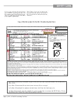
MODELS: U38-NG1 Natural Gas    U38-LP1 Propane 

04/05/11

ULTIMATE U38 Freestanding Gas Stove

Owners & 

Installation Manual

Tested by:

Installer: Please complete the details on the back cover 

and leave this manual with the homeowner.

Homeowner: Please keep these instructions for future reference.

www.regency-fi re.com

Summary of Contents for ULTIMATE U38

Page 1: ...ency or the gas supplier FOR YOUR SAFETY What to do if you smell gas Do not try to light any appliance Do not touch any electrical switch do not use any phone in your build ing Immediately call your gas supplier from a neighbour s phone Follow the gas supplier s instructions If you cannot reach your gas sup plier call the fire department 918 530a MODELS U38 NG1 Natural Gas U38 LP1 Propane 04 05 11...

Page 2: ...ed to provide you with all the warmth and charm of a woodstove at the flick of a switch The models U38 NG1 and U38 LP1 of this series has been approved by Warnock Hersey for both safety and efficiency As it also bears our own mark it promises to provide you with economy comfort and security for many trouble free years to follow Please take a moment now to acquaint yourself with these instructions ...

Page 3: ...26 Fan Maintenance 27 Removing Valve 28 PARTS LIST U38 1 Main Assembly 29 U38 1 Burner Log Assembly 30 U38 1 Door Assemblies 31 WARRANTY Warranty 35 SAFETY LABEL Copy of Safety Label 5 REQUIREMENTS MA Code CO Detector 6 INSTALLATION Before You Start 7 Important Message 8 General Safety Information 8 Installation Checklist 8 Clearances to Combustibles 9 Optional Outside Air 9 Draft Hood 10 High Ele...

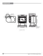
Page 4: ...4 Regency U38 1 ULTIMATE Freestanding Gas Stove DIMENSIONS U38 NG1 U38 LP1 ...

Page 5: ...ules de camping ou la norme 24 CFR Part 3280 Manufactured Home Construc tion and Safety Standard Si ces normes ne sont pas pertinentes utilisez la norme ANSI NCSBCS A225 1 NFPA 501A Manufactured Home Installations Standard ou ANSI A119 2 ou NFPA 501C Standard for Recreational Vehicles Cet appareil doit être utilize uniquement avec le type de gaz indiqué sur la plaque signalétique Cet appareil peut...

Page 6: ...directly in line with the exhaust vent terminal for the horizontally vented gas fueled heating appliance or equipment The sign shall read in print size no less than one half 1 2 inch in size GAS VENT DIRECTLY BELOW KEEP CLEAR OF ALL OBSTRUCTIONS 4 INSPECTION The state or local gas inspector of the side wall horizontally vented gas fueled equipment shall not approve the installation unless upon ins...

Page 7: ...ERVICE PERSON MORE FREQUENT CLEANING MAY BE REQUIRED DUE TO EXCESSIVE LINT FROM CARPETING BEDDING MATERIAL ETC ITISIMPERATIVETHAT CONTROLCOMPARTMENTS BURNERS ANDCIRCULATINGAIRPASSAGEWAYS OF THE APPLIANCE BE KEPT CLEAN DUE TO HIGH TEMPERATURES THE APPLIANCE SHOULD BE LOCATED OUT OF TRAFFIC AND AWAY FROM FURNITURE AND DRAPERIES WARNING FAILURE TO INSTALL THIS APPLIANCE CORRECTLY WILL VOID YOUR WARRA...

Page 8: ...hecked annually 14 Do not strike the glass door 15 Under no circumstances should any solid fuels wood paper cardboard coal etc be used in this appliance 16 The appliance area must be kept clear and free of combustible materials gases and other flam mable vapours and liquids 17 Donotconnectthisgasappliancetochimneyflue serving a separate sold fuel burning appliance 18 WARNING Operationofthisapplian...

Page 9: ...BUSTIBLES The clearances listed below are MINIMUM dis tances Measure the clearance to both the appli ance and the chimney connector The farthest distance is correct if the two clearances do not coincide For example if the appliance is set as indicated in one of the figures but the connector is tooclose movethestoveuntilthecorrectclearance to the connector is obtained This unit can be installed on ...

Page 10: ...r srequirementsand local building codes In cold climates we recom mendtheuseofinsulatedB vent chase andliners For altitudes above 2000 ft we recommend that a minimum flue height of 12 ft is used Flue Mounting Bracket Attach the flue mounting bracket with the enclosed screw as shown in the diagram DRAFT HOOD This heater has a draft hood built in It must not be altered obstructed or blocked in any w...

Page 11: ...d or OUT 6 pressure tap s turning counterclockwise with a 1 8 wide flat screwdriver 3 Attach manometer to IN and or OUT pressure tap s using a 5 16 ID hose GAS CONNECTION The gas line can be rigid pipe or to make instal lation easier use a listed flexible connector if allowed by local codes Copper may also be used if approved by local codes The gas connection at the valve is 3 8 NPT For minimum an...

Page 12: ...1 2 Type B Black Oxide 1 910 073 Spark Generator Battery Holder 1 910 074 Spark Generator Switch C W Wire 1 910 078 Battery Size AA Energizer En91 2 910 199 Clip Wire Holder 1 910 903 Wire Fan To Power Cord Ground 30 in 904 781 Velcro Hook Black 904 782 Velcro Hook Black Note Use a magnetic type screwdriver if possible 9 Remove the black protection cap by hand from the high low knob Fig 1 10 Inser...

Page 13: ...parker 1 Remove the back pedestal cover by unscrewing the 4 screws 2 Remove the front control panel by unscrewing the 6 screws 4 Plug up the Piezo Ignitor mounting hole with the plastic plug Fig 6 Burner Orifice 18 Remove burner orifice with a 1 2 wrench while using a 9 16 wrench to hold onto the elbow behind the orifice then discard the orifice WARNING Do not over tighten the screw Recommended to...

Page 14: ...the hole on the heat shield 18 We recommend mounting the DC Sparker box onto the pedestal back cover 19 Check for gas leaks 20 Check inlet and outlet pressures 21 Check operation of flame control 22 Check for proper flame appearance and glow on logs 6 Secure with screw 8 Attach one end of the green ground wire to the grounding stud on the inside of the pedestal 13 Apply the plastic bushing to the ...

Page 15: ...ctor setting at High 40 000 Btu h Vent Restrictor setting at Low 30 000 Btu h 4 Unscrew the 2 Rear Log Pins and move to the front hole position 5 Remove Rear Log Bracket and slide the Log Bracket Restrictor between the Rear Log Bracket and the burner secure with the 2 screws 7 Reinstall new burner orifice NG stamped 37 or LP stamped 52 and tighten 8 Reverse steps 3 and 2 9 Adjust Vent restrictor s...

Page 16: ...e two pins on the rear log support 4 Place the Middle Left Log B 02 56 on the two pins as shown Read the instructions below carefully and refer to the diagrams If logs are broken do not use the unit until they are replaced Broken logs can interfere with the pilot operation The gas log kit contains the following a 02 65 Rear Log b 02 56 Middle Left Log c 02 44 Front Left Log d 02 46 Left Top Log e ...

Page 17: ...ront Right Log E 02 45 on the two pins as shown 9 Place the lava rock in the area between the left and right logs leaving a space in the middle for log F 02 47 C 02 44 5 Sprinkle some lava rock just in front of B 02 56 on the burner holes Lava Rock B 02 56 6 Place Front Left Log C 02 44 onto the 2 front pins as shown 10 Separate platinum embers and place around the lava rock on the burner Avoid st...

Page 18: ... must sit snugly against the bracket Side View G 02 48 E 02 45 F 0 2 4 7 12 Position notch in Front Right Log G 02 48 on Log F 02 47 and push the bottom right edge against the bracket on the burner tray G 02 48 13 Test fire to ensure proper light off make sure flame flows smoothly from one end of burner to the other If there is any flame hesitation check that area for any blockage of the burner po...

Page 19: ... FRONT DOOR INSTALLATION packaged separately 1 Open the two side panels 4 The latches should already be at the proper setting If they are too hard or too easy to close you may want to adjust them by loosening the latch catch See diagram 3 Diagram 2 Diagram 3 5 Remove the blue plastic protective coating from the glass 6 Test the seal around the door by placing a piece of paper between the unit and ...

Page 20: ... from extreme heat is very important Run wires from the fireplace to that location use Thermostat Wire Table 2 Connect the wires as per the wiring diagram above CAUTION Do not connect the millivolt re mote control wires to the 120V wires 3 Install 3AAAalkaline batteries in transmitter and 4 AA alkaline batteries in the receiver Install the receiver and its cover in the wall Switch the remote recei...

Page 21: ...y is needed for the fan blower operation Caution Ensure that the wires do not touch any hot surfaces and are away from sharp edges WARNING Electrical Grounding Instructions This appliance is equipped with a three pronged grounding plug for your protec tion against shock hazard and should be plugged directly into a properly grounded three prong receptacle Do not cut or remove the grounding prong fr...

Page 22: ...ON Label all wires prior to disconnection whenservicingcontrols Wiringerrors can cause improper and dangerous operation For PROPANE Units and Units Equipped with DC Spark Boxes For installation of the DC Spark Box refer to the LP Conversion instructions in this manual ...

Page 23: ...losed to prevent possible shock 3 Check to ensure there are no gas leaks 4 Make sure the three pieces of door glass are properly positioned Never operate the appliance with any of the glass removed or with the door open 5 Verify that all venting and the cap is unob structed 6 Verify log placement If the pilot cannot be seen when lighting the unit the logs or the embers have been incorrectly positi...

Page 24: ...floor WHAT TO DO IF YOU SMELL GAS Do not try to light any appliance Do not touch any electric switch do not use any phone in your building Immediately call your gas supplier from a neighbors phone Follow the gas supplier s instructions If you cannot reach your gas supplier call the fire department C Us try to repair it call a qualified service technician Force or attempted repair may result in a f...

Page 25: ...as regulator or valve Unit Body Firebox Differenttypesandthicknessesofsteelwillexpand and contract at different rates resulting in some cracking and ticking sounds will be heard throughout the cycling process AERATION ADJUSTMENT The burner aeration is factory set but may need adjusting due to either the local gas supply or altitude U38 1 with 40 000 Btu h U38 NG1 Natural Gas 1 4 open U38 LP1 Propa...

Page 26: ...at the flow of combustion and ventilation air is not obstructed During the annual service call the burners should be removed from the burner tray and cleaned Replace the embers do not block the pilot or burner ports 5 Keep the area near the appliance clear and free from combustible materials gasoline and other flammable vapours and liquids 6 Verify proper operation after servicing LOG REPLACEMENT ...

Page 27: ...4 Remove the glass retainers sides top and bottom and the door catch plate 5 Replace the glass The glass must have gasketing around it 6 Reverse the previous steps replace the retainers and fasten with the nuts but do not overtighten as this can break the glass Note the door catch plate fits on top of the left side retainer 7 Put gasket glue on the retainers but do not put glue on the screws Repla...

Page 28: ...paint See diagram below 2 Undo the six screws holding the control panel in place 3 Disconnect all wires from the back of the panel and then remove panel You should lay the panel on a soft cloth so it doesn t get marked up See diagram below 5 Carefully remove the logs and lava rock 6 At this point you should disconnect the gas at the valve 7 Remove the burner by removing the two 1 4 hex head screws...

Page 29: ...vailable as a replacement part 1 560 920 Top Bottom Gold Louver Assy 560 921 Top Bottom Brush Nickel Assy 560 922 Top Bottom Black Louver Assy 9 560 055 Fan Access Door 10 730 034 Gasket for Fan Access Door 730 517 P Fan Assembly 11 910 331 P Fan Motor 120 Volt 12 910 794 Power Cord 120 Volt 15 Pedestal Assembly 16 730 039 Pedestal Door 17 904 257 Pedestal Door Magnet 18 560 025 Pedestal Back 19 7...

Page 30: ...ly Natural Gas 750 526 P Valve Assembly Propane 60 910 478 Valve S I T Natural Gas Propane 904 240 37 Orifice N G at 30 000 Btu hr 904 690 31 Orifice N G at 40 000 Btu hr 904 390 52 Orifice Propane at 30 000 Btu hr 904 641 50 Orifice Propane at 38 000 Btu hr 71 730 528 Rear Log Bracket Assy 72 910 034 Pilot Assy S I T 3 flame N G 910 035 Pilot Assy S I T 3 flame Propane 75 730 935 Log Set 78 730 5...

Page 31: ...730 932 Gold Wrap Door Complete 730 933 Black Wrap Door Complete 730 934 Brushed Nickel Wrap Door Complete 101 650 920 Door Gasket Kit 105 Ceramic Paper 107 936 243 Glass Gasket 111 Door Frame Fibre Paper 208 940 325 P Wrap Glass Not available as a replacement part Part Description ...

Page 32: ...32 Regency U38 1 ULTIMATE Freestanding Gas Stove NOTES ...

Page 33: ...Regency U38 1 ULTIMATE Freestanding Gas Stove 33 NOTES ...

Page 34: ...34 Regency U38 1 ULTIMATE Freestanding Gas Stove NOTES ...

Page 35: ...tor or agent Transportation Prepaid if requested It is the general practice of FPI to charge for larger higher priced replacement parts and issue credit once the replaced component has been returned to FPI and evalu ated for manufacturer defect The authorized selling dealer is responsible for all in field service work carried out on your Regency product FPI will not be liable for results or costs ...

Page 36: ..._____________________________________ Printed in Canada Regency fireplace products are designed with reliability and simplicity in mind In addition our internal Quality Assurance Team carefully inspects each unit thoroughly before it leaves our door Fireplace Products Internation al Ltd is pleased to extend this Limited Lifetime Warranty to the original purchaser of a Regency Product See the insid...

Reviews: