background image

INSTRUCTION MANUAL

BARRACUDA

 200

ZW

PORTABLE WALKING FOOT SEWING MACHINE

Summary of Contents for BARRACUDA 200ZW

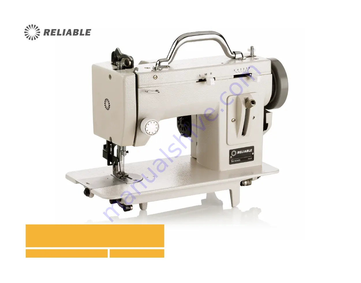
Page 1: ...INSTRUCTION MANUAL BARRACUDA 200ZW PORTABLE WALKING FOOT SEWING MACHINE ...

Page 2: ......

Page 3: ...anual MATERIAL IS OWNED BY RELIABLE AND MAY NOT BE REPRODUCED IN WHOLE OR IN PART WITHOUT EXPRESS WRITTEN PERMISSION FROM RELIABLE CORPORATION COPYRIGHT 2016 RELIABLE CORPORATION ...

Page 4: ...oat owners hobbyists and small businesses the Barracuda is ideal for medium to heavy weight sewing jobs SMALL SIZE BIG PERFORMANCE With a stitch quality comparable to an industrial machine there s no job too big for the Barracuda With top and bottom feeding it produces a perfect even stitch even when sewing over challenging materials ...

Page 5: ...p parts list Shuttle transmission group Shuttle transmission group parts list Feed transmission group Feed transmission group parts list Driving reversing mechanism group Driving reversing mechanism group parts list Electric power dynamic transmission group Electric power dynamic transmission group parts list ZigZag mechanism group ZigZag mechanism group parts list To regulate zigzag width and nee...

Page 6: ...speed This sewing machine can be mounted on a commercial stand To do so requires a special cut out table top a one inch 1 diameter pulley a special Balance Wheel Item No 11 and a maximum 1725 RPM motor OILING Before operating oil all metal to metal working parts and at the places indicated on diagrams below Use only genuine sewing machine oil Operate the machine briefly on scrap material after oil...

Page 7: ...135x17 needles size 10 to 23 Use size 22 for most medium to heavy sewing Install needle as illustrated THREAD To obtain the best results with your sewing machine we recommend size 69 Bonded Nylon Thread GROOVE 02 ...

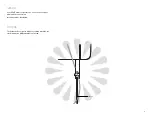
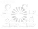
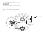
Page 8: ...WINDING THE BOBBIN 3 4 2 5 1 03 ...

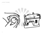
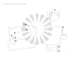
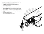
Page 9: ...THREADING THE MACHINE AND NEEDLE 3 6 4 5 2 1 7 8 6 5 04 ...

Page 10: ...through the eye of the needle with the fingers of the left hand Turn he balance wheel toward you with your right hand until the outside presser foot reaches its most backward position 3 Now operate the foot control to start sewing The above procedure is necessary so the motor will start the machine to sewing Do not help the feeding of the machine by hand as this may bend or break the needle Also d...

Page 11: ...Raise the stitch length feed regulator lever until the desired stitch length is obtained 3 Tighten the thumb nut REVERSE SEWING To sew in reverse 1 Lower the feed regulator stitch length lever all the way to the bottom of the slot in the stitch length plate 2 Hold the lever there until reverse sewing is completed 3 Then return the lever the forward position 6 5 4 3 2 1 0 FORWARD FEED REVERSE FEED ...

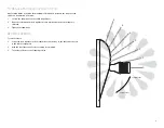
Page 12: ...ADJUSTING THE NEEDLE THREAD TENSION ADJUSTING THE bobbin TENSION 07 ...

Page 13: ...u 5 Remove retaining ring C and hook D by grasping the axle of the hook 6 Remove accumulated lint and thread from the retaining ring hook and race body 7 Replace hook D in race body with the axle facing out forming a perfect circle with the driver E 8 Replace retaining ring C polished side out so that both pins are under knobs A and B 9 Lock the retaining ring knobs A and B 10 Replace bobbin and b...

Page 14: ... and replace 5 Screw in hand clutch screw very light 6 Screw in stop screw 7 Back off on hand clutch screw 8 Run motor and check to see if balance wheel turns freely without running the machine 9 Tighten hand clutch screw and the machine should run properly BALANCE WHEEL CLUTCH WASHER CLUTCH STOP SCREW CLUTCH WASHER PRONGS ON CLUTCH WASHER POINT OUT WILL NOT WORK IF POINTED IN HAND CLUTCH SCREW SL...

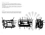
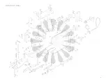
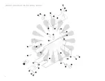
Page 15: ...CONSTRUCTIONAL 10 ...

Page 16: ...22 28 18 19 19 30 31 31 20 18 1 7 14 13 12 12 25 24 27 17 23 17 6 8 7 2 3 9 26 5 6 6 4 12 11 29 21 10 15 16 16 GROUP 1 CONSTRUCTION EXTERNAL GROUP 11 1 ...

Page 17: ...L PLATE COVER SET SCREW BOBBIN WINDER ASSEMBLY SET SCREW BOBBIN WINDER TENSION ASSEMBLY SET NUT BOBBIN WINDER TENSION ASSEMBLY SPOOL PIN ARM BODY BED NEEDLE BAR SUPPORT SET SCREW THREE HOLE THREAD GUIDE SET SCREW FACE PLATE FACE PLATE SET SCREW STITCH LENGTH PLATE STITCH LENGTH PLATE SET SCREW PART NAME BOBBIN WINDER SET SCREW NEEDLE PLATE NEEDLE PLATE SET SCREW SHUTTLE RACE SLIDE THREE HOLE THREA...

Page 18: ...17 11 1 2 3 8 38 4 7 37 27 12 4 26 13 25 19 27 28 35 18 16 24 10 9 6 5 14 23 16 15 21 20 31 22 30 34 32 29 33 4 GROUP 2 SEWING TRANSMISSION GROUP 28 1 13 ...

Page 19: ...CAM SET PIN CRANK ROD LEVER CAM FOLLOWER CRANK ROD LEVER CAM FOLLOWER ADJUST NUT CRANK ROD LEVER CAM FOLLOWER LOCK SCREW CRANK ROD LEVER CAM FOLLOWER LOCK NUT THREAD TAKE UP ASSEMBLY NEEDLE BAR CONNECTING ROD SET SCREW NEEDLE BAR CONNECTING ROD NEEDLE BAR CONNECTING STUD NEEDLE SET SCREW PRESSER REGULATING THUMB SCREW PRESSER REGULATING THUMB SET SCREW PRESSER BAR SPRING NEEDLE BAR SUPPORT PART NA...

Page 20: ...13 6 15 14 16 17 4 3 5 4 2 1 19 19 18 10 9 9 11 12 20 7 8 6 GROUP 3 SHUTTLE TRANSMISSION GROUP 15 ...

Page 21: ...W CRANK CONNECTING ROD SET NUT OSCILLATING SHAFT SET SCREW NUT OSCILLATING SHAFT SHUTTLE DRIVER PIN OSCILLATING SHAFT CRANK SET PIN OSCILLATING SHAFT CRANK SET SCREW OSCILLATING SHAFT CRANK WITH SLIDE BLOCK LOWER SHAFT COLLAR SHUTTLE RACE GUIDE SHUTTLE RACE GUIDE SHAFT SHUTTLE RACE GUIDE SHAFT SET SCREW SHUTTLE RACE GUIDE SHAFT COMPLETE LOWER SHAFT SHUTTLE DRIVER SHUTTLE HOOK BOBBIN BOBBIN CASE AS...

Page 22: ...9 8 10 11 13 18 15 17 17 1 15 16 11 11 23 22 19 14 11 21 20 12 1 2 3 5 24 7 6 4 GROUP 4 FEED TRANSMISSION GROUP 17 ...

Page 23: ... FEED REGULATOR FEED REGULATOR SPRING FEED REGULATOR SCREW SET SCREW FEED REGULATOR SCREW FEED CONNECTION SLIDE BLOCK FEED CONNECTION SLIDE BLOCK STUD FORKED ROD FEED ROCK SHAFT CENTER SCREW NUT FEED LIFTING ROCK SHAFT SCREW NUT DRIVING CRANK FEED ROCK SHAFT CRANK FEED ROCK SHAFT FEED BAR CENTER SCREW NUT FEED BAR FEED DOG FEED DOG SCREW DRIVING CRANK GUIDE NUT DRIVING CRANK GUIDE SCREW FEED LIFTI...

Page 24: ...16 17 15 16 14 18 26 12 11 8 7 24 23 25 6 4 3 5 1 2 22 21 38 34 38 37 35 36 33 37 38 32 31 32 38 42 41 40 39 30 30 29 28 27 29 19 20 9 10 10 13 GROUP 5 DRIVING REVERSING MECHANISM GROUP 17 1 19 ...

Page 25: ...R FOOT BRACKET OUTSIDE PRESSER FOOT BRACKET SCREW OUTSIDE PRESSER FOOT SET SCREW OUTSIDE PRESSER FOOT PRESSER BAR ACTUATOR FEED SCREW RING PRESSER BAR ACTUATOR FEED SCREW END PLATE END PLATE SET SCREW OUTSIDE PRESSER FOOT BRACKET LIMITATOR PART NAME BRACKET SET SCREW PRESSER BAR FEED ROD PRESSER BAR ACTUATOR SPACER END PLATE BEARING SET PLATE REVET BEARING BRACKET BUSHING LIFT CRANK ROD BEARING BR...

Page 26: ...28 26 23 23 25 25 24 22 24 4 5 6 3 15 14 19 18 17 13 12 11 10 9 7 8 1 21 2 20 21 27 28 GROUP 6 ELECTRIC POWER DYNAMIC TRANSMISSION 21 16 ...

Page 27: ...MOTION CLAMP STOP SCREW STOP MOTION CLAMP SCREW STOP MOTION CLAMP WASHER BALANCE WHEEL BUSHING BALANCE WHEEL BUSHING SET PIN HAND WHEEL BELT 130XLO 18 BELT 80XLO 25 E5 RING IDLE PULLEY SHAFT WASHER IDLE PULLEY SHAFT IDLE PULLEY IDLE PULLEY BEARING IDLE PULLEY LOCK WASHER IDLE PULLEY SET NUT PULLEY BRACKET MOTOR BRACKET SET WASHER MOTOR BRACKET SET LOCK WASHER MOTOR BRACKET SET SCREW BELT COVER BEL...

Page 28: ...15 14 16 27 1 7 25 6 22 5 3 20 2 4 25 17 11 18 21 19 25 8 24 13 12 11 24 10 6 25 23 25 GROUP 7 ZIG ZAG MECHANISM GROUP 23 ...

Page 29: ... NO M729 NEEDLE POSITION COMPLETE LEVER GUIDE SNAP RING 2 FOR NO 707 SPRING FOR NO M711 ZIG ZAG REGULATING LEVER PIN PART NAME ZIG ZAG CONTROL PLATE SET SCREW FOR NO 725 1 SET SCREW FOR NO M711 2 M729 1 M732 1 N747 1 H777 2 SET SCREW FOR NO M732 1 SET SCREW FOR NO 728 1 GROUP 7 TO REGULATE THE WIDTH OF ZIGZAG STITCH Moving the zigzag width lever to the desire zigzag width as marked on the panel ac...

Page 30: ...1 1 1 1 4 1 1 1 2 PART NAME HEAD SCREW BASE SlDE SET SCREW BASE SIDE PRESSER PLATE BASE SIDE PRESSER PLATE RUBBER BASE SHAFT SET SCREW BASE SHAFT BASE PRESSER PLATE BASE PRESSER PLATE RUBBER PRESSER PLATE SET SCREW SHIM SPRING BASE COVER PRESSER PLATE SET NUT RUBBER PACKING SIDE PRESSER PlATE SET SCREW BIG WORKING PLATE WORKING PLATE LEG BASE PLATE WORKING PLATE 26 ...

Page 31: ...tion stop screw with screw driver 2 By hand unscrew remove the stop motion screw 3 Remove clamp washer from under the stop motion screw 4 Remove the drive belt cover held by two screws 5 Remove longer main belt Turn hand wheel to assist removal 6 Remove the hand wheel Wheel slides off CUDA CRANK INSTALLATION 27 ...

Page 32: ...t Slip the drive belt over the BIG WHEEL first and then slip the belt over the small idle pul ley at the back Turn the small pulley slowly clockwise to make sure that the belt is properly in place 10 Put back in place the stop motion screw clamp motion washer Put back in place the stop motion clamp stop screw 11 Install the new belt cover on by two screws 12 For hand crank operation only install th...

Page 33: ...OPTIONAL CUDA CASE 3 4 plywood construction Reinforced metal corner guards Heavy duty handle Dual exterior case latches Separate insert houses the accessory kit for extra needles bobbins and more 29 ...

Page 34: ...le the Barracuda that for a period of three 3 years from the date of purchase it will be free from defects in materials and workmanship when utilized for normal use by the original purchaser only Subject to the conditions and limitations set forth below Reliable will either repair or replace any part of a Barracuda that proves defective by reason of improper workmanship or materials If the defecti...

Page 35: ...tation any liability for third party claims for damage and is limited to the amount paid by the original purchaser Reliable Product with respect to which this limited warranty protection applies This limited warranty does not apply with respect to products that have been altered or which are missing serial numbers or for products not purchased directly from Reliable or a dealer authorized by us to...

Page 36: ......

Page 37: ......

Page 38: ......

Page 39: ......

Page 40: ...1 800 268 1649 www reliablecorporation com ...

Reviews: