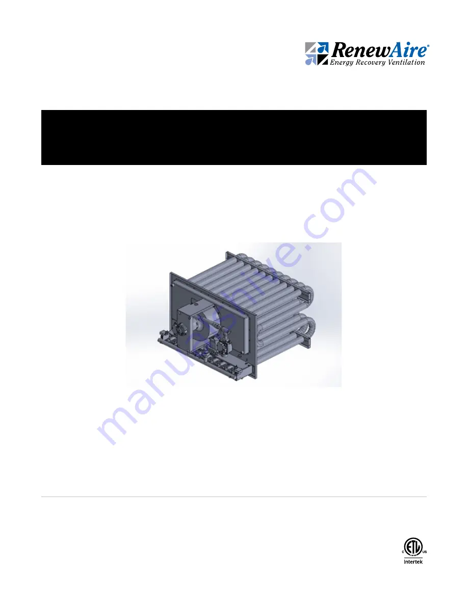
background image

Indirect Gas Heat Module Shown

DN-Series

Integral Indirect Gas-Fired Heat Module

Supplemental Manual for Options

Summary of Contents for HM-050

Page 1: ...Indirect Gas Heat Module Shown DN Series Integral Indirect Gas Fired Heat Module Supplemental Manual for Options ...

Page 2: ...r de gaz u Si vous ne pouvez joindre le fournisseur de gaz appelez les pompiers L installation at les réparations doivent être confiées à un installateur qualifié ou au fournisseur de gaz WARNING ARC FLASH AND ELECTRIC SHOCK HAZARD Arc flash and electric shock hazard Disconnect all electric power supplies verify with a voltmeter that electric power is off and wear protective equipment per NFPA 70E...

Page 3: ...rtures de bâtiment doivent être con formes aux codes locaux En l absence de codes locaux l installation doit être conforme au Code national du gaz combustible à la norme ANSI Z223 1 ou aux codes d instal lation Canadiens CAN CGA B 149 CAUTION Installation of wiring must conform with local building codes In the absence of local building codes installation must conform to the National Electric Code ...

Page 4: ...UAL NOTICE This manual contains essential information for the DOAS it is installed in Space for maintaining written records of heater maintenance and or repairs is in the DOAS IOM At the time the DOAS is commissioned a maintenance schedule should be developed by the user to incorporate monthly and seasonal maintenance and include start up maintenance tasks as described in this manual UNIT INFORMAT...

Page 5: ...LLATION 30 5 1 MODULE INSPECTION ON ARRIVAL 30 5 2 PREPARING FOR INSTALLATION 30 5 3 INSTALLATION CODES 30 5 4 PLACEMENT OF MODULE 30 5 5 CLEARANCES 30 5 6 MODULE INSTALLATION REQUIREMENTS 32 5 7 INSTALL SUPPLY AIR TEMPERATURE SENSOR 32 5 8 INSTALL GAS SUPPLY PIPING 32 5 8 1 Installation of Gas Piping 32 5 8 2 Determine Gas Supply Requirements 33 5 9 CONNECT CONDENSATE DRAIN 34 6 0 OPERATION 34 6 ...

Page 6: ...e and Pressure Chart 23 Figure 4 6 0 Example of Modulated Gas Train 26 Figure 4 7 0 Single Stage Gas Valves Typical 27 Figure 4 7 1 Two Stage Gas Valves Typical 27 Figure 4 7 2 Modulating Gas Valves Typical 28 Figure 5 6 0 Installation Example 32 Figure 5 8 0 Typical Data Label 33 Figure 5 8 1 Typical Gas Supply Piping Connection 33 Figure 5 9 0 Recommended Drain Trap Construction 34 Figure 6 2 0 ...

Page 7: ...al field wiring Line voltage readings between L1 and Neutral as well as L1 and Ground should be within 3 volts of the voltage rating on the module data label found on the front of the heat module 1 4 INPUT CAPACITY IN MBH W Gas module sizes are based upon the INPUT MBH thousands of BTUs per hour Watts This is a measure of heat energy available and is not to be confused with heat output which is af...

Page 8: ...e 2 stage and modulated See Section 4 7 Gas Valve Illustrations in this manual Every gas valve is normally closed NC and requires an activating signal from an ignition controller to activate the valve solenoid If the valve is 2 stage an additional signal from the signal conditioner is required to change the gas output to the second level or stage If the valve is modulating a variable analog signal...

Page 9: ...nd is therefore controlled by the on board Integrated Programmable Control 1 11 GAS HEATER OPERATION The heater receives high voltage power from the DOAS disconnect switch High voltage power from the unit disconnect switch runs to a step down transformer in the gas heat compartment Primary input voltage to the transformer is the unit voltage Secondary output voltage to the gas heat draft inducer b...

Page 10: ... 2 1 2 1 Vertically Vented Heat Modules Proper venting of the heat module is the responsibility of the installer Vent piping is supplied by others When operated with the venting system in place proper heat module operation must be verified including flue gas analysis of each connected module 1 Use single wall or double wall Type B vent pipe of diameters shown below INPUT RATING BTUh INPUT RATING W...

Page 11: ...ombustion products The total equivalent length of vent pipe must not exceed 50 feet 15 25 m Equivalent length is the total length of straight sections plus 5 feet 1 52 m for each 90 elbow and 2 5 feet 0 76 m for each 45 elbow The vent system must also be installed to prevent collection of condensate Pitch horizontal pipe runs downward inch per foot 21mm meter toward the outlet to permit condensate...

Page 12: ... in a reasonably airtight vestibule compartment as these systems provide combustion air from outside the heated space and vent the products of combustion outdoors Additionally the heating unit must include the following 1 A tooled door latch to ensure that door or panel is closed or in place during operation 2 Approved vent terminals on both the supply air inlet and flue gas exhaust NOTE The inlet...

Page 13: ... venting applications is approved for horizontal application Certain manufacturers vent terminals are approved for vertical installation only RenewAire LLC SCALE 1 30 SIZE DWG NO A BY DATE Vent FEB19 10 29 18 AND TOL ANSI Y14 5 CAH SURFACE FINISH FINISH DESCRIPTION OF REVISION TITLE LEVEL DN 3 IN GH SEPARATED VERTICAL VENT TOLL FREE 800 627 4499 DATE CHECKED BY 3 REMOVE ALL BURRS BREAK 63 MICROINC...

Page 14: ...the National Fuel Gas Code In Canada installation must be in accordance with CAN CGA B149 for natural gas and B149 2 for propane units Gas piping must be sized for the total BTU input of all modules serviced by a single supply Be sure that gas regulators servicing more than one modules have the proper pipe and internal orifice size for the total input of all modules serviced by the regulator See t...

Page 15: ...rical wiring must be done by qualified professionals in accordance with all applicable codes standards and licensing requirements Any structural alterations necessary for installation must comply with all applicable building health and safety code requirements When cutting or drilling into wall or ceiling do not damage electrical wiring and other hidden utilities Use the module only in the manner ...

Page 16: ...red by the DOAS low voltage 24 VAC transformer or external supplied 24 VAC transformer then follow the requirements for those transformers regarding wire length wire gauge and power draw This gas appliance must be electrically grounded in accordance with local codes or in the absence of local codes with the National Electrical Code ANSI NFPA and or the Canadian Electrical Code CSA C22 1 FOR MODELS...

Page 17: ...stomer Interlocks See Note EXA Valve 24V SIG YEL BLU BLU YEL 0 10 VDC Analag Iput Polarity Sensitive YEL YEL BLU RED BLK GRY BLU YEL IGNITION CONTROL L1 IND BLK BLK HI DRAFT INDUCER RED LO BLK WHT 4 2 Br W CR1 1 3 YEL Br W J1 Shunted See Notes for Dip Switch Setting 2 2nd ROLLOUT SWITCH ON HORIZONTAL BURNER TRAY ONLY CUSTOMER PROVIDED COMPONENT CUSTOMER FIELD WIRING INTERNAL TERMINAL CONNECTION 1 ...

Page 18: ...axitrol SC40 T1 T2 T3 T4 T5 T6 T7 T8 COM T9 HAPS EST R1 24V E Valve T10 T11 T1 T2 T STAT Factory Jumper Customer Interlocks See Note BLU EXA Valve 24V SIG YEL BLU BLU YEL 0 10 VDC Analag Iput Polarity Sensitive BLU YEL YEL BLU BRN BRN RED BLK GRY BLU YEL 2 2nd ROLLOUT SWITCH ON HORIZONTAL BURNER TRAY ONLY CUSTOMER PROVIDED COMPONENT CUSTOMER FIELD WIRING INTERNAL TERMINAL CONNECTION 1 EXTERNAL TER...

Page 19: ...LK RED M420 Mod Valve BLK YEL 24V R C 3 4 40VA BLU XFMR 2 BLU WHT FLAME SENSOR ROR IGNITER SPARK T2 T1 SC30 SM2AN PUR W PUR W Series 5 Ignition Control SPARK MV 24V APS T Stat SENSE Gnd V2 Gnd Syst Alarm 24VAC Alarm Indicator YEL YEL COM 2 STG GAS VALVE LO HI BLU Control Panel 2 PUR 5 BLU 6 BLU GRY RED W RED W T10 T11 YEL YEL SC30 SM2AN T9 T8 Section A Section B ROLL OUT SWITCH B ORG Ignition Cont...

Page 20: ...BLK BLK RED Mod Valve BLK YEL 24V R C 3 4 40VA BLU XFMR 2 BLU WHT FLAME SENSOR ROR IGNITER SPARK T2 T1 SC30 SM2AN PUR W PUR W Series 5 Ignition Control SPARK MV 24V APS T Stat SENSE Gnd V2 Gnd Syst Alarm 24VAC Alarm Indicator YEL YEL COM 2 STG GAS VALVE LO HI BLU Control Panel 2 PUR 5 BLU 6 BLU GRY RED W RED W T10 T11 YEL YEL SC30 SM2AN T9 T8 Section A Section B ROLL OUT SWITCH B ORG Ignition Cont...

Page 21: ...e WARNING RISK OF FIRE OR EXPLOSION Do not install heat module where it may be exposed to potentially explosive or flammable vapors Do not store or use gasoline or other flammable vapors and liquids in the vicinity of this or any module Do not install in potentially explosive atmosphere laden with dust sawdust or similar products RISK OF DAMAGE TO HEAT EXCHANGER AND PRODUCTION OF DANGEROUS GASES D...

Page 22: ... DO NOT SCALE DRAWING REMOVE ALL BURRS BREAK SHARP EDGES APPLICABLE STANDARDS DIM AND TOL ANSI Y14 5 UNLESS OTHERWISE SPECIFIED DIMENSIONS ARE IN INCHES TOLERANCES LINEAR 0 015 HOLE SIZE 0 005 ANGULARITY 3 SURFACE FINISH 63 MICROINCH MINIMUM DATE DRAWN BY CAH 10 29 18 DN IN GH Horiz Ductwork OCT1 SHEET 1 4510 Helgesen Madison WI 5371 TEL 608 221 4 FAX 608 221 2 TOLL FREE 800 62 TITLE CHECKED BY DA...

Page 23: ... 250 200 150 125 100 FIGURE 4 1 0 50 350 MBH TEMPERATURE AND PRESSURE CHART NOTE To convert Airflow CFM to l s 1 CFM 0 47 l s To convert MBH to Watts 1 MBH 293 Watts To convert F Temperature Rise to Celsius multiply the F by 0 5556 To convert the Pressure Drop in InWC to Pascals 1 Inch Water Column 248 8 Pascals NOTE Pour convertir le débit d air CFM en l s 1 CFM 0 47 l s Pour convertir MBH en Wat...

Page 24: ... required Input MBH using Input MBH 91 2 0 8 121 5 MBH Step 4 Select a module rated for the next larger input size which would be 125 MBH Once a module has been selected identify the correct module on the Temperature and Pressure chart shown on the previous page Each module is represented by two curved lines One curved line shows the temperature rise that the module produces at different airflow r...

Page 25: ...rsects with the Pressure Drop line for the desired module Use the example shown in Section 4 2 of this manual as an illustration 4 5 MODULE DATA CHART Temperature Rise Unit No of Tubes Input Rate Output Temperature Rise Air Flow Nom Duct Opening Vent Diameter Gas Train NPT Weight Installed Model No Qty Btu h Btu h Min Max Min Max D inch lb F F CFM CFM inch HM 050 3 50 000 40 000 20 60 617 1 852 5 ...

Page 26: ...IAL DO NOT SCALE DRAWING REMOVE ALL BURRS BREAK SHARP EDGES APPLICABLE STANDARDS DIM AND TOL ANSI Y14 5 UNLESS OTHERWISE SPECIFIED DIMENSIONS ARE IN INCHES TOLERANCES LINEAR 0 015 HOLE SIZE 0 005 ANGULARITY 3 SURFACE FINISH 63 MICROINCH MINIMUM DATE DRAWN BY CAH 6 25 18 250MBH Modulate SH 201 Ra Waunakee TEL 60 FAX 60 TOLL FREE TITLE CHECKED BY DATE S A GAS HEAT 10 1 V DN 3 EVEL DESCRIPTION OF REV...

Page 27: ...WHITE RODGERS 1 STAGE VALVE WHITE RODGERS 2 STAGE VALVE HONEYWELL 1 STAGE VALVE HONEYWELL 2 STAGE VALVE MANUAL SHUTOFF SWITCH GAS ADJUSTMENT SCREWS ELECTRICAL CONNECTION ELECTRICAL CONNECTIONS ELECTRICAL CONNECTION MANUAL SHUTOFF KNOB GAS ADJUSTMENT SCREW ELECTRICAL CONNECTION BLOCK MANUAL SHUTOFF SWITCH GAS ADJUSTMENT SCREWS ELECTRICAL CONNECTION BLOCK TECHNICAL DATA 1ST 2ND STAGE SOLENOID ELECTR...

Page 28: ...E 4 7 2 MODULATING GAS VALVES TYPICAL MAXITROL M SERIES MODULATING VALVE MAXITROL EXA SERIES MODULATING VALVE ELECTRICAL CONNECTION BLOCK BUTTON 1 HIGH FIRE DIP SWITCHES LED BUTTON 2 LOW FIRE ELECTRICAL CONNECTIONS LOW FIRE ADJUSTING SCREW UNDER PLASTIC CAP TECHNICAL DATA ...

Page 29: ...000 feet Option module burner orifices for operation over 7000 ft above sea level System Inducer Voltage Single Phase 115V Voltage Phase Single Phase only Control Voltage 24 VAC Standard secondary voltage Control Type Modulating 5 1 Turndown 3 1 turndown for propane module operates from 20 100 of output capacity based on 0 10Vdc input Modulating 10 1 Turndown 6 1 turndown for propane module operat...

Page 30: ... that installation of the DOAS with its gas heat module is installed safely in accordance with all applicable codes 5 5 CLEARANCES Clearances are as detailed on the Dimensioned Drawing of each unit type as applicable Dimensioned drawings are to be found in the DN Series IOM Sufficient space must be left in front of the DOAS to allow for servicing of the unit and its gas heater module This space wi...

Page 31: ...let must be a minimum of 2 5 feet above the roof deck and 6 feet from the nearest wall or adjoining building Horizontal venting The combustion air inlet must be positioned a minimum of 2 feet from the exterior wall and 3 feet above grade or expected snow depth The exhaust gas outlet must be located a minimum of 18 inches from the combustion air inlet and a minimum of 1 foot from the exterior wall ...

Page 32: ... temperature silicone caulking or high temperature tape to prevent leakage of circulating air All outdoor module duct connections must be weathertight to prevent rain and snow from entering the ductwork Support all ductwork securely DO NOT rely solely on module duct connections for support Provide removable access panels in ductwork immediately downstream of the heat module to allow for inspection...

Page 33: ...d Joint Union 8 in Trap Gas to Controls From Gas Supply Bleeder Valve or 1 8 in Plugged Tap Gas Cock FIGURE 5 8 1 TYPICAL GAS SUPPLY PIPING CONNECTION TYPE OF GAS REQUIRED MINIMUM PRESSURE REQUIRED NOTE When connecting the gas supply the length of the run must be considered in determin ing the pipe size to avoid excessive pressure drop Refer to a Gas Engineer s handbook for gas pipe capacities NOT...

Page 34: ... tapes are to be used it may be necessary to fabricate the trap and other drain piping from metal The drain trap should be filled with water or glycol solution prior to module start up OPERATION FIGURE 5 9 0 RECOMMENDED DRAIN TRAP CONSTRUCTION 6 0 OPERATION 6 1 GAS HEATER QUICK START GUIDE A wiring diagram and a Sequence of Operation are provided in the unit information package for each specific c...

Page 35: ...t is not a substitute for full configu ration of the controller NOTE Whenever the unit disconnect switch is turned OFF turn OFF the gas supply NOTE For further information on how to navigate the con troller see the Integrated Programmable Controller user manual ARC FLASH AND ELECTRIC SHOCK HAZARD Arc flash and electric shock hazard Disconnect all electric power supplies verify with a volt meter th...

Page 36: ...ed Pro grammable Controller user manual PATH HOME SCREEN SERVICE MENU UNIT TYPE ENABLE HEAT MUST BE YES HARDWARE SETTINGS Enable HGRH YES Enable Heat YES Enable Recirc YES Enable Defrost YES Enable Cool YES Service Menu I O Configuration I O Calibration Unit Type Test End Devices Back Up and Restore Sensor Overrides 6 2 4 Verify Heat Control Settings Go to Home Screen Control Variables Press ENTER...

Page 37: ...N and verify that the supply gas pressure is at least 5 0 InWC and not higher than 13 5 InWC for natural gas or 11 0 InWC to 13 5 InWC for LP gas Record the gas pressure in the chart on next page Shut off the gas at the gas supply line remove the manometer and replace the pressure tap plug With the unit disconnect switch OFF use the bleeder pressure tap on the main inlet valve and bleed the air fr...

Page 38: ... 5 InWC for Natural Gas and between 11 0 InWC and 13 5 InWC for LP Gas OBSERVED MANIFOLD GAS PRESSURE AT HIGH FIRE must be between 3 4 InWC and 3 5 InWC for Natural Gas and 10 0 InWC for LP Gas Single Manifold Pressure if applicable Split Manifold Pressure Left Side Split Manifold Pressure Right Side SPECIFY TYPE OF GAS AND PRESSURE OBSERVED 6 4 FAILURE TO IGNITE On the initial start up or after t...

Page 39: ...nformation Poor air supply can be caused by obstructions or blockage in heat exchanger tubes or vent discharge pipe Inspect and clean as necessary to eliminate blockage Vacuum any loose dirt or loose debris Clean heat exchanger tubes with a stiff brush Poor flame characteristics can also be caused by undersized combustion air openings or flue gas recirculation into combustion air supply Increase a...

Page 40: ...In order for the controller to provide a call for heat several controller menu items must be configured Hardware Settings Enable Heat YES This setting tells the controller that there is a heating device installed and that the controller should manage the operation of the heating device If this setting is left NO the controller will not provide any control signals Unit Status screens or Control Var...

Page 41: ...t is being sent into the Occupied Space The controller uses the air temperature sensor that was field installed on the Supply Air duct normally 4 6 feet downstream from the gas heat module Setpoint enter the desired temperature the controller should maintain IMPORTANT In normal heating operation the controller will prevent the heater from running when the Outdoor Air temperature is above the Locko...

Page 42: ...t the Call for Heat is being disabled because of the Lockout Above setting Shows that the controller wants to put out a 100 or 10 VDC Call for Heat Shows that the controller senses that the current temperature is lower than the setpoint Shows that the controller is supposed to maintain the setpoint of 72 F IMPORTANT Controllers that put out a variable Call for Heat require a means of anticipating ...

Page 43: ...etpoint is greater than the ambient temperature Note that when the appliance has received a call for heat a purge cycle will begin If the appliance fails to light the appliance will try three times to relight before going into a lockout condition 7 0 MAINTENANCE Annual maintenance This heat module should be inspected and serviced annually by a qualified service agency to assure proper operation An...

Page 44: ...heat rise at high fire u Return controller to normal setting If any of the original wiring needs to be replaced it must be replaced with wiring materials suitable for 105 C Label all wires prior to disconnection when servicing the unit Wiring errors can cause im proper or dangerous operation Verify proper operation after servicing CAUTION 7 3 SERVICE PARTS FIGURE 7 3 0 SERVICE PARTS MODULATED CONT...

Page 45: ...y be with the BMS not with the module 8 1 SEQUENCE OF OPERATIONS SOO Each heat module has a specific Sequence of Operation The SOO is printed separately and shipped with the module documentation package As an aid to understanding the operation of the heat module following is a GENERIC sequence of operation 1 Thermostat or heat enable closes and provides a call for heat powering T2 or T1 and T2 2 2...

Page 46: ... the module for a number of reasons and provide a flashing error code It also indicates the stages of ignition and correct operation ERROR CODE Solid Green Normal operation 1 Red Flash No Flame During Trial 2 Red Flashes Flame Sense Fail 3 Red Flashes Pilot Main Relay Fail 4 Red Flashes Multiple Flame Loss 5 Red Flashes Rollout Error 6 Red Flashes APS Airflow Error 7 Red Flashes Internal Control E...

Page 47: ... standard RenewAire ERV warranty A copy of the warranty is included with the unit manuals If the warranty should be lost or misplaced a PDF version can be downloaded from http www renewaire com support for the professional documentation warranty information In addition to the standard RenewAire warranty certain components in the heat module that are constructed of stainless steel such as the heat ...

Page 48: ...ability derived from innovative design practices expert workmanship and Quick Response Manufacturing QRM As the pioneer of static plate core technology in North America RenewAire is the largest ERV producer in the USA We re committed to sustainable manufacturing and lessening our environmental footprint and to that end our Waunakee WI plant is 100 powered by wind turbines The facility is also one ...

Reviews: