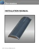
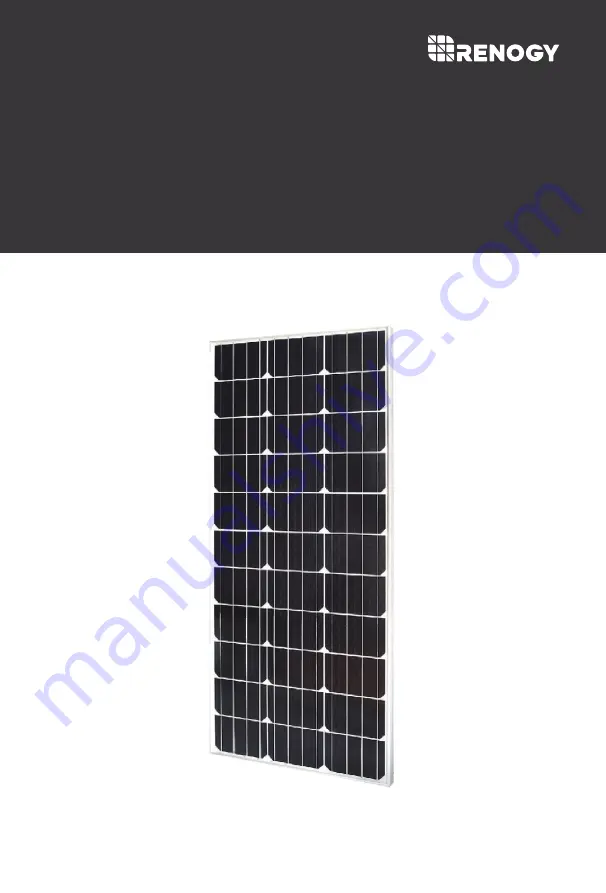
The Renogy RNG-100D is a high-quality solar panel renowned for its exceptional performance and durability. This product is backed by an extensive and user-friendly Installation Manual, which you can conveniently download for free from our website.
Version 1.0
INSTALLATION
GUIDE FOR
PHOTOVOLTAIC (PV) MODULES
Page 1: ...Version 1 0 INSTALLATION GUIDE FOR PHOTOVOLTAIC PV MODULES ...
Page 2: ...ation Considerations Unpacking and Storing Pre Installation Requirements Site Considerations Module Mounting Fastening Top Down Clamps Grounding Module Dimensions Electrical Installation Electrical Specifications Cables and Wiring Bypass Diodes General Installation Grid Connected Electrical System Commission and Maintenance Testing Commissioning and Troubleshooting Maintenance Replacing Bypass Dio...
Page 3: ...er any patent or patent rights The information in this manual is based on Renogy s knowledge and experience and is believed to be reliable but such information including product specification without limitations and suggestions do not constitute a warranty expresses or implied Renogy reserves the right to change the manual the PV produce the specifications or product information sheets without pri...
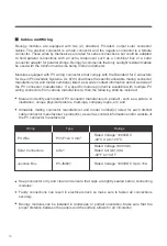
Page 4: ...n well away from the system while transporting and installing mechanical and electrical components Completely cover the module with an opaque material during installation to keep electricity from being generated Do not attempt to disassemble the module and do not remove any attached nameplates or components Do not apply paint or adhesive to the module top surface Do not use artificially concentrat...
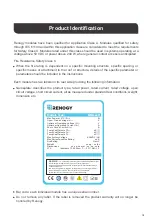
Page 5: ...weight dimension etc Do not remove any label If the label is removed the product warranty will no longer be honored by Renogy Bar code each individual module has a unique serial number Module Application Class A RNG xxD This module produces electricity when exposed to light Module Type Max Power at STC Pmax Open Circuit Voltage Voc Optimum Operating Voltage Vmp Optimum Operating Current Imp Temp C...
Page 6: ...ge the modules mechanically or electrically Modules can be wired in series to increase voltage or in parallel to increase current Series connections have the modules go from positive of one module to negative of the second module Parallel connections connect the positive and negative cables of one module and combine them to the second module Bypass diodes in the module is dependent on the model it...
Page 7: ...cked Operating Temperature within 40 F to 194 F Relative humidity within 45 to 95 Avoid trees buildings or obstructions Avoid shading even minor partial shading reduces yields Sunlight should be able to reach the module even on the shortest day of the year Shading can affect module service life The module should be facing true south in northern latitudes and true north in southern latitudes for be...
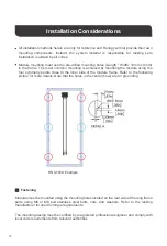
Page 8: ...ant authorities Fastening All installation methods herein are only for reference and Renogy will not provide their own mounting components Instead the system installer is responsible for making sure installation is abided by all codes Module mounting must use the pre drilled mounting holes Length Width 14mm x 9mm in the frame The most common mounting is achieved by mounting the module using the fo...
Page 9: ...Top Down Clamps Use appropriate corrosion proof fastening materials should be stainless steel Do NOT drill holes or modify the module frame as it will void warranty Each module must be securely fastened at a minimum of 4 points on two opposite sides Actual bolt depends on the railing and professional installer Design load and safety factors will be determined by racking suppliers or professional e...
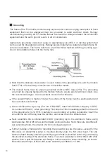
Page 10: ...t connector for this wire We recommend the lay in lug Cat No GBL4 DBT rated for 600Volts company ILSCO UL number is E34440 when grounding First strip the 16mm insulating jacket from the end of the ground wire 4 14 STR carefully to avoid nicking or cutting conductors insert the wire into the slot of the lug see the picture and screw down the slotted screw Next assemble the recommended ILSCO groundi...
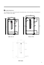
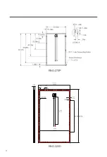
Page 11: ...in 600mm 23 6in 464mm 18 3in 1031mm 40 6in 1076mm 42 4in 35mm 1 38in 39mm 1 54in 39mm 1 54in 50mm 1 97in 50mm 1 97in 200mm 7 87in 200mm 7 87in 14 9mm 0 35in 2 0mm 0 08in 668mm 26 3 in 140mm 5 51 in 50mm 1 97 in 39mm 1 54 in 39mm 1 54 in 50mm 1 97 in 300mm 11 8 in 300mm 11 8 in 50mm 1 97 in 39mm 1 54 in 1326mm 52 2 in 39mm 1 54 in 50mm 1 97 in 623mm 24 5 in 700mm 27 6 in 14 9mm 0 35 in 2 0mm 0 08 i...
Page 12: ...11 RNG 320D 13 mm 0 5 in 35 mm 1 4 in 1002 mm 39 4 in 55 mm 2 2 in 900 mm 35 4 in 992 mm 39 1 in 1665 mm 65 6 in 35 mm 1 4 in 958 mm 37 7 in 6 mm 0 24 in Grounding 14 5 6 5mm 0 57 0 26 in RNG 270P ...
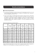
Page 13: ...rked on this module should be multiplied by a factor of 1 25 when determining component voltage ratings conductor ampacities fuse sizes and size of controls connected to the PV output Additional multiplier of 1 56 may be applicable when sizing conductors and fuses Electrical characteristics are displayed below Module RNG 300D 300 32 25 9 33 39 82 9 78 1000 RNG 160D 160 20 2 7 92 22 9 8 37 600 RNG ...
Page 14: ... sure that the proper distance between the panels and the surface allows for air circulation Cables and Wiring Renogy modules are equipped with two 2 stranded PV rated output solar connector cables The positive connector is a male connector and the negative connector is a female connector These wires by themselves are rated for series connections but could be adapted to hold parallel connections w...
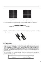
Page 15: ...e wired in parallel with the PV string cells In the event the modules experience partial shading the diodes are activated to bypass the current generated by the non shaded cells therefore limiting module heating and performance losses However they do not protect the panel from over current Over current protection devices must be used when connecting more than 2 modules in series If the bypass diod...
Page 16: ...erated by photovoltaic systems may also be converted to AC and connected to a utility grid system As local utilities policies on connecting renewable energy systems to their grids vary from region to region consult a qualified system designer or integrator to design such a system Permits are normally required to install such a system and the utility must formally approve and inspect such a system ...
Page 17: ...ttention the rated scale of the ammeter or the rated current of load should be more than 1 25 times than the rated short circuit current of series module You will find the rated current in the technical specifications of the type of module used The measured value can vary significantly depending on weather conditions the time of day and shading of the module Testing modules connected in series bef...
Page 18: ...face down on a soft flat surface Insert a 3mm flat screwdriver into the slot on the junction box cover The cover has a sign of screwdriver Gently pull up the four slots until the cover has been opened Note the orientations of the polarity markings on the diodes Insert the 3mm flat screwdriver into a hole alongside the diode and near one mounting hole of the diode pry the screwdriver in the opposit...
Page 19: ... diode with a diode of the same type and ensure that its polarity making is oriented the same way as the original diode Finally check the open circuit voltage Voc of the module as described previously and replace both covers ...
Page 20: ...909 287 7111 www renogy com support renogy com https www renogy cn support renogy cn CN 400 6636 695 苏州高新区科技城培源路1号5号楼 4 CA https ca renogy com supportca renogy com https au renogy com supportau renogy com AU JP https www renogy jp supportjp renogy com https uk renogy com supportuk renogy com UK https de renogy com supportde renogy com DE ...