Rev A Date: 02/24/2022
User Manuals\Reveal_NR(L)(H)HSSV_Free-Standing_Heated Self-Service Cases 21-26055.pub
SCC P/N
21-26055
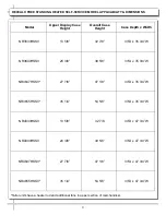
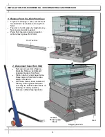
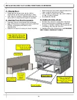
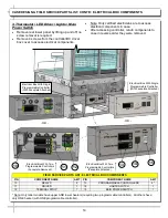
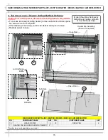
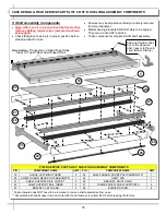
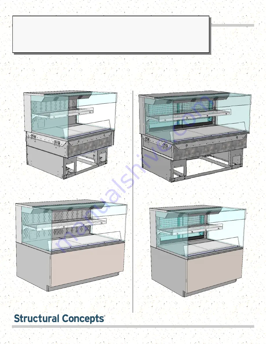
REVEAL® FREE-STANDING SELF-SERVICE HEATED MERCHANDISERS
> REAR SLIDING DOOR UNITS WITH PERFORATED PLENUMS THAT SLIDE IN TANDEM WITH DOORS
> SOLID BACK UNITS WITH FIXED METAL PERFORATED PLENUM
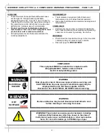
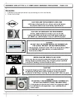
> CAUTION! DO NOT PUSH OR PULL ON UPPER GLASS ENCLOSURE!
> ONLY USE HANDLES (AT EACH END OF CASE) TO PUSH OR PULL CASE INTO POSITION!
> SEE PAGES 10-11 FOR FRONT/SIDE PANEL/REAR PANELS & TOE-KICK ATTACHMENT INSTRUCTIONS
Reveal
®
READ AND SAVE THESE INSTRUCTIONS
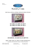
Model NR3640HSSV Free Standing Unit With Rear
Sliding Doors Shown WITH Front/Side/Rear
Cladding and Toe-Kick Attached
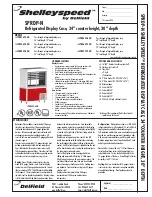
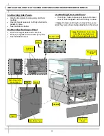
Model NR4840HSSV Free Standing Unit With Rear
Sliding Doors Shown WITHOUT Front/Side/Rear
Cladding And Toe-Kick Attached
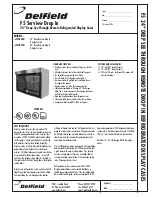
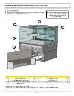
Model NR4840HSSV Free Standing Unit With
Solid Back Shown WITH Front/Side/Rear
Cladding and Toe-Kick Attached
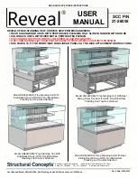
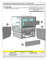
Model NR3640HSSV Free Standing Unit With
Solid Back Shown WITHOUT Front/Side/Rear
Cladding and Toe-Kick Attached
Structural Concepts Corporation ∙ 888 E. Porter Road ∙ Muskegon, MI 49441
Phone: 231.798.8888 ∙ Fax: 231.798.4960 ∙ www.structuralconcepts.com
USER
MANUAL