background image

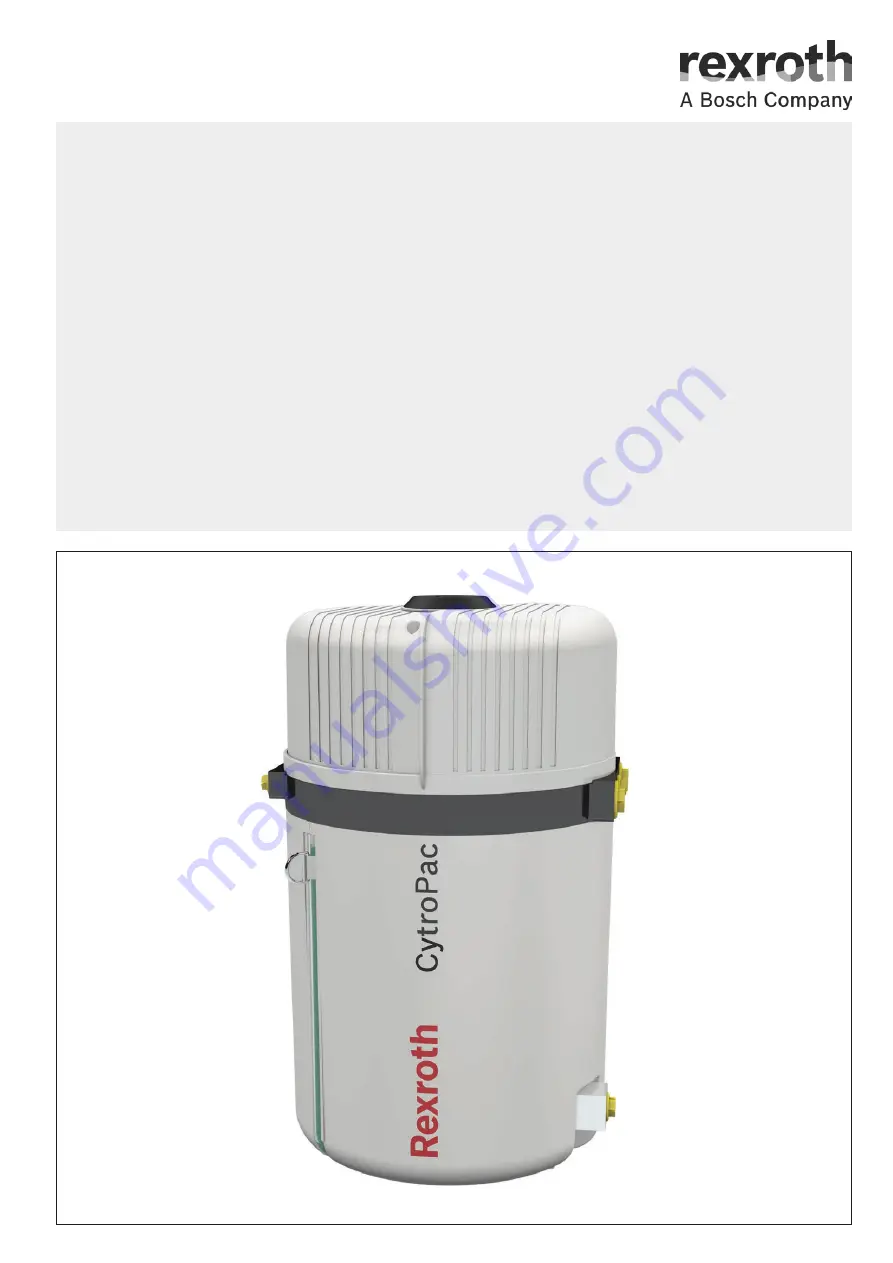
Operating instructions
RE 51055-B/02.2021

Replaces: 

06.17

English

Small power unit

CytroPac

Summary of Contents for CytroPac

Page 1: ...Operating instructions RE 51055 B 02 2021 Replaces 06 17 English Small power unit CytroPac ...

Page 2: ...ligation of own judgment and verification It must be remembered that our products are subject to a natural process of wear and aging This document as well as the data specifications and other information set forth in it are the exclusive property of Bosch Rexroth AG It may not be reproduced or given to third parties without its consent The cover shows an example configuration The product supplied ...

Page 3: ... diagram hydraulic 22 5 5 Identification of the product 23 6 Transport and storage 24 6 1 Transporting the hydraulic power unit 24 6 1 1 Preparing for transport 25 6 1 2 Transport using forklifts and similar industrial trucks 25 6 1 3 Transport using lifting gear 26 6 2 Storing the hydraulic power unit 27 7 Mounting 28 7 1 Unpacking the hydraulic power unit 28 7 2 Erecting the hydraulic power unit...

Page 4: ...4 Maintenance schedule 52 10 5 Maintenance 53 10 5 1 Checking the electrical components installation 53 10 5 2 Fill level monitoring 53 10 5 3 Monitoring of the oil temperature 54 10 5 4 Filter element clogging monitoring return flow filter 54 10 5 5 Visual inspection of the filler breather filter see Fig 31 item 6 55 10 5 6 Pressure value check 55 10 5 7 Hydraulic fluid care 55 10 5 8 Visual insp...

Page 5: ...RE 51055 B 02 2021 Bosch Rexroth AG 17 2 1 Annex to declaration of incorporation 66 17 3 Restricted substances REACH RoHS WEEE 67 17 4 Accessories 68 17 5 Additional document for UL Listing 70 18 Alphabetical index 72 ...

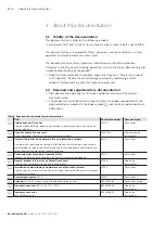
Page 6: ...mentation Title Document number Document type Small power unit CytroPac Contains technical data operating conditions performance limits and notes on project planning 51055 Data sheet CytroPac hydraulic power unit Basic Advanced Premium Commissioning instructions 51055 IB Commissioning instructions Hydraulic fluids based on mineral oils and related hydrocarbons Describes the requirements for hydrau...

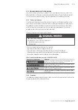
Page 7: ...Type and source of danger Consequences in case of non compliance Hazard avoidance measures Enumeration Warning symbol draws attention to a hazard Signal word identifies the degree of hazard Type and source of danger Specifies the type and source of danger Consequences describes the consequences in case of non compliance Precaution Specifies how the danger can be prevented Table 2 Hazard classifica...

Page 8: ...ered instruction The numbers indicate that the actions must be carried out one after the other 1 3 3 Abbreviations used The following abbreviations are used in this documentation Table 4 Abbreviations Abbreviation Meaning AB Aggregatebau power unit construction BR Bosch Rexroth DBV Druckbegrenzungsventil pressure relief valve NG Size PE Protective Earth RE Rexroth document in English language REXX...

Page 9: ...conducted an independent risk assessment Furthermore the manufacturer must on this basis have prepared operating instructions for the complete machinery system These operating instructions do not serve as replacement of the operating instructions of the overall machinery system 2 2 Intended use The hydraulic power unit is a hydraulic system component You may use the product as follows The hydrauli...

Page 10: ...fication of personnel The activities described in this documentation require basic knowledge of mechanics electrics and hydraulics as well as knowledge of the appropriate technical terms For transporting and handling the hydraulic power unit additional knowledge of how to handle lifting gear and the necessary attachment devices is required In order to ensure safe use these activities may only be c...

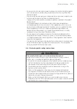
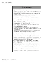
Page 11: ...tional regulations safety regulations and standards relevant for the application Only persons who have been authorized by the machine end user may be granted access to the direct operating range of the machine system This also applies during any standstill of the machine system 2 6 Product specific safety instructions WARNING Pressurized hydraulic power unit pressurized machine system Danger to li...

Page 12: ...ids you must imperatively observe the notices of the manufacturer When carrying out welding work on the system make sure that the grounding electric welding circuit is not lead via the hydraulic power unit Unexpected start up due to malfunctions incorrect operation Danger to life Risk of injury Ensure that the hydraulic power unit is secured against unexpected start up Regularly check the hardware...

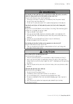
Page 13: ...rce of interference Provide for proper safe PE connection Overheating of electrical cables and components or short circuit Danger to life Risk of injury Risk of fire Observe the operating conditions and performance limits and safeguards specified in the technical data CAUTION Hot surfaces of the hydraulic power unit Risk of injury Risk of burning Allow the hydraulic power unit to cool down suffici...

Page 14: ...ctive equipment Loud noise due to excessively high sound pressure level in case of malfunction Risk of hearing damage temporary permanent stress loss of attention Fault in voice communication and acoustic signals Wear your hearing protection Consult the machine manufacturer or Bosch Rexroth to identify any malfunction if applicable 2 7 Personal protective equipment During operation and maintenance...

Page 15: ... of factory security officers and of the operating instructions of the machine end user Behavior in case of emergency The operation of installations systems and machines basically requires the implementation of a holistic IT security concept which is state of the art in terms of technology Accordingly Bosch Rexroth products and their properties must be considered as components of installations sys...

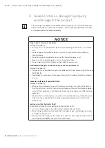
Page 16: ...o property Parameters may only be changed in accordance with commissioning instructions RE 51055 IB Coordinate any changes of other parameters with the Bosch Rexroth customer service Operation with lack of hydraulic fluid Damage to property When commissioning or re commissioning a machine or system make certain that the oil tank as well as the suction and working lines of the hydraulic power unit ...

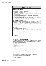
Page 17: ...lic connections are plugged or connected Before commissioning ensure that all hydraulic and mechanical connections have been made Make sure that no contaminants penetrate when closing the measuring ports Improper cleaning Damage to property Cover all openings with the appropriate protective plug screws in order to prevent cleaning agents from penetrating the system Check that all seals and electri...

Page 18: ...2021 4 Scope of delivery The following is included in the scope of delivery Hydraulic power unit CytroPac Operating instructions this document including EC declaration of incorporation For further information on optional components refer to chapter 17 4 Accessories ...

Page 19: ...s as sensor node and bundles all measured values of fill level temperature and filter clogging sensors and forwards these values via a multi Ethernet interface e g Sercos or PROFINET to the machine control This ensures reading of all parameters required for condition monitoring The CytroPac can be easily integrated in Industry 4 0 applications The status of the hydraulic power unit is also indicat...

Page 20: ... monitoring of pump CytroPac sensor monitoring Advanced and Premium CytroPac only LED blinking pattern showing converter status Advanced and Premium CytroPac only 5 2 Product description The CytroPac is a frequency controlled hydraulic power unit consisting of a frequency converter electric motor hydraulic pump oil tank cooling system and sensorics The cooling system consists of the heat exchanger...

Page 21: ... flow filter 4 Filter clogging sensors 5 Fill level and temperature sensor 6 Filler breather filter 7 Cover with frequency converter below 8 Electrical connections see figs 19 to 21 9 Visual oil level check and hydraulic fluid draining Hydraulic fluid hose with LED strip for status display for information on the meaning of the LED signals see chapter 10 3 Warning devices Advanced and Premium confi...

Page 22: ...r Filter clogging sensor 75 Filter clogging sensor 100 Fill level and temperature sensor Filler breather filter Frequency converter Cooling package optional Visual oil level check and hydraulic fluid draining Pressure cell Check valve Filling coupling optional Electrical connections figs 19 to 21 a Sensor configuration Basic 12X1 Feed in voltage supply 14X1 Mini USB service interface 15X1 Enable s...

Page 23: ...m temperature 6 Country of origin 16 UL enclosure rating 7 Rated pressure 17 UL text 8 Plant 18 UL mark Underwriter Laboratories Inc 9 Date of production 19 QR code 10 Maximum displacement 20 Company data MNR R900500018 FD 16W51 Made in Germany Bosch Rexroth AG DE 97816 Lohr Hotline 49 9352 405060 www boschrexroth com service SWN R901879658 CYTROPAC 7089 Rexroth Service the Original U N AC 380 480...

Page 24: ...r unit cannot fall due to its decentralized center of gravity Transport the hydraulic power unit using an industrial truck or suitable lifting gear For fixation and lifting of the hydraulic power unit with lifting gear only use the eyebolt provided for this purpose Transport the hydraulic power unit in an upright position using an industrial truck Observe the maximum load bearing capacity of the a...

Page 25: ...t For transportation after operation drain the hydraulic fluid from the oil tank To prevent air in the suction line a low level of hydraulic fluid is always inside the tank 6 1 2 Transport using forklifts and similar industrial trucks To transport the hydraulic power unit using a forklift proceed as follows 1 Move the fork of the forklift under the packaging of the hydraulic power unit or under th...

Page 26: ...is sufficiently dimensioned in order to safely bear the weight of the hydraulic power unit 2 Use the eyebolt which is mounted to the hydraulic power unit and provided for lifting see fig 5 3 Make sure that the eyebolt is securely tightened 4 Make sure that the cover is turned to the closed position during transport See fig 5 5 Attach suitable lifting gear to the eyebolt 6 Attach the lifting gear t...

Page 27: ...power unit protected against shocks Store the hydraulic power unit in an upright position Make sure that the cover of the hydraulic power unit is closed during storage The maximum storage time of the hydraulic power unit is 12 months If the storage time exceeds 12 months check the function of the hydraulic power unit and flush it with suitable cleaning liquid prior to commissioning Carry out flush...

Page 28: ... of injury Damage to property Make sure that the hydraulic power unit is erected and installed exclusively by qualified personnel see chapter 2 4 Qualification of personnel Observe the information on handling the product in chapter 6 Transport and storage Position the hydraulic power unit on a suitable foundation Observe the specifications on the total weight NOTICE Damage to the surface oil tank ...

Page 29: ...n a damping mat Make sure that the hydraulic power unit is secured against falling Align the hydraulic unit so that it is horizontal in the longitudinal and transverse axes 7 2 1 Dimensions of the hydraulic power unit Fig 6 Dimensions given in mm according to DIN ISO 1179 2 63 5 610 405 X D G1 2 D G1 130 D G1 130 K G 1 2 366 P G1 2 Dimension X pressure port P NG of the installed pump 65 AS04 64 AS...

Page 30: ...e the hydraulic power unit on the mounting plate Thanks to the embossed locking mechanisms the hydraulic power unit slides on the mounting plate If the hydraulic power unit is not positioned completely on the mounting plate like illustrated in Fig 14 und Fig 15 but on the locking mechanisms the hydraulic power unit can be slightly rotated into the correct position Mount the hydraulic power unit wi...

Page 31: ...Mounting 31 76 CytroPac RE 51055 B 02 2021 Bosch Rexroth AG Fig 8 Mounting steps 1 and 2 Fig 9 Mounting steps 3 and 4 Fig 10 Mounting step 5 1 2 n 162 4x 3 4 5 ...

Page 32: ...32 76 Mounting Bosch Rexroth AG CytroPac RE 51055 B 02 2021 Fig 11 Mounting step 6 Fig 12 Mounting step 7 6 7 2 Nm ...

Page 33: ...raulic power unit to the mounting plate Fig 14 Mounting position of the screw Fig 15 Mounting orientation of the mounting plate 1 1 1 Screw M6 x 430 3 Clip bent by 90 4 Locking mechanisms 5 Tapped hole for M6 x 430 screw 6 4 x ø9 through hole for hexagon socket head cap screw e g M8 x 20 3 4 5 6 ...

Page 34: ... Install the hose lines without any tension stress Remove the blanking plugs plastic and replace them by pressure resistant fittings Observe the installation information of the fitting manufacturers to prevent any external leakage Bosch Rexroth recommends fittings with elastic seals Install the flexible hoses in such a way that kinking and tensile stress at the hose is prevented during operation t...

Page 35: ...by whipping the installation of a hose safety catch is recommended If the flexible hose lines are equipped with tear proof fittings a hose safety catch is not required 7 4 Connecting the water supply For motor and frequency converter cooling the hydraulic power unit must be connected to a cooling water supply Route the lines to the intended cooling water ports see Fig 17 item 1 and connect them ac...

Page 36: ...engineering Make sure that the power supply is disconnected and also safeguarded against being switched on unintentionally Prevent unintended activation by means of a warning sign indicating that work is carried out at the electrical system For operation of the hydraulic power unit at least the following electrical connections are required 1 12X1 Feed in voltage supply Fig 18 2 15X1 Enable signal ...

Page 37: ...age 68 7 5 1 Pinout of the mating connector to connection 12X1 Feed in voltage supply Assign the pins of the mating connector optional accessory item see chapter 17 4 Accessories on page 68 for the power supply as shown in Fig 18 Make sure that the supply connection complies with the below specified requirements Fig 18 Feed in voltage supply Feed in voltage supply including fuse and mains contacto...

Page 38: ... for external enable Hydraulic power unit is put into operation Pin 4 0 VDC reference ground pin 1 Pin 5 24 VDC input for acknowledgment of faults errors Pin 6 Advanced and Premium configuration only Pin 7 and pin 8 24 VDC inputs can be configured to select different pressure stages for example Fig 20 Pinout of port 15X1 Enable signal 24 VDC Basic configuration 15X1 1 2 3 4 5 6 7 8 1 2 3 4 5 6 7 8...

Page 39: ...Filter clogging sensor 100 Pin 1 24 VDC supply Pin 3 24 VDC output for filter clogging shutdown normally closed contact In Basic configuration the three sensors must be wired to the higher level machine control system for evaluation In case of shutdown the enable signal of the hydraulic power unit must be canceled In the Advanced and Premium configuration the warning and shutdown signals are inter...

Page 40: ...able Hydraulic power unit is put into operation Pin 4 0 VDC reference ground pin 1 Pin 5 24 VDC input for acknowledgment of faults errors Pin 6 24 VDC output for warning e g filter clogging oil level temperature Pin 7 and pin 8 24 VDC inputs can be configured to select different pressure stages for example Fig 22 Pinout of port 15X1 Enable signal 24 VDC Advanced and Premium configuration 15X1 1 2 ...

Page 41: ... 6 Multi Ethernet interfaces In the Premium configuration the hydraulic power unit can be connected to the higher level machine control system via the multi Ethernet interfaces 21X1 item 15 and 21X2 item 16 see Fig 24 below The 21X1 interface network input is always to be connected The 21X2 interface network output can be used to connect further devices If not used plug the connection to maintain ...

Page 42: ...motor can be safely interrupted In this case the drive cannot generate any force and as a consequence it cannot generate any dangerous motions either This safety function corresponds to stop category 0 according to IEC 602041 Also observe operating instructions R912005854 for frequency converter series EFC x610 22X1 Fig 25 Port 22X1 STO Table 6 22X1 Safe Torque Off STO Pin Function Connector M12x1...

Page 43: ...having established the feed in connection and prior to switching on the protective grounding conductor connection to the power unit particularly check the central plate verification by means of test records according to DIN EN 60204 1 VDE 0113 1 end to end connection of the protective grounding conductor system or DIN VDE 0701 0702 protective grounding conductor inspection Fig 26 Electrical connec...

Page 44: ...ation To connect the power supply proceed as follows Connect the filter clogging indicators see Fig 27 items 4 1 and 4 2 as well as fill level and temperature sensor item 5 to be provided by customer Connect the connector plug for the enable interface via port 15X1 with the higher level machine control Connect the connector plug for the feed in voltage supply to port 12X1l 14X1 12X1 15X1 5 4 1 4 2...

Page 45: ...the enable interface via port 15X1 with the higher level machine control Connect the connector plug for the feed in voltage supply to port 12X1l 7 6 3 Premium configuration In the Premium configuration all ports are available Fig 29 Electrical connections of Premium configuration Connection 22X1 is optional see 7 5 7 Additional port Safe Torque Off STO 22X1 optional on page 42 To connect the elect...

Page 46: ...is not provided and protection class IP67 is not reached Protect interfaces that are not used with the associated protective cap 7 6 4 All configurations To connect the Mini USB service interface proceed as follows Connect the hydraulic power unit with a mini USB cable Bosch Rexroth recommends a shielded cable with ferrite ring via the mini USB service interface to a PC The CytroPac is equipped wi...

Page 47: ...oning must not be undertaken until it has been determined that the machine to be equipped with the hydraulic power unit complies with the provisions of all relevant directives The combination of components may lead to additional other types of hazards For commissioning of the hydraulic power unit strictly observe the operating instructions of the overall machinery system This particularly applies ...

Page 48: ...lling coupling at the hydraulic power unit as illustrated in Fig 30 Replace the air filter included in the construction kit by the filler breather filter and ensure that filling is no longer realized via the air filter The fill level must be within the marking on the fill level indicator Fig 30 Filling options Recommendation Experience has shown that the cleanliness class required for operation of...

Page 49: ...e targeted condition after flushing Preparations Provision of replacement or flushing filter elements As required Provision of additional pipe and flexible hose material for flushing and short circuit links Provision of flushing plates alternatively directional valves As applicable Provision of flushing fluid see notice below The same medium can be used as in later operation of the hydraulic syste...

Page 50: ...ust be restored flushing connections removed and connections closed pressure tight 8 2 Re commissioning after longer standstill For re commissioning after longer standstill proceed as follows Check the hydraulic fluid level hydraulic components and line systems for tightness Switch on components with increased caution Bleed the hydraulic system Observe the information in the operating instructions...

Page 51: ... immediate inspection of the machine system For further information on the scope and time intervals for maintenance and repair of the overall machine system please refer to the operating instructions of the machine system manufacturer 10 1 Cleaning and care For cleaning and care of the hydraulic power unit observe the following Make sure that all seals and electric plug in connections are firmly f...

Page 52: ...D The exact error message may be read out via the Mini USB service interface and software or IndraWorks Ds 10 4 Maintenance schedule Observe the status display for oil filter oil level oil temperature and oil change of the LED strip at the hydraulic power unit Table 7 Maintenance schedule Activity maintenance interval 1 2 y 1 y Alternative Operating hours Visual inspection External leakage crackin...

Page 53: ... shutdown of the hydraulic power unit must be ensured if the level has fallen below the shutdown limit 1 Expansion due to increase in temperature Rough calculation Delta V thermal expansion coefficient x delta T Correct the fill level 2 Exceeding of the maximum fill level due to presumed water ingress Close water valves shut off the cooling water supply Take a hydraulic fluid sample from the botto...

Page 54: ... not indicate any change over multiple inspection intervals Of course this may always be an indicator that the hydraulic fluid is clean However it may also have the following causes The clogging indicator is defective The filter element is defective Plan and carry out replacement of the filter element at the end of the shift Shorten the intervals between the required replacement of filter elements...

Page 55: ... drive behavior e g increased cycle time end product quality etc Otherwise at least semi annual inspections are recommended Bosch Rexroth recommends that the pressure values be noted in the maintenance documentation 10 5 7 Hydraulic fluid care The hydraulic fluid should be analyzed at least annually For analyzing the hydraulic fluid a proper hydraulic fluid sample must be taken The hydraulic fluid...

Page 56: ... occurs at this position the contact must be thoroughly checked for the cause of leakage Depending on the result seals and or the component must be replaced In case of cracking and resulting leakage the cause must be identified and corrected Afterwards affected components must be replaced or thoroughly repaired In case of indications of external force effects the cause must be identified and corre...

Page 57: ...ülleinrichtung kann separat bestellt werden Material Nr R901460916 Option filling can be ordered separately Material no R901460916 Zeichnungs Nr RA63234329 AB Typenschlüssel Z3D CytroPac 1X Standardabbildung Abweichungen möglich Standard illustration variations possible Material number Denomination Remark Assembly R928035258 35 0035CP H10XL R00 0 M Filter element 1930 R901473309 ASSEMBLY KIT CYTRO...

Page 58: ...plicable instructions for the overall machine system Unless these operating instructions provide different information proceed as follows Prevent hazards posed by adjacent machines Unauthorized personnel must not be allowed access to the working area Lower and securely support all loads 11 2 Decommissioning process Switch off the power supply and secure the system against restarting Switch off the...

Page 59: ...c power unit is to be transported after demounting Please note that the hydraulic power unit may be mounted on an optional mounting plate see Fig 15 To remove the hydraulic power unit from the mounting plate loosen the screw see Fig 13 Safety measures Always observe applicable instructions for the overall machine system Unless these instructions provide different information proceed as follows Car...

Page 60: ...ed responsible for any extensions to or modifications of the product If you undertake any extensions to or modifications of the product marketed by Bosch Rexroth this means you are changing the condition as supplied Any statements made by Bosch Rexroth regarding this product will then become invalid For hydraulic power units this has the following consequence Hydraulic power units are partly compl...

Page 61: ... for troubleshooting Always work systematically and purposefully even when under time pressure Random and imprudent disassembly and readjustment of settings can in the worst case scenario result in the inability to determine the original cause of error First get a general idea of the function of the hydraulic power unit in combination with the overall machinery system Try to find out whether the h...

Page 62: ... hoses of larger nominal widths Pressure command value is not reached or insufficient flow Speed limit too low As applicable change the flow limitation parameter F1 12 You can find further information in the commissioning instructions 51055 IB see flow command value Overloading of frequency converter in operation Drive insufficiently dimensioned Make sure that the operating point is within the cha...

Page 63: ...ts of the technical specifications Increased efficiency losses due to changed conditions including wear Carry out maintenance and replace affected components as necessary Increased filter clogging Ingress of dirt due to insufficient cleaning of components during installation Flush the hydraulic system Deposition of dirt when filling in hydraulic fluids Fill the hydraulic system via a filling unit ...

Page 64: ...in Germany Phone 49 0 9352 40 50 60 E mail service boschrexroth de Outside Germany you will find service subsidiaries in your vicinity on the Internet at www boschrexroth com Bosch Rexroth AG Zum Eisengiesser 1 97816 Lohr am Main Germany Phone 49 0 9352 40 30 20 Email my support boschrexroth com The addresses of our sales and service network and sales organizations can be found at www boschrexroth...

Page 65: ...erden Hier nicht angegebene Anforderungen des Anhangs I der Maschinenrichtlinie 2006 42 EG kommen nicht zur Anwendung und sind für das Produkt nicht relevant Ferner wird erklärt dass die speziellen technischen Unterlagen für diese unvollständige Maschine nach Anhang VII Teil 8 erstellt wurden Diese werden auf Verlangen den Marktaufsichtsbehörden in Form von Papierdokumenten in elektronischer Form ...

Page 66: ...unasbedinaunoen X X 1 3 7 Risiken durch bewecliche Teile X X 1 3 8 Wahl der Schutzeinrichtunaen oeaen Risiken durch bewegliche Teile X X 1 3 8 1 Bewecliche Teile der Kraftobertracuna X X 1 3 8 2 Bewecliche Teile die am Arbeitscrozess beteiliat sind 1 3 9 Risiko unkontrollierter Beweaunoen 1 4 ANFORDERUNGEN AN SCHUTZEINRICHTUNGEN 1 4 1 Allcemeine Anforderungen X X 1 4 2 Besondere Anforderunaen an t...

Page 67: ...ectives on restricted substances REACH RoHS WEEE since they are partly completed machines assemblies or components intended to be incorporated by skilled personnel into machines Our AB products do not offer independent functions for the end user On the basis of the directives mentioned before they are not CE marked As far as required in individual cases we issue declarations of conformity or suppl...

Page 68: ...O Description R913002121 MATING CONNECTOR 8P 7000 17121 2910500 Socket straight shielded 8 pin M12 with free PUR cable end Length 5 m 8 x 0 25 mm d 7 0 mm 4 VAC DC max 1 5 A IP67 R901467712 MATING CONNECTOR 7000 17041 3771000 Socket straight with cable sleeve 8 pin M12 with free PUR cable end Length 10 m 8 x 0 34 mm d 6 2 mm 30 VAC DC max 2 0 A IP65 or IP67 in plugged and screwed on condition Mate...

Page 69: ...242 AIR FILTER TMDF 1 BR If filling coupling R901460916 is fitted Material number Oil air cooler Description R901492913 OIL AIR COOLER AP300 2E OPT CYTROPAC including mating connector R901492896 CONNECTION SET COOLER OPT CYTROPAC including flexible hose and fittings R901516546 HOSE SET COOLER OPT CYTROPAC including flexible hose and fittings R901492898 ATTACHMENT KIT GN528 PA 140 8 5 SW including ...

Page 70: ...ON SHALL BE INSTALLED ON THE LINE SIDE OF THIS EQUIPMENT AND SHALL BE RATED 480V PHASE TO GROUND 480 V PHASE TO PHASE SUITABLE FOR OVERVOLTAGE CATEGORY III AND SHALL PROVIDE PROTECTION FOR A RATED IMPULSE WITHSTAND VOLTAGE PEAK OF 6kV C SUITABLE FOR USE ON A CIRCUIT CAPABLE OF DELIVERING NOT MORE THAN 5 000 AMPERES 480 VOLTS AC MAXIMUM WHEN PROTECTED BY LISTED JDDZ 7 CLASS J FUSES D EXTERNAL CONTR...

Page 71: ...HASE A PHASE ADAPTEE A LA CATEGORIE DE SURTENSION III ET FOURNIRA UNE PROTECTION CONTRE LES PIQUES DE COURANT DE 6KV C UTILISABLE SUR UN CIRCUIT NE DÉLIVRANT PAS PLUS DE 5 000 AMPÈRES 480 VOLTS C A MAXIMUM LORSQU IL EST PROTÉGÉ PAR DES FUSIBLES DE CLASSE J RÉPERTORIÉS JDDZ 7 D UNE PROTECTION CONTRE LES SURINTENSITES DU CIRCUIT DE COMMANDE DOIT ETRE PREVUES EN EXTERNE COURANT MAX 1A UTILISER DES DI...

Page 72: ...nting Demounting 59 Preparing 59 Dimensions 29 Disposal 60 E Electrical interface assignment 36 Environmental protection 60 Erecting 28 Exchanging the return flow filter element 54 Extension and modification 60 F Filling the hydraulic system 48 Fill level monitoring 53 Filter element clogging monitoring return flow filter 54 Fixation of the hydraulic power unit 30 Flushing the hydraulic system 49 ...

Page 73: ...tances 67 S Safety instructions 9 Damage to property and damage to the product 16 General 10 Product specific 11 Signal word 7 Scope of delivery 18 Spare and wear parts 57 Storage 24 Symbols 7 T Technical data 64 Transport 24 Preparing 25 using forklifts and similar industrial trucks 25 with lifting gear 26 Troubleshooting 61 U Unpacking 28 V Visual inspection for leakage cracking force effects an...

Page 74: ...74 76 Alphabetical index Bosch Rexroth AG CytroPac RE 51055 B 02 2021 ...

Page 75: ...Alphabetical index 75 76 CytroPac RE 51055 B 02 2021 Bosch Rexroth AG ...

Page 76: ...exroth AG Industrial Hydraulics Zum Eisengiesser 1 97816 Lohr a Main Germany Phone 49 0 9352 40 30 20 my support boschrexroth com www boschrexroth com Subject to revision Printed in Germany RE 51055 B 02 2021 ...

Reviews: