background image


www.RFM.com


Technical s1.678.684.2000 

Page 1 of 82 

©2009 by RF Monolithics, Inc. 

E-mail: 

tech_sup@rfm.com


DNT2400 - 08/18/09 


DNT2400 Series 

2.4 GHz Spread Spectrum 

Wireless Transceivers 


Integration Guide 


Summary of Contents for DNT2400 Series

Page 1: ...ww RFM com Technical support 1 678 684 2000 Page 1 of 82 2009 by RF Monolithics Inc E mail tech_sup rfm com DNT2400 08 18 09 DNT2400 Series 2 4 GHz Spread Spectrum Wireless Transceivers Integration Guide ...

Page 2: ...operate with any dipole antenna of up to 9 dBi of gain or any patch of up to 6 dBi gain The antenna s used for this transmitter must be installed to provide a separation distance of at least 20 cm from all persons and must not be co located or operating in conjunction with any other antenna or transmitter IC RSS 210 Detachable Antenna Gain Restriction This device has been designed to operate with ...

Page 3: ... Channel Access 12 2 9 1 Polling Mode 12 2 9 2 CSMA Mode 13 2 9 3 TDMA Modes 14 2 10 Transmission Configuration Planning 14 2 10 1 TDMA Throughput 15 2 10 2 Polling Throughput 15 2 10 3 CSMA Throughput 16 2 10 4 Latency 16 2 10 5 Configuration Validation 17 2 11 Serial Port Operation 19 2 12 Sleep Modes 20 2 13 Encryption 22 2 14 Synchronizing Co located Bases 22 3 0 DNT2400 Hardware 24 3 1 Specif...

Page 4: ...e Example 47 4 2 12 Protocol Mode Event Message Example 47 5 0 DNT2400DK Developer s Kit 48 5 1 DNT2400DK Kit Contents 48 5 2 Additional Items Needed 48 5 3 Developer s Kit Operational Notes 48 5 4 Developer s Kit Default Operating Configuration 49 5 5 Developer s Kit Hardware Assembly 49 5 6 DNT2400 Demo Utility Program 51 5 6 1 Initial Kit Operation 52 5 6 2 Serial Communication and Radio Config...

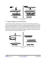
Page 5: ...63 mW transmit power levels Transparent ARQ protocol with data buffering ensures data integrity Selectable RF data rates of 38 4 115 2 200 and 500 kb s Analog and digital I O simplifies wireless sensing Auto reporting I O mode simplifies applica tion development 1 1 Why Spread Spectrum A radio channel can be very hostile corrupted by noise path loss and interfering transmissions from other radios ...

Page 6: ...equence spread spectrum is produced by multiplying the transmitted data stream by a much faster noise like repeating pattern The ratio by which this modulating pattern exceeds the bit rate of the base band data is called the processing gain and is equal to the amount of rejection the system affords against narrow band interference from multipath and jammers Transmitting the data signal as usual bu...

Page 7: ...nge the frequency at which they transmit In order for the other radios in the network to receive the transmission they must be listening to the frequency on which the current transmission is being sent To do this all the radios in the network must be synchronized to the same hopping pattern In point to point or point to multipoint networks one radio module is designated as the base All other radio...

Page 8: ...AuthMode parameter is set to 1 a remote s address must be listed in Parameter Bank 7 before it will be allowed to register with the base This is referred to as base authentication Bank 7 must be preloaded with the addresses of the authorized remotes before using base authentication If a remote whose MAC address is not in Bank 7 attempts to join the network the base radio will deny the registration...

Page 9: ...tion parameters control when a DNT2400 radio will send the data in its transmit buffer The MinPacketLength parameter sets the minimum number of bytes that must be present in the transmit buffer to trigger a transmission The TxTimeout parameter sets the maximum time data in the transmit buffer will be held before transmitting it even if the number of data bytes is less than MinPacketLength The defa...

Page 10: ... base transmitter power setting which is periodically transmitted by the base The remote automatic transmit power adjustment is enabled by default but can be disabled if so desired Refer to Section 4 2 1 for details 2 7 Network Configurations The DNT2400 supports three network configurations point to point point to multipoint and peer to peer In a point to point network one radio is set up as the ...

Page 11: ...a point to point network When the base receives the transmission it will format the data to its host according to its formatting configuration A remote running in transparent mode in a point to multipoint network can have the MinPacketLength and TxTimeout parameters set to their default values to reduce latency or above their default values to re duce the volume of small packet transmissions 2 7 3...

Page 12: ...s of data and or packets sent at random times from a large number of remotes Time Division Multiple Access TDMA provides a scheduled time slot for each remote to transmit on each hop The default DNT2400 access mode is TDMA dynamic mode Access Mode Description Max Number of Remotes 0 Polling unlimited 1 CSMA unlimited 2 TDMA dynamic slots up to 16 3 TDMA fixed slots up to 16 4 TDMA with PTT up to 1...

Page 13: ... channel will increase It will continue to increase each subsequent time the channel is busy until the channel is finally found idle This is the classic CSMA technique that handles the situation where a number of remotes hold data to send at the same time The CSMA_ Predelay parameter controls the maximum time that a remote will wait before first listening to see if the channel is clear for a trans...

Page 14: ...RemoteSlotSize are computed automatically by the DNT2400 network in this mode The user must set the number of slots using the MaxSlots parameter The base radio will allocate remote slot sizes as if MaxSlots number of remotes are linked with the base even when fewer remotes are actually linked In this mode the remote slot sizes are constant TDMA with PTT mode 4 supports remotes with a push to talk ...

Page 15: ...s the DNT Throughput Calculator utility pro gram DNTCalc exe This program is on the development kit CD Enabling encryption security adds additional bytes to the data to be sent but the Calculator has a mode to take this into account 2 10 2 Polling Throughput In polling mode the application sends data from the base to a specific remote which causes the remote and or its host to send data back to th...

Page 16: ...ill be the first remote to transmit on the next hop or that it will be able to transmit on the next hop at all To allow multiple remotes a chance to transmit on the same hop the HopDuration parameter must be set long enough to support the BaseSlotSize plus the number of remotes to transmit per hop multiplied by the CSMA_ RemtSlotSize plus the number of remotes to transmit per hop multiplied by the...

Page 17: ... this is why CSMA networks are best used when there are a large number of nodes that send data infrequently The other factor impacting latency is retries This impact is not unique to frequency hopping radios but is common among all wireless technologies A radio only transmits data once per hop It needs to wait until the next hop to see if the transmission was received at the destination If not the...

Page 18: ...lt as inputs to the Calculator program to determine minimum valid HopDuration CSMA contention mode 1 the same procedure as for polling is used except that the CSMA_ RemtSlotSize typically should be set at three times the maximum number of data bytes for point to multipoint networks The default values for CSMA pre delay and back off are assumed TDMA dynamic mode 2 this is the DNT2400 s default oper...

Page 19: ...fault maximum operating range unless links of more than 20 miles are planned 3 Set the HopDuration parameter and then read it back If the HopDuration parameter readout is different than the value set the firmware detected an invalid configuration and is overriding it 2 11 Serial Port Operation DNT2400 networks are often used for wireless communication of serial data The DNT2400 supports serial bau...

Page 20: ... not exceeded It is strongly recommended that the DNT2400 host use hardware flow control in applications where the transmit buffer can become full The host must send no more than 32 additional bytes to the DNT2400 when the DNT2400 de asserts the host s CTS line In turn the DNT2400 will send no more than one byte following the host de asserting its RTS line Three wire serial port operation is allow...

Page 21: ...mote has received an acknowledgement for its I O report a WakeResponseTime timer is started before the remote goes back to sleep This allows the base host time to send a mes sage to the remote Note that the only notification that the base host application has that a remote is awake is its report packet In order to send it data the base host must ensure that the message is transmitted and received ...

Page 22: ...V RADIO_TXD Normal operation Hi Z RADIO_RXD Normal operation 0 V Table 2 12 1 Note that the ACT pin may be used by a local host to detect when a sleeping remote is awake The behavior of the GPIOs during sleep is governed by the GPIO_ SleepMode GPIO_SleepDir and GPIO_SleepState configuration registers Refer to the register definitions in Section 4 2 2 13 Encryption The DNT2400 supports 128 bit AES ...

Page 23: ...chronize a group of co located base stations after a period of time 5 An optional wide pulse of 1 to 2 ms triggers a hopping pattern reset Note a wide pulse can only be used in ETSI applications It is not allowed under FCC and Canadian IC regulations The benefit provided by the wide pulse is to keep co located networks from ever be ing on the same frequency at the same time When the wide pulse is ...

Page 24: ...FHSS transceiver and a low current 32 bit microcontroller The DNT2400 operates in the 2 4 GHz ISM band The module includes nine frequency subbands and 37 total frequency channels to support the various 2 4 GHz frequency allocations used throughout the world The DNT2400 has three selectable RF output power levels 1 10 and 63 mW Also there are four selectable RF transmission rates 38 4 115 2 200 and...

Page 25: ...A 16 CSMA unlimited ADC Input Range 0 3 3 V ADC Input Resolution 10 bits Signal Source Impedance for ADC Reading 10 KΩ PWM DAC Output Range 0 3 3 V PWM DAC Output Resolution 8 bits PWM Output Period 20 µs Primary Serial Port Baud Rates 1 2 2 4 4 8 9 6 19 2 28 8 38 4 57 6 76 8 115 2 230 4 460 8 kb s Diagnostic Serial Port Baud Rate 38 4 kb s Digital I O Logic Low Input Level 0 5 0 8 V Logic High In...

Page 26: ... filter Filter is 1st order 159 Hz 3 dB BW 11 SLEEP DTR I Default functionality is active high module sleep input active low DTR When switched low after sleep the module executes a power on reset Usually connected to host DTR 12 ADC2 I 10 bit ADC input 0 Full scale reading is referenced to the ADC_REF input 13 ADC1 I 10 bit ADC input 1 Full scale reading is referenced to the ADC_REF input 14 ADC0 ...

Page 27: ...cale and or ratiometric ADC readings etc Current drain on this output should be no greater than 5 mA 35 RSVD Reserved pad Leave unconnected 36 RSVD Reserved pad Leave unconnected 37 RSVD Reserved pad Leave unconnected 38 RSVD Reserved pad Leave unconnected 39 RESET I Active low module hardware reset 40 RSVD Reserved pad Leave unconnected 41 GND RF ground DNT2400C only Connect to the host circuit b...

Page 28: ...oard should be implemented as a 50 ohm stripline Referring to Figure 3 3 1 the width of this stripline depends on the thickness of the circuit board between the stripline and the groundplane For FR 4 type circuit board materials dielectric con stant of 4 7 the width of the stripline is equal to 1 75 times the thickness of the circuit board Note that other circuit board traces should be spaced away...

Page 29: ...r the DNT2400 Data Sheet for DNT2400P connector details DNT2400 enclosures must be made of plastics or other materials with low RF attenuation to avoid com promising antenna performance where antennas are internal to the enclosure Metal enclosures are not suitable for use with internal antennas as they will block antenna radiation and reception Outdoor enclo sures must be water tight such as a NEM...

Page 30: ... cause interference and 2 this device must accept any interference including interference that may cause undesired operation of the device Canadian ICES 003 This digital apparatus does not exceed the Class B limits for radio noise emissions from digital apparatus as set out in the radio interference regulations of Industry Canada Le present appareil numerique n emet pas de bruits radioelectriques ...

Page 31: ...s vary in size and number depending on the type of message and whether it is a message sent from the host or is a reply from the radio see Table 4 1 2 1 below Messages that are generated on the serial interface by the user are referred to as host messages Messages that are generated by the radio are referred to as reply messages For many message types there is a reply message that corresponds to a...

Page 32: ...dio Addr RSSI Reg Bank Span Val 0x0A GetRemoteRegister from Host Addr Reg Bank Span 0x1A GetRemoteRegisterReply from Radio If command successful TxStatus Addr RSSI Reg Bank Span Val If command failed TxStatus Addr 0x0B SetRemoteRegister from Host Addr Reg Bank Span Val 0x1B SetRemoteRegisterReply from Radio TxStatus Addr RSSI 0x2C JoinRequest from Radio Addr 3 Reserved Bytes 0x0C JoinReply from Ho...

Page 33: ... Additional fields E0 Protocol error invalid message type none E1 Protocol error invalid argument none E2 Protocol error general error none E3 Protocol error parser timeout none E4 Protocol error register is read only none E8 UART receive buffer overflow none E9 UART receive overrun none EA UART framing error none Range Range measurement of joining radio 1 byte Each count equals 0 29 miles BootSel...

Page 34: ...ration registers supported by the DNT2400 are described below Registers are sorted into banks according to similar functions Default register values are in bold All changes to parameters are temporary and will not persist through power cycling until 0x01 has been written to the MermorySave parameter in Bank FF Writing 0x00 to the MemorySave parameter will reload the factory default values which al...

Page 35: ...will start if a base or join if a remote A value of 0xFF instructs a remote to operate in promiscuous mode and join any network it finds if set for a base this will select the default network ID of 0x00 The network ID also sets the base frequency at which the hopping pattern starts as illustrated by the following equation FrequencyIndex n HoppingPattern n NetworkID mod 32 This allows the user to c...

Page 36: ...IO5 0 0 V output default 1 3 3 V output 2 hop by hop toggle between 0 and 3 3 V UserTag this is a user definable field intended for use as a location description or other identifying tag such as a friendly name RegDenialDelay when a remote has been removed from a network through a RemoteLeave the Reg DenialDelay parameter sets the length of time the remote will wait before considering that network...

Page 37: ...hannels 1 2 and 13 0xFF 15 to 37 Auto Autoscan for remote to match base AccessMode this sets the channel access mode that remotes will use to communicate with the base Access Mode Description Max of Remotes Remote Slot Size 0 Polling unlimited manual 1 CSMA unlimited manual 2 default TDMA dynamic slots up to 16 automatic 3 TDMA fixed slots up to 16 automatic 4 TDMA with PTT up to 16 automatic unli...

Page 38: ...htly from the overall slot time available to remotes for sending data Note that the free space round trip propagation delay for one mile is 10 72 µs Each incre ment of MaxPropDelay thus corresponds to a maximum radius from the remote to the base of 0 29 mi 0 46 km The default setting provides enough time to handle remotes up to 20 miles away It is recom mended to use the default setting unless a p...

Page 39: ...fff fixed value 02 03 Reserved R 1 0 255 reserved 02 04 CurrNwkID R 1 0 255 as set 02 05 CurrRF_DataRate R 1 0 4 as set 02 06 CurrFreqBand R 1 0 1 as set 02 07 LinkStatus R 1 0 1 current status 02 08 RemoteSlotSize R 1 0 243 as set 02 09 TDMA_NumSlots R 1 0 16 as set 02 0A Reserved R 1 0 255 reserved 02 0B TDMA_CurrSlot R 1 0 16 current slot 02 0C HardwareVersion R 1 0 255 0x00 DNT2400 rev A 02 0D...

Page 40: ...des where this number is not applicable it is read as 0xFF HardwareVersion returns an identifier indicating the type of radio A value of 0x41 is defined for the DNT2400 Rev A hardware FirmwareVersion returns the firmware version of the radio in 2 digit BCD format FirmwareBuildNum returns the firmware build number in binary format SuperframeCount returns the current superframe count The count incre...

Page 41: ...top bits 0x02 Reserved 0x03 Reserved 0x04 Even parity 8 data bits 1 stop bit 0x05 Even parity 8 data bits 2 stop bits 0x06 Odd parity 8 data bits 1 stop bit 0x07 Odd parity 8 data bits 2 stop bits Note that 8 bit data with no parity is capable of carrying 7 bit data with parity for compatibility without loss of generality for legacy applications that may require it SerialControls this parameter af...

Page 42: ... is a bitmask that selects various options for the protocol mode The default is 0x05 bits 7 3 Reserved bit 2 Enable output of TxReply packets bit 1 Reserved bit 0 Enable output of Announce packets AnnounceOptions this is a bitmask that enables disables different types of Announce packets bit 7 3 Reserved bit 2 Enable bit for Announce types E0 EA error notification bit 1 Enable bit for Announce typ...

Page 43: ...0 2 read only returns the current 10 bit ADC reading for the selected register See the discussion of the ADC_SampleIntvl parameter below EventFlags used with the automatic I O reporting feature this parameter indicates which I O events have been triggered since the last report message bits 15 8 Reserved bit 7 ADC2 high low threshold excursion bit 6 ADC1 high low threshold excursion bit 5 ADC0 high...

Page 44: ...ting of GPIOs to the designated direction and state whenever a device is asleep GPIO_SleepDir when GPIO_SleepMode is enabled this parameter functions as a secondary GPIO_Dir to set the direction of the GPIOs during a device s sleep period This enables the user to provide alternate configurations during sleep that will help minimize current consumption Bits 0 5 correspond to GPIO0 GPIO5 Set a GPIO_...

Page 45: ... send an EVENT message to its base containing the entire current values of the I O Register Bank from GPIO0 up to and including the EventFlags but not the PWM settings which are output only bit 7 ADC2 high low thresholds bit 6 ADC1 high low thresholds bit 5 ADC0 high low thresholds bit 4 Periodic report timer bit 3 GPIO3 edge bit 2 GPIO2 edge bit 1 GPIO1 edge bit 0 GPIO0 edge I O reporting is supp...

Page 46: ...ll cause the remotes to say awake Writing 0x00 to this location causes the remotes to resume sleeping in 10 sec onds Writing 0x02 to this location causes the remotes to resume sleeping immediately subject to their configuration MemorySave writing a 0x00 to this location clears all registers back to factory defaults Writing 0x01 to this location commits the current register settings to EEPROM When ...

Page 47: ...moteRegister commands The command to set the IO_ReportInterval to 10 seconds is 0xFB 0x0B 0x0B 0x56 0x34 0x12 0x1A 0x06 0x04 0xE8 0x03 0x00 0x00 The IO_ReportInterval parameter starts in location 0x1A of bank 0x06 The report interval is set in 10 ms units so a 10 second report interval is 1000 units or 0x000003E8 Little Endian format E8 03 00 00 The IO_ReportInterval parameter is updated and SetRe...

Page 48: ... RJ 11 DB 9F cable assembly two A B USB cables One DNT2400DK documentation and software CD 5 2 Additional Items Needed To operate the kit the following additional items are needed One PC with Microsoft Windows XP or Vista Operating System The PC must be equipped with a USB port or a serial port capable of operation at 9 6 kb s 5 3 Developer s Kit Operational Notes DNT2400DK kits are preconfigured ...

Page 49: ...er as needed for longer range operation Note that setting the RF power to a high level when doing testing at 2 m can overload the DNT2400P receiver and cause erratic operation See Section 5 3 5 5 Developer s Kit Hardware Assembly Observe ESD precautions when handling the kit circuit boards The components that make up a devel opment board are shown in Figure 5 5 1 and are shipped with the DNT2400P ...

Page 50: ...by RF Monolithics Inc E mail tech_sup rfm com DNT2400 08 18 09 As shown in Figure 5 5 3 there is a jumper on pins J14 This jumper can be removed and a current meter connected across J14 to measure just the DNT2400 s current consumption during operation Figure 5 5 3 ...

Page 51: ...switches operation from the RJ 45 connector The USB interface is based on an FT232RL serial to USB converter IC manufactured by FTDI The FT232RL driver files are located in the i386 and AMD64 folders on the kit CD and the latest version of the drivers can downloaded from the FTDI website www ftdichip com The drivers create a virtual COM port on the PC Power the Base using one of the supplied wall ...

Page 52: ... preferred PC interface is a serial port capable of operating at 9 6 kb s or faster As discussed above the USB interface can also be used Connect the Base to the PC and power up the Base and the Remote development boards with the supplied wall plug power supplies The DNT Demo utility program is located in the PC Programs folder The DNT Demo requires no installation and can be simply copied to the ...

Page 53: ... either the hardware port or the USB virtual serial port Then click OK to activate the serial connection Figure 5 6 1 2 At this point the Demo will collect data from the Base filling in data in the Local Radio column on the Demo window as shown in Figure 5 6 1 3 The Status Window should also show that the Remote has joined the Base Click on the drop down box at the top of the Radio 1 column and se...

Page 54: ...To perform serial data loop back testing with the kit move the two jumpers on the Remote board labeled Ext_TX and Ext_RX to connect the center and right header pins This disconnects the module s TX and RX pins from the USB and RS 232C circuits Use a banana clip or other short jumper to connect together the two pins on the header labeled J11 Ext_MICRO See Figure 5 6 1 5 Attempting loop back testing...

Page 55: ...The E mail address is tech_sup rfm com 5 6 2 Serial Communication and Radio Configuration Connect PCs to both the Base and the Remote for serial communication testing Click the Stop button under the Refresh Delay label on the I O Tools tab and move to the Transmit Tools tab as shown in Figure 5 6 2 1 Figure 5 6 2 1 Pressing the Transmit button on this screen sends the message in the Data to Transm...

Page 56: ...orresponding to Bank 7 Figure 5 6 2 2 The Transceiver Setup Tab is shown in Figure 5 6 2 2 and corresponds to Bank 0 The current values of each Bank 0 parameter are displayed and can be updated by selecting from the drop down menus or entering data from the keyboard and then pressing the Apply Changes button Note that data is displayed and entered in Big Endian order The Demo automatically reorder...

Page 57: ...Bank 1 holds configuration parameters for the base only except for ARQ_Mode which applies to both the base and the remotes Figure 5 6 2 4 Figure 5 6 2 4 shows the Status tab contents corresponding to Bank 2 Note the Status tab contains read only parameters Figure 5 6 2 5 Figure 5 6 2 5 shows the Serial tab contents corresponding to Bank 3 The values shown are the defaults for serial port operation...

Page 58: ...s corresponding to Bank 4 Transparent data serial com munication is currently chosen Figure 5 6 2 7 Figure 5 6 2 7 shows the I O Peripherals tab contents corresponding to Bank 5 GPIO ports 1 2 3 4 and 5 are logic low GPIO port 0 is logic high The 10 bit ADC input readings and PWM output settings are given in Big Endian byte order Event flags are presented on the right side of the window ...

Page 59: ...are config ured as inputs event interrupts can be set for them with check boxes The type of interrupt trigger is selected from the drop down boxes to the right of the check boxes GPIO alternate function periodic I O reporting reporting interval and enable disable sleep I O states can also be specified under this tab Figure 5 6 2 9 Figure 5 6 2 9 shows the second I O Setup tab contents correspondin...

Page 60: ...0 Page 60 of 82 2009 by RF Monolithics Inc E mail tech_sup rfm com DNT2400 08 18 09 Figure 5 6 2 10 Figure 5 6 2 10 shows the Auth List tab where the MAC addresses of the remotes authorized to join the network in AuthMode 1 are input into Bank 7 ...

Page 61: ...gles the SLEEP DTR input to the DNT2400 on and off This allows the DNT2400 to be reset F2 toggles the RTS input to the DNT2400 on and off providing manual flow control F6 toggles test transmissions on and off The test message is This is a test DNTWizard also includes the ability to log messages to and from the DNT2400 This feature is especially useful in confirming the format of protocol command a...

Page 62: ...Set the baud rate to 9600 9 6 kb s Set the CommPort to match the serial port connected to the Base either the hardware port or the USB virtual serial port Then click OK to activate the serial connection Figure 5 7 2 At this point the Wizard will collect data from the Base filling in data under Current Settings as shown in Figure 5 7 3 The Status Window should also show that the Remote has joined t...

Page 63: ...p rfm com DNT2400 08 18 09 There are three tabs on the DNTWizard main window Receive Data Transmit Data and Wincom Figure 5 7 4 Received messages are displayed in the Receive Data tab along with the MAC address of the sender and the RSSI signal strength of the received message in dBm See Figure 5 7 4 ...

Page 64: ...own box Note that the MAC address a remote uses for the base is always 0x000000 If the Transmit Interval is set to 0 the message is sent once each time the Transmit button is clicked When the Transmit Interval is set to an integer greater than zero the message will sent at the beginning of each interval until the Stop button was Transmit button is clicked The status of each transmission is shown b...

Page 65: ... Monolithics Inc E mail tech_sup rfm com DNT2400 08 18 09 Figure 5 7 6 As shown in Figure 5 7 6 the Wincom tab provides the basic functionality of a serial terminal program Messages typed in are sent and messages received are appended to the bottom of the on screen text ...

Page 66: ...ed on the first six tabs corresponds to configuration register Banks 0 through 5 as discussed in Section 4 2 above with the data on the next two tabs corresponding to configuration register Bank 6 and data on the last tab corresponding to Bank 7 Figure 5 7 7 The Configuration window in the DNTWizard is identical the Configuration window in the DNT Demo See Figures 5 6 2 2 through 5 6 2 10 for Conf...

Page 67: ...View and Tools menus are shown in Figure 5 7 8 Figure 5 7 8 The Tools menu contains two very useful items Packet Builder opens the window shown in Figure 5 7 9 On the left the Packet Type drop down box provides a selection of all packet types used in the DNT2400 protocol On the right the reply packet types are presented Figure 5 7 9 Figure 5 7 10 ...

Page 68: ...ecv Data FB 08 13 00 03 04 30 00 00 07 Get Register Reply Sent Data FB 04 03 00 04 08 Get Register Recv Data FB 0C 13 00 04 08 00 05 00 01 07 00 02 00 Get Register Reply Sent Data FB 04 03 00 05 12 Get Register Recv Data FB 16 13 00 05 12 01 00 00 00 00 00 19 02 78 02 1D 02 00 00 00 00 00 00 Get Register Reply Sent Data FB 04 03 00 06 1E Get Register Recv Data FB 22 13 00 06 1E 00 00 00 01 00 00 C...

Page 69: ... D4 illuminates on the base when one or more remotes are registered to it unless the base has been configured to assert DCD on power up In this case it will be on as long as the dev board is powered Green Activity LED D1 illuminates when transmitting or receiving RF data Red Receive LED D3 illuminates when sending received data through the serial port to the PC Green Trans mit LED D2 illuminates w...

Page 70: ... possi ble to connect directly to RADIO_TXD and RADIO_RXD by moving the jumpers over In this case J11 1 is the input for transmitted data and J11 2 is the output for received data Note this a 3 V logic interface Placing a shorting plug on jumper pin set J6 allows the DNT2400P to be powered up in boot loader mode This is used for factory code loads and functional testing The DNT2400 has its own boo...

Page 71: ... silkscreen The wiper of pot R10 drives the input of ADC1 Clockwise rotation of the pot wiper increases the voltage Thermistor RT1 is part of a voltage divider that drives ADC0 LED D5 illumi nates when GPIO1 is set as a logic high output LED D10 illuminates when GPIO3 is set as a logic high The DNT2400P interface board includes a 5 V regulator to regulate the input from the 9 V wall plug power sup...

Page 72: ...emo program installed 3 Place the transceiver interface boards at least 6 feet two meters apart 4 Start the DNT Demo program 5 Click the Connect button on the Demo window This will open a serial port setup dialog box Set the baud rate to 9600 9 6 kb s and select the COM port where the Base is connected 6 At this point the Demo will collect data from the Base filling in data in the Local Radio colu...

Page 73: ... that RTS is asserted to enable re ceive character flow Make sure the RF transmit power is not on a high settings if the nodes are close together Range is extremely limited this is usually a sign of a poor antenna connection or the wrong antenna Check that the antenna is firmly connected If possible remove any obstructions near the antenna Transmitting terminal flashes drops CTS occasionally this ...

Page 74: ...he fourth character is a character Each time stamp count is 100 µs The time stamp rolls over to 0x000 after count 0xCE5 The content of the seven data values are detailed below ASCII representations of the hexadecimal value of each byte are output separated by space characters Byte 0 current channel 0 to 36 Byte 1 same data as FSTAT 1 except no activity is 0x30 Byte 2 RSSI_Last RSSI of last RF pack...

Page 75: ...he time stamp is 0x896 Byte 0 0x21 indicates the channel of operation is 33 decimal Byte 1 0x01 is the same status data as FSTAT data above In this case DataTx activity only Byte 2 0xDA is the last RSSI value 38 dBm Byte 3 0x98 is the RSSI idle value 100 dBm Byte 4 0x00 is the range delay estimate remote only The remote is very close to the base Byte 5 0x01 provides the serial port status HOST_CTS...

Page 76: ...p rfm com DNT2400 08 18 09 8 0 Appendices 8 1 Ordering Information DNT2400C transceiver module for solder pad mounting DNT2400P transceiver module for pin socket mounting 8 2 Technical Support For DNT2400 technical support call RFM at 678 684 2000 between the hours of 8 30 AM and 5 30 PM Eastern Time ...

Page 77: ...Inc E mail tech_sup rfm com DNT2400 Integration Guide 08 18 09 8 3 DNT2400 Mechanical Specifications D N T 2 4 0 0 C O u t l i n e a n d M o u n t i n g D i m e n s i o n s D i m e n s i o n s i n i n c h e s 2 0 1 0 1 2 6 0 0 5 9 5 0 1 8 0 0 0 4 0 0 0 4 0 0 1 0 0 1 4 0 Figure 8 3 1 ...

Page 78: ... by RF Monolithics Inc E mail tech_sup rfm com DNT2400 Integration Guide 08 18 09 D N T 2 4 0 0 P O u t l i n e a n d M o u n t i n g D i m e n s i o n s D i m e n s i o n s i n i n c h e s 2 0 5 0 0 2 8 5 0 0 4 0 0 1 0 0 0 3 3 3 0 0 5 0 1 3 6 0 1 4 0 Figure 8 3 2 ...

Page 79: ... 9 4 8 3 2 0 5 0 8 0 1 2 5 D N T 2 4 0 0 P I n t e r f a c e C o n n e c t o r P C B L a y o u t D e t a i l 0 1 2 5 C o n n e c t o r s a r e F C I E l e c t r o n i c s 7 5 9 1 5 4 2 0 L F o r e q u i v a l e n t D i m e n s i o n s i n i n c h e s a n d m m 1 2 6 M i n i m u m p l a t e d P C B h o l e d i a m e t e r 0 0 3 0 7 5 Figure 8 3 3 ...

Page 80: ...2400 Development Board Schematic 0 1 2 3 334 5 6 7 6 89 9 3 0 1 2 3 334 5 6 7 6 89 9 3 0 1 2 3 334 5 6 7 6 89 9 3 0 110 2 1 110 3 110 4 5 4 5 5 4 5 5 4 5 5 5 5 3 4 5 3 4 5 3 3 5 4 4 3 4 4 4 5 5 4 5 5 5 5 5 3 3 5 4 4 3 4 3 3 5 5 3 3 4 3 7 7 5 5 5 5 54 54 4 5 3 3 4 4 6 7 6 7 4 5 4 5 4 3 5 4 3 5 4 4 4 5 3 4 3 5 3 4 4 4 4 4 5 4 3 4 4 54 54 6 7 8 5 6 7 8 5 ...

Page 81: ...rfm com DNT2400 Integration Guide 08 18 09 0 1 2 3 334 5 A 6 7 6 89 9 3 0 1 2 3 334 5 A 6 7 6 89 9 3 0 1 2 3 334 5 A 6 7 6 89 9 3 9 2 2 2 0 110 2 1 110 3 110 1 4 4 4 4 4 7B 3 3 5 5 5 5 3 3 3 3 4 3 4 4 C C 4 3 4 3 5 5 5 5 7 7 5 5 4 4 5 5 5 5 4 3 5 4 6 4 6 3 5 6 3 5 6 4 4 4 4 3 3 3 3 4 3 5 3 3 5 5 4 4 5 5 ...

Page 82: ...re not de signed or by causes external to the goods such as but not limited to power failure No suit or action shall be brought against Seller more than twelve 12 months after the related cause of action has oc curred Buyer has not relied and shall not rely on any oral representation regarding the goods sold here under and any oral representation shall not bind Seller and shall not be a part of an...

Reviews: