background image

RH MARINE NETHERLANDS B.V. 

Sluisjesdijk 155 
P.O. Box 5054 
NL-3008 AB Rotterdam 
The Netherlands 

T +31 10 487 19 11 
F +31 10 487 17 02 
info@rhmarine.com 
www.rhmarine.com 


Reference number: 4111A-RADAR4600-GBD-R1.1 


27 February 2018 
Page 1 of 149 


Rhodium RADAR 4600 

User Manual 


Date 

27 February 2018 

Reference 

4111A-RADAR4600-GBD-R1.1 


Project Name 

Project number 

Summary of Contents for Rhodium RADAR 4600

Page 1: ...m The Netherlands T 31 10 487 19 11 F 31 10 487 17 02 info rhmarine com www rhmarine com Reference number 4111A RADAR4600 GBD R1 1 27 February 2018 Page 1 of 149 Rhodium RADAR 4600 User Manual Date 27 February 2018 Reference 4111A RADAR4600 GBD R1 1 Project Name Project number ...

Page 2: ...Page 2 of 149 Rhodium Bridge Product Line PPM Main title Date User Manual RADAR4600 27 February 2018 Subtitle Reference number RADAR 4600 4111A RADAR4600 GBD R1 1 Version R1 1 Total number of pages 149 Registration code 4111A RADAR4600 GBD Rx x x Author PPM Quality control PPM ...

Page 3: ...2 Upper left corner 18 2 2 1 Lower left corner 18 2 2 2 Upper right corner 19 2 2 3 Radar Control group 19 2 2 4 Lower right corner 19 2 2 5 Upper centre line Range selection 20 2 2 6 Menu blocks with info pages and function select 20 2 2 7 Rou 20 2 2 8 Route display and information 21 2 2 9 Colours of screen contents 21 2 2 10 Different kinds and states of selector buttons 22 2 3 Radar image 24 2...

Page 4: ...4 6 Select Motion modes 45 3 4 7 Set Own Ship position 45 3 4 8 Ships position in TM Mode 45 3 4 9 Course Speed through water or over ground 46 3 4 10 Manual Speed plus Set and Drift 46 3 4 10 1 Manual Speed 46 3 4 10 2 Set and Drift corrections 46 3 4 10 3 Examples of displaying Stabilizing Modes 47 3 4 11 Target trails Afterglow as track of past positions 49 3 4 12 Imitated target trail in TM 51...

Page 5: ...17 Affect between monitored targets by varying settings 82 3 6 18 Performance specification for tracked and for AIS targets 83 3 6 19 Multi radar functionality Optional 85 3 6 20 Working with multi radar display optional 88 3 6 20 1 Switching between radar layers 88 3 6 20 2 Settings for tracked target association 91 3 7 Alarms and warnings 92 3 7 1 General 92 3 7 2 Alert priorities 92 3 7 3 Alert...

Page 6: ...etection ranges subject to regulations 121 7 6 Target discrimination in relation to beamwidth 122 7 7 Target discrimination in relation to Pulselength 122 7 8 Blind and shadowed target areas 122 7 8 1 Blind or shadowed areas 123 7 9 False targets 123 7 10 Target enhancer 125 7 10 1 RACON targets 125 7 10 2 SART targets 125 7 10 3 Active Radar Target Enhancer RTE 126 7 10 4 Corner reflectors as pas...

Page 7: ... manual RH Marine is not liable for earthquake lightning fire action by third party other accident customer s unintended error abuse and damage caused by the use under other abnormal condition RH Marine is not liable for damage of accompaniment change loss of memorized content loss of business profit stop of business arisen from use or failure of our product If the stored data is changed or lost i...

Page 8: ...utside the hazard zone around an antenna or open waveguide radiating power Refer to the table below for hazard zones When it is necessary to work on the Scanner Unit make sure that RADAR is switched OFF and that both the Mains Isolator and the Scanner Control Unit are turned to the OFF position Never look directly into an open waveguide Radar and other forms of RF radiation can cause Cardiac Pacem...

Page 9: ...AR4600 GBD R1 1 Date 27 February 2018 Page 9 of 149 WARNINGS REGARDING SYSTEM EQUIPMENT CAUTION Electrostatic Sensitive Devices ESSDs This equipment contains ESSDs Take care not to damage these devices by discharge of electrostatic voltages ...

Page 10: ...document may be photocopied reproduced of translated into another language without prior written consent of RH Marine Updates In the table below the corrections are recorded of those parts that have changed since the previous version Version Date Change Correction Reason 1 0 2010 07 First release 1 1 2018 02 Changed to RH Marine layout Imtech references changed ...

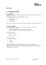
Page 11: ...00 is a modular and scalable PC based radar system built from 3 main building blocks Transceiver unit X or S band Radar server signal processing unit 1 required for each transceiver Radar client display unit display sizes meet CAT1 or CAT2 requirements A radar server consists of Radar server software PC Radar interface card A radar client consists of Radar client software PC TFT display Track ball...

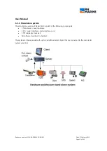
Page 12: ...stand alone version of Radar 4600 consists of the following components 1 Transceiver radar antenna 1 PC serial interface radar interface card 1 TFT display track ball All software described in chapter 3 The system can be expanded with up to 9 additional radar clients that are connected to the main radar system via a LAN ...

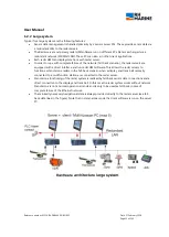
Page 13: ...r servers are equipped with a direct interface and run radar HMI software This allows the radar servers to function as stand alone radars in the fall back scenario when a display and track ball normally connected to a multifunction station are connected to the radar server Stand alone functioning of the radar system is realized by fall back sensor data connections and a direct connection to the di...

Page 14: ...ta Validation of NMEA inputs Data selection automatic switch over in case multiple sensors provide the same type of data e g 2x Gyro compass or GPS and bottom track system 1 3 3 Infrastructure management The infrastructure tasks are primarily responsible for ensuring monitoring the integrity of the other software tasks Application Manager software runs on each PC while each system has 1 stand alon...

Page 15: ...sed application the other equipment is intended for protected application 1 4 2 Transceivers ancillaries The system supports the following transceivers antennas ancillary units Sperry Sperry Marine VisionMaster FT Bridgemaster E legacy RADAR scanners X Band and S Band 1 4 3 PC and Display types Different Hatteland PCs and different TFT displays with 23 16 9 are available In either case they comply...

Page 16: ...IS data from an AIS receiver All sensors must comply with IEC standards and IMO resolutions 1 5 1 Serial interface The system supports the following NMEA 0183 IEC61162 serial messages 1 5 2 VDR output The output to a VDR VGA or DVI I or IEC61162 450 is available In case of multiple radar clients the screen image from a client or multiple is captured and sent to the VDR output of the bridge system ...

Page 17: ...with selector functions for radar ranges and for range rings Upper right corner with function buttons for presentation modes and with cells for information of cursor position and CPA TCPA limits Lower right corner with EBL and VRM functions Menu blocks as columns on right side of radar image for activating of variable adjustment functions and of different information pages Upper left corner centre...

Page 18: ... versions to yellow to signal a caution state If no or invalid data are available the indication of data kind changes to red and only some dashes are shown instead of data values 2 2 1 Lower left corner This part contents settings and adjustment functions for the radar transceiver to get an optimum of target indication Activated functions are shown in blue colour Interference rejection Target enha...

Page 19: ...TT AIS Selector buttons to open lists of alarms separate selected target and separate selected AIS target 2 2 3 Radar Control group Selector buttons for presentation mode of radar image and for target information N UP or C UP or H UP STAB or H UP T BRG Scale or R BRG Scale TM or RM SEL TGT Select up to 2 single AIS or Tracked targets CENT OS back to Centre RESET Manual OS position reset only in TM...

Page 20: ...c lines Clicking the RNG bar changes the line to single buttons with adjacent ranges to select direct one of them 2 2 6 Menu blocks with info pages and function select Clicking one of the three topside selector buttons opens a regarding list of targets with alarming state or one of two lists with separate selected radar or AIS targets Beside example shows data of two selected tracked targets Targe...

Page 21: ...more visible colour discrimination Presentation of NIGHT mode is similar but much more dimmed The background of radar image is blue black in later versions Radar targets are yellow with different steps of brightness depending on strength of received signal Other parts of screen are more or less in dark grey or grey blue Data which are computed by the RADAR 4600 Radar System with regarding notes ar...

Page 22: ...d state Selector button blue shadowed for dedicated cursor function in activated state Selector button not activated The lightened little corner upside right indicates that alternatives are available by pop up Available alternatives the blue button is the activated one To change the needed grey button must be clicked Clicking pops up the alternatives Selected mode for Vector Length The arrow butto...

Page 23: ...e options selectable Clicking an arrow widens the menu showing the options Padlock icons are used in connection with special EBL VRM functions see chapt 3 5 4 2 Differentiation between squared and circled marking boxes If squared boxes are shown one some or all options can be activated resp deactivated If circled boxes are shown only one option can be activated and is shown in black If another box...

Page 24: ...ly and then change depending on actual course movements In North Up N UP mode the lines are drawn at the current compass heading When own ship is off centred the heading line bearing is automatically adjusted so that the scale is always referenced correctly see example beside For further information on how the presentation mode affects own ship s heading line see chapt 3 4 1 The position of the he...

Page 25: ... bearings made from OS are bearings related to ships heading line as zero degree The True bearing scale acts as gyrocompass repeater The heading line always is directed onto the actual steered compass course To change scale mode click button R BRG Scale resp T BRG Scale The popup window shows the alternatives Click the respective grey coloured button to change the mode True bearings scale is activ...

Page 26: ...IS target Off centre Cursor Cursor ready to deactivate AIS target Off centre Cursor Area not allowed to set Cursor activated in map function to set polygon points 2 3 6 Own ship indication The Own Ship position is shown in different ways depending on selected radar range and activated navigation functions Own ship minimized symbol consists of a heading line and a beam line which intersects at the ...

Page 27: ...d Target with position points of past track with user defined intervals 18 Tracked Target calculated as dangerous is shown in red and flashing for alarming An acquired AIS target with headline showing the direction of COG or CTW The length represents the distance which will be travelled during the user specified time The target may have a turn indicator at the end of heading line as a small line p...

Page 28: ...s in a layered manner one above another Radar images in a higher layer are drawn over radar images in a lower layer The layering order can be changed by the operator at any time The images are not mixed so control and radar filters are still available separately for each radar source Tracked targets are provided from a multi target association process Multi Target Manager which does association be...

Page 29: ...ctivate the setting To change step by step click to decrease or click to increase values Or click and hold the arrow buttons to scroll in a quick way to needed values In case of a touch screen the procedure is equivalent Clicking is done by touching with finger or with a pen on regarding button or cell Adjusting is also done with finger up or down on the screen respective from left to right or vic...

Page 30: ... Buttons which have different functions stay grey coloured but are signed with the actual settings As example TX is shown when in Transmit mode and STBY is shown when in Standby mode or OFF when radar operation is switched off Green coloured words are only for information Those cells have no click functions In this example an X Band transceiver is connected and the display is selected as Master 3 ...

Page 31: ...ht arrow button to change step by step Or click on the activated range indication to pop up ranges next to the activated one and select the needed one Switchable radar ranges with depending range ring distances in Nautical Miles Range 0 125 0 2 5 0 5 0 75 1 5 3 6 12 24 48 96 Range Ring 0 025 0 0 5 0 1 0 25 0 25 0 5 1 2 4 8 16 Available ranges may be different depending on connected radar brand and...

Page 32: ...e available you may use the performance monitor for tune setting see chapt 4 1 3 3 5 Automatic tuning AFC Tune also can be done automatic by Automatic Frequency Control AFC If AFC is activated the receiver continually optimizes the tuning frequency to provide consistent an optimal radar image presentation to always match to actual changing conditions To get an optimized AFC first tune image manual...

Page 33: ...le the settings are still not satisfying Therefore additional improvement is needed by setting RAIN to higher level Also GAIN may be reduced a little bit Reducing of GAIN always should be a secondary step Sea clutter is still something disturbing Adjust SEA to a higher level Example 3 Image seems to be better But now the parallel going dotted targets STB beside of ship are not visible which may be...

Page 34: ...ures to improve those functions To get optimum settings for different sea status three pre adjusted settings for following conditions are selectable ASC Harbour harbour area ASC Sea1 normal open sea condition ASC Sea2 open heavy sea condition Click the button ASC xxx beside of RAIN and SEA buttons A popup window appears There select the appropriate function Note With activated ASC function separat...

Page 35: ...ce of ASC functionality plus a first filter step with an adaptive STC which generates by statistic picture analysing of close up range a static curve which normalised the radar image like ASC Harbour plus a second filter step which is a two step scan to scan correlation improving the first filter in order to significantly reduce sea clutter plus a third filter step an automatic sensitivity control...

Page 36: ... are only bad visible little yellow points In Medium state the single targets are much more recognisable but nevertheless good enough differentiated Note Enhancing may cause merging of targets which are close one to another So it should not be used in overcrowded short distance areas like in harbours channels and rivers There the result will be a diffuse image presentation Effect of Enhance functi...

Page 37: ...s The pulse length is automatic selected for the range scale in use But in short and medium ranges the user can change the pulse length to provide a shorter or a longer pulse This is only available for adjoining ranges about two ranges up or two ranges down The actual used pulse length is shown on the regarding button To change click the pulse button in this example SP A window pops up with the op...

Page 38: ...get symbols BRG Scale for bearing scale only BRG Scale BG for bearing scale background only VRM EBL for VRM and EBL only PI Lines for PI lines only Alarm for Alarm signs only Alpha Num for all alphanumeric characters in cells and buttons Map for map lines and points only Route for route lines and waypoint indication only Clicking on RESET TO DEFAULT resets all brilliance settings to default value ...

Page 39: ...o activate stern line click menu button SYSTEM If menu Own Ship is not shown click the menu headline to open a dropdown window Alternative click or to scroll to the needed menu There click Own Ship to get beside shown menu Then click the box beside of Stern Line to set a tick into To deactivate click onto the tick to delete it Beam line The beam line is mandatory with a length of minimum 10mm posi...

Page 40: ...Consistent Common Reference Position CCRP From this point all radar bearing and distance measurement will have validity To get congruence between radar image and the optical view at the radar display position the regarding positions difference between radar antenna and display position must be set as distance values on an X Y axis This correction is content of the installation and setting into wor...

Page 41: ...S Radar azimuth stabilisation Head Up H UP STAB stabilized Head up is an azimuth fixed presentation in which the ships heading is continuously orientated up toward the top of the bearing scale Own ship heading line points on to the vertical upside shown course of bearing scale which acts as gyro compass repeater Target trails may be true or relative Stabilised Head Up is advantageous to use with e...

Page 42: ... Head Up mode with Relative bearing scale Steering course 308 8 North Up N UP North up is an azimuth stabilised presentation in which north on the bearing scale remains fixed vertically above the CCRP The heading line points from the CCRP to own ship s referenced heading on the bearing scale and the bearing of any target on the display is measured from north Such a bearing is commonly referred to ...

Page 43: ...CCRP until the bearing scale is reset manually or automatically to reflect the course alteration Course Up is advantageous to use with electronic charts providing a presentation as seen visually from the bridge Radar image in Course Up mode with True bearing scale Steering course 308 7 Situation just after activation of CUP mode Radar image in Course Up mode with True bearing scale Original steeri...

Page 44: ... Course Up settings Select an angle difference for the resetting and mark the tick box Additional a time limit can be set Then a reset occurs when time limit has reached independent from set limit angle Setting will be done in same menu Click the time cell and select a needed time limit Mark the tick box to activate function Function Stabilization Heading Line HL Bearing scale H UP STAB Heading Up...

Page 45: ... use it for standard purposes deactivate OFF CENT Nevertheless the off centre position stays at selected position 3 4 8 Ships position in TM Mode In TM Mode only RESET and CENT are needed Click Reset to refresh the TM Position opposite of the heading line The reset position of OS always is selected automatically the way that heading is directed through the image centre Note OS position always is t...

Page 46: ...logs cannot detect the effect of leeway 2 EPFS systems may cause unstable speed course values at very low speed see chapt 3 4 15 3 4 10 Manual Speed plus Set and Drift 3 4 10 1 Manual Speed If speed input is not available ship speed may be selected manual Click menu button SENSOR If menu Set and Drift is shown click menu head cell or click or and select Manual speed Set the actual speed value into...

Page 47: ...t settings activate True Vector of OS According to beside shown example the EBL shows the direction of Set and the vector shows the proposed motion over ground 3 4 10 3 Examples of displaying Stabilizing Modes Ground Stab modus is selected Speed and course data are used from GPS with trusted values So the regarding values are green blue coloured Sea Stab mode is selected due to failing GPS Data Sp...

Page 48: ...dicated values for COG and SOG are the same Manual Ground Stab mode is selected with manual speed setting and activated Set and Drift settings Manual Speed input is 10 0 kn with a heading angle of 0 0 degree A Drift is manual added with same speed but with a set angle of 90 As summation the calculated COG is 45 and the SOG is 14 1 kn Because all regarding data are unsafe they are shown yellow colo...

Page 49: ...ourse So the trails of moving are longer in case the direction of movement is more or less opposite to own ships course respectively they are shorter if movement happens in same direction of own ship Beside shown example is based on following settings Picture stabilization North Up OS motion mode Relative Motion Target vector mode Relative Motion Trail mode Relative Motion Past position Relative P...

Page 50: ...own for the elapsed time after switching radar to Transmit If for instance elapsed time is less than 1 minute a maximum of 1 minute trail time length will be shown A selected longer trail time will be shown yellow coloured It changes to black as soon the trail length time is reached If a trail time of 6 minutes is set the yellow shown time changes to black earliest 6 minutes after switching radar ...

Page 51: ... the reversed direction This kind of trial simulation makes it easier to gather the actual situation 3 4 13 Set speed and course vector The speed and course vector is a line which can be added to own ship and all monitored targets It indicates the expected course and distance length in advance which shall be travelled within a preset time at actual given course and speed values All vectors are sho...

Page 52: ...line to open beside shown drop down menu and select menu Ship Vector Display Menu Ship Vector Display To suppress a Speed Course Vector mark Off To get a Speed Course Vector mark Velocity Vector Then you can select following alternatives a pure line according to a set vector time length Beside shown two tick marks must be deleted a line with one or two arrows on top Set a tick mark to Own Ship Vec...

Page 53: ...e recording length for OS Past Track Mode selection and Start of a new recording Click PAST POSN select the recording mode True T PAST POSN or Relative R PAST POSN To delete actual recording and start new recording click RESET Attention Selection of motion mode True or Relative is not only limited for past position indication It is a system wide order and changes the total operation mode between T...

Page 54: ...chieve some of the functionality provided that a gyro system is still available The reference target must be a truly stable object a clear detectable land based feature a lighthouse or a navigation buoy Then the shift rate and shift direction of OS in relation to the Reference Target serves as base to calculate the speed and course of OS The result enables it to use the TM Presentation To set a Re...

Page 55: ...If the Reference Target function is not needed furthermore it can be finished as follows Select menu Reference Target Click menu button Deactivate Attention 1 If a Reference Target is activated the AIS function and the overlay of geographically referenced maps are disabled Same degrading happens in case that a two axis log is used for speed and course over ground 2 Echo reference targets are only ...

Page 56: ...is anchoring a to and from jumping of speed and course data and vector may be noted due to HDOP by interference of GPS signals By use of reference target a steady and correct indication will be achieved Position indication without reference target and with missing GPS data Missing GPS Position red indicated as alarm Speed data through water received from OS log Reference data not defined Reference...

Page 57: ...to GPS data if data available IF GPS Data are missed but needed as soon as possible and nevertheless SOG COG values must be calculated by reference target mark the menu circle beside of auto switch with GPS priority OS position calculated by Ref target due to faulty GPS data OS position received by automatic activated GPS data Lat Lon data for Ref target may be applied COG SOG still calculated acc...

Page 58: ...rement all advanced position functions can be used without any degradation If they are also used for True motion calculation all position based data are not available or they are shown yellow colored due to the fact that shown values are or may be not reliable Following functions and data are not available resp are not shown or only shown in yellow Position data Map and route functions AIS targets...

Page 59: ...regarding this chapter 3 4 the input from following external data is necessary Gyrocompass or other Transmitting Heading Device THD One or Two Axis Log SDME GPS or other Electronic Position Fixing System EPFS Data from AIS Signal receiver Following table describes the reaction of the RADAR 4600 System in case of different data losses Fall back modi in case of data loss Failing data Alarm indicatio...

Page 60: ...und Ground stab speed and course over ground True Motion True target tracking true target vector true past positions Speed through water Log indication Sea Stabilization Course over Ground COG indication and COG stabilization True Motion True target tracking true target vector true past positions Course through water Automatic Radar Plotting Aids True Bearing scale True Motion True bearing CTW ind...

Page 61: ...out delay Move to a target of interest and you get at once the regarding position as well as the distance and bearing from own ship 3 5 2 Variable Range Marker VRM RADAR 4600 offers two variable range markers VRM1 and VRM2 which are normally centred to OS but may also be used as floating VRM surrounding any cursor marked point of radar image At right downside corner of radar image a regarding cont...

Page 62: ...normally centred to OS but may also be used as floating EBL centred to any by cursor marked point of radar image At right downside corner of radar image the regarding control cell contains activation buttons and data windows Not activated functions are shown in grey To activate an EBL click the regarding button It changes to blue In parallel the combined EBL VRM button changes to blue shadowed The...

Page 63: ...ve ERBL setting In right downside menu block click EBL VRM to open the regarding menu In this menu now you can adjust VRM and EBL step by step by clicking the regarding arrow button or Or click into the shown value cell The cell changes to lightened colour To change move the trackball up or down or move right or left To fix the value click again Additional the changing can be done direct in radar ...

Page 64: ...oint SET FLOATING ORIGIN When Floating EBL Origin is activated the EBL VRM centre is carried by the OS position It moves with same speed and course of OS So distance and bearing to OS does not change SET FIXED FLOATING ORIGIN When Fixed Floating Origin is active the EBL VRM centre stays on the set position of radar image independent of OS moving 3 5 6 True or Relative Bearing RADAR 4600 offers dif...

Page 65: ...wn But when menu BRG SCALE COORDINATES is changed to ORIGINAL COORDINATES than all values are dependent on the menu selection TRUE EBL or REL EBL If menu TRUE EBL is selected all shown EBL values are true bearing values according to bearing scale setting Attention If menu REL EBL is selected all shown EBL values are relative bearing values although bearing scale is set to true bearing EBL data fie...

Page 66: ... is shown But when menu BRG SCALE COORDINATES is changed to ORIGINAL COORDINATES than all values are dependent on the menu selection TRUE EBL or REL EBL If menu REL EBL is selected all shown EBL values are relative bearing values according to bearing scale setting Attention If menu TRUE EBL is selected all shown EBL values are True bearing values although bearing scale is set to relative bearing E...

Page 67: ...g Following parameter can be altered Port or STB side of OS Click the button which shows the selected side STBD or PORT To change click the alternative one The index line jumps to other side of OS Relative or True Bearing To change click the button REL respective TRUE and select the alternative Then the adjustable bearing value shows a value according to set mode The left of button REL respective ...

Page 68: ...ckward line length can be changed separately The included arrow beside the line set number indicates the direction of bearing Settings are done the same way like in menu Relative Bearing Distance Resetting and Deleting PI lines Click RESET ALL to set all shown PI lines to default values Click CLEAR ALL to delete all shown PI lines If settings should be maintained delete the tick mark in the box be...

Page 69: ...n be easy detected If target trails are shown land will smear and buoys for example will generate trails as own ship stays in a fix position and therefore generates no trail To prevent land smear and trails of fix targets and to get control of whole target situation around own ship it is necessary to use Stabilized Picture and True Motion mode Then an Automatic Target Tracking is available To get ...

Page 70: ...ng is always working perfect You have to monitor it carefully But target swap will mostly be easy recognized Possible tracking system failure If a red shown alarm Tracking failure pops up it advices that the software modules for Tracking and for the Target management have failed and that the tracking function for the actual selected antenna is not available In such a case the functions for CPA TCP...

Page 71: ... window with regarding navigation data Target ID number on screen Name Name of vessel if AIS too BRG Bearing to target RNG Distance to target COG COG of target SOG SOG of target CPA CPA of target TCPA Time to CPA of target BCR Bow Crossing Range BCT Time of Bow Crossing LAT Target position LON Target position ID Target ID on screen AIS MMSI if AIS STATUS Tracking ok or lost REF TGT selected by use...

Page 72: ...d cell and select menu Target Display Show Tracked Target Normally the box is tick marked But if too much tracking lines are disturbing image monitoring deletion of tick mark suppresses symbols and vectors of tracked targets Nevertheless alarm monitoring of those targets is still active The menu shows the amount of targets which are still monitored Up to 100 targets can be tracked Note AIS targets...

Page 73: ...target list ACT AIS to select sleeping AIS targets to get those activated awaked mode for vector indication and detailed AIS information alternatively to select an activated AIS target to hide all information sleeping mode Note Buttons ACQ TT and DEL TT are only useable for normal Tracked Targets but not for AIS Targets ATTENTION Vector and vector length of AIS targets are not calculated by radar ...

Page 74: ...l be activated automatically 3 6 7 1 Suppress far away AIS targets To stop receiving messages from far away sleeping AIS targets a limiting circle can be set in NM To set this limit select the submenu AIS Receive in menu TGT set a distance value and a tick mark into the outside box 3 6 8 How to operate with AIS Targets To get AIS symbols visible on radar screen click button AIS This button always ...

Page 75: ... The set position of AIS symbol refers to radio received NMEA data from the regarding vessel It may differ to the shown radar target of same vessel see last shown image of TI OCEANIA So it is possible to track both targets separately as AIS and as Tracked Target To get merging of both limiting values can be set If data from both are within set limits AIS and tracked target symbols are overlaid To ...

Page 76: ...rgets can be changed for a limited time Click the button ASO of menu Association to activate it Mark and click the regarding associated target Now the selected target symbol changes to the other priority and in case of differences the direction and or length of course vector will be altered With a time of 30 seconds the change of priority will be automatically reset The selected priority is shown ...

Page 77: ...OG of target SOG SOG of target CPA Target CPA to OS TCPA Target CPA to OS BCR Bow Crossing distance BCT Bow Crossing time TYPE Kind of vessel SUBTYPE INLANDTYPE DEST Destination of target ETA Date and time IMO Imo number TIME STAMP Message time POS FIX Kind of calculation Draught Draught of target NAV Kind of drive system LAT Latitude of target LON Longitude of target QUALITY Quality of pos calcul...

Page 78: ...rted into decreasing distances from OS beginning with target with longest distance Changing the sorting direction is done by clicking into the RNG cell SOG and COG are shown if GND STAB is selected and Vectors set to T VECT STW and CTW are shown if SEA STAB is selected and Vectors set to T VECT R SPD and R CRS are shown regardless of STAB setting but Vectors set to R VECT Example of received AIS m...

Page 79: ...ee chapt 3 4 14 The type settings like mode REL or TRUE length in minutes and past track interval are the same for Own Ship and Target Past Tracks 3 6 13 Menu settings for Lost Target Alarming To get menu Alarm Settings click downside right menu button TGT In TGT menu click into head cell or one of the arrow buttons and select menu Alarm Settings Following parameter can be set in menu Alarm Settin...

Page 80: ...t menu Limits Settings Then set in menu CPA TCPA the needed CPA distance and the needed time to reach CPA distance As soon as a potential CPA TCPA danger is calculated an alarm sounds and the regarding target starts blinking and changes to red colour Upside right the red ALARM button also blinks Click that button to open the alarm menu There the target no with kind of alarm will be shown also blin...

Page 81: ... Acquisition Activation Zones Click menu head cell or click or and select one of the eight available zones This example shows setting menu for Zone 2 Not activated zones are shown with dashed lines Now the needed values may be set RNG 1 is the outer circle RNG 2 the inner circle BRG 1 the upper or left sector line BRG 2 the downside or right line After settings are made click the box of Activate t...

Page 82: ...and setting a circle limit distance according to chapter 3 6 7 to reduce by that way the number of monitored AIS targets 3 6 17 Affect between monitored targets by varying settings Monitoring settings for tracked targets activated AIS targets and for own ship OS can be different Partly the settings are active separately and partly they affect to all Trail settings are active in same way for all ki...

Page 83: ...en range 1 99 nm from own ship Lost Target alarms only issued depending on user settings For all activated no targets Only for activated targets within a given range 1 99 nm from own ship Lost Target alarm Active until acknowledged by user Visual Alarm Audible Alarm Indicate the last position in which the target was displayed Lost Target alarm Active until acknowledged by user Visual Alarm Audible...

Page 84: ...ee per seconds max N A Past Position 15s to 60min in intervals from 15s to 60 min 15s to 60min in intervals from 15s to 60 min Radar Aerial Rate 24RPM N A Radar Signal From digitized Video N A Target Association User identified for position speed vector User identified for position speed vector Trail Manoeuvre Own ship manoeuvre simulation in speed course Rate of Turn and time delay Own ship manoe...

Page 85: ...er the target in the next layer is indicated All other tracks of the same association group are suppressed The shaded areas of the two radars must not overlap but the areas of acquisition do overlap Therefore the areas covered by both radar scanners provide doublets of the same target since both radars provide tracking data of the same target indicated by Additionally if a track that used to belon...

Page 86: ...rent ID A110 However when the target is passing the blanking section track is visible for B Track ID B90 If the operator changes the layering order the resulting track display differs as shown in the next figure Radar B over Radar A Therefor radar images and track IDs may differ depending on the source that is selected and the layering order However the function for association ASO still allows di...

Page 87: ...get the selection is undone and the track is displayed from the topmost layer When TT over AIS is selected in the association menu the last target indicated when switching between layers is always AIS However AIS can be chosen in this menu to be the topmost layer In this case all other tracked targets are supressed whenever there is an association with an AIS target ...

Page 88: ...he menu head cell or click or to select The RADAR SELECT menu offers a list of all radars available In the example shown XBand and LPI are offered Radars may be completely hidden or shown by clicking the tick mark The arrows allow switching layer position for each radar This also influences track layering like described in 3 6 19 Here Xband radar and XBand tracked targets are drawn over LPI video ...

Page 89: ...s radar images of the different layers and the overlays Different radar layers have the same echo colours For example Available is XBand radar LPI and SBand The different display selections are indicated in the following table Radar image Menu settings XBAND only showing blanking area LPI only showing blanking area ...

Page 90: ...r 4111A RADAR4600 GBD R1 1 Date 27 February 2018 Page 90 of 149 Radar image Menu settings Overlay 1 LPI is topmost layer Obverlay 2 XBand is topmost layer Overlay 3 All three radar images are indicated LPI is the uppermost layers ...

Page 91: ...r target association Distance from 0 01 to 0 19 NM Speed Difference from1 5 to 9 99kn Speed Difference from 0 to 49 Set priority for target association AIS or Tracked Target Tracks are indicated as they are received from the radar source that is selected as topmost layer and if a track is not visible for the uppermost layer the next layer showing that track is indicated If tracks are available in ...

Page 92: ...d targets AIS targets Same activities than for acquired targets Unsuitable radar settings Showing the regarding setting red coloured 3 7 2 Alert priorities RADAR 4600 BAM distinguishes between three different alert priorities Alarms Conditions requiring immediate attention and action by the bridge team to avoid any kind of hazardous situation and to maintain the safe operation of the ship Alarms a...

Page 93: ...ation of alerts If an alert situation occurs An audible alarm will sound The menu button ALARM starts blinking in red If a target alert occurs the regarding object blinks in red and the target circle gets bigger Objects which cause the alert are shown in the alert menu list If the list is not shown click ALARM The ALARM menu list shows all objects which cause an alarm Not acknowledged alarms are b...

Page 94: ...cquired or Tracked target has stopped AIS target IDs almost full AIS target IDs full Radar target IDs almost full Radar target IDs full An acquiring zone target which is acknowledged and has no CPA or TCPA risk will be shown in blue and is deleted from alarm list A lost acquired target changes from light blue to red and it is marked with a cross When acknowledged it will be deleted from alarm list...

Page 95: ...eiver switched to STBY Warning B BIST Comm Error Control messages are corrupted Warning B BIST Radar Error Failure in the Turning Unit and Transceiver assembly Warning B TARGET Alerts Description Priority Category AIS target table almost full AIS TGT 95 Caution B AIS target table full AIS TGT full Warning A CPA TCPA alarm TGT __ID__ CPA TCPA limit exceeded Alarm A Lost target __ID__ Target is lost...

Page 96: ...ition This can happen in very short ranges only REF POINT if a new reference point is selected by a mariner TARGET ALARM SETTINGS if unsafe settings are chosen for target alarm limits Example 1 If target association for AIS and Tracked targets is disabled this is shown yellow coloured in that field 3 7 9 1 List of possible warnings SHIPS MOTION SENSORS SET DRIFT Set and drift settings active MAN S...

Page 97: ...vice Before contacting a service please note the failure symptoms the reported error message and important the software version Where to find the software version number Click into the RH Marine logo right side of radar image The RH Marine logo will be removed and the number of the actual activated software will be shown ...

Page 98: ...age This allows marking a dangerous area or other areas which needs particular attention Draw a map To draw a new map or to activate a stored map Click menu button MAP if not shown click head cell or click or and select EDIT To set a new map click Append Set the cursor into radar image It changes to following symbol Now mark edge points for a polygon drawing Every next set point is automatically c...

Page 99: ... steering information are shown in down right corner of radar screen Additional it is possible to insert the route line and waypoints into radar image Activation resp deactivation is done as follows click menu button SYSTEM click menu Routes set a tick mark into box Show Routes to activate the route line into radar image set a tick mark into box Show Waypoint if also waypoints shall be indicated T...

Page 100: ...or and select Send SRM The menu shows the number of contacted AIS targets Click into the All AIS field to open the complete list of receiving AIS target If not all must be informed select the regarding vessels Click into text line The virtual keyboard pops up Write the message Click send to selected to transmit the message If all ships must be informed click send to all To get informed about recei...

Page 101: ...peeds familiarisation by quickly putting operator controls in a known state a uniform starting point for all radars from which further adjustments can be made to suit the conditions at hand The configuration specified in the table below is selectable by a simple operator action followed by an action to confirm the selection A facility is provided to store and recall user specific settings that res...

Page 102: ...o minimum Gain set to an optimum level if setting is too high or too low performance indications may not be visible Click menu button RADAR to open menu RADAR SELECT Click the headline RADAR SELECT and select Performance Monitor The menu shows a Tune bar Click into the tune bar and first move it to minimum Then move slowly to right to find a setting for a maximum of performance indication A correc...

Page 103: ...the test target Click Show to place the target into image A good visible target is positioned at the selected distance and bearing from OS and it moves with speed and course of OS So distance and bearing stays fixed To start moving of test target with set values Click Start Beside of the test target a light blue small x is set and in downside area of image a big magenta coloured X appears So it is...

Page 104: ...ample no 10 All relating data are shown in the Target list Because Relative mode is selected the speed value of target is high and course value has altered as summation of own ship speed and course plus target speed and course Correct values will be shown in True vector mode Without OS vector it is more difficult to get an optic estimation about collision situation But when OS vector is activated ...

Page 105: ...als This can be done in an easy way by setting and tracking virtual targets with different courses and speeds see following examples 1 Setting of 8 virtual targets according to following table Setting values TG T1 TG T2 TG T3 TG T4 TG T5 TG T6 TG T7 TG T8 Start Distance NM 10 10 10 10 5 5 5 5 True BRG 0 0 90 0 180 0 270 0 0 0 90 0 180 0 270 0 SPD kn 5 10 20 35 50 65 80 95 CRS 135 0 235 0 315 0 45 ...

Page 106: ...ue Vectors Trial Time Vector Length 2 If not actual set select True Trails and True Vectors and set Trial Time to 3 minutes and Vector Length to 9 minutes It does not matter if Relative Motion or True Motion is selected 3 After time laps of 3 minutes Click TGT and select Tracked Targets to check the calculated values of COG and SOG They should coincide with the before set values Calculated course ...

Page 107: ... between set values and calculated track values have to be within the limits shown in following table Tolerance limits for calculated values TGT 1 TGT 2 TGT 3 TGT 4 TGT 5 TGT 6 TGT 7 TGT 8 True SPD 5 0 5 10 0 5 20 0 5 35 0 5 50 0 5 65 0 65 80 0 8 95 0 95 True CRS 135 5 235 5 315 5 45 5 135 5 235 5 315 5 45 5 ...

Page 108: ...et acceleration time is shorter than the needed time to reach the manoeuvre speed the set time value will be shown yellow coloured After starting the simulation predicted path from actual to predicted position for own ship and targets are indicated by dotted lines For own ship this predicted path is separated into three segments first segment for the delay time second segment marking the turn circ...

Page 109: ...trial speed and set ROT from circle start point to circle endpoint Vectors are calculated and shown for own ship for all acquired moving targets and for all active AIS targets according to the set time to reach the end course The real vectors are shown as thick dashed lines and the vectors regarding the trial movement for the calculated time to reach the set end course as thin line with shorter da...

Page 110: ...d at CCRP and extends in the direction 180 from heading to the bearing scale The line is drawn using a thin dotted line with the same basic colour used for own ship symbols Velocity vector can optionally be selected to present a velocity vector originating at CCRP and extending in the direction of COG or CTW as appropriate for a length representing the distance own ship will travel in a user selec...

Page 111: ...ur used for own ship symbols 5 2 Tracked target symbols Manually marked radar target in acquisition state targets which are manually marked for acquiring are shown as thin broken circle centred at and guided with the position of target The circles have about 5 mm in diameter and are drawn using a thin dashed line style with the same basic colour used for target symbols Targets get a number in the ...

Page 112: ...reported position The base of the triangles will be 3 mm and the height 4 5 mm The triangles are drawn using a thick solid line style or a broken line if a collision avoidance computation cannot be done with the same basic colour used for target symbols A sleeping AIS target with neither a reported heading nor COG will be oriented toward the top of the operational display area Sleeping AIS target ...

Page 113: ...hown as a single line extending at least 1 mm but not more than 2 mm perpendicular to the heading line in the direction of turn The indicator is drawn using a thin solid line style with the same basic colour as used for their target symbols Turn indicators for dangerous targets will be red coloured until no longer dangerous and will flash with their symbol until acknowledged by the user Activated ...

Page 114: ...y circumscribing a circle around the symbols isosceles triangle It can be pre selected which data shall have priority the calculated tracked data or the radio received AIS data If tracked radar target have priority the circle symbol is presented with a larger diameter circle up to 5 mm added with the AIS triangle inside the symbols circle If the AIS data have priority the triangle symbol has thick...

Page 115: ...olour for an off position AIS ATON is red The basic colour for an on position AIS ATON is as used for the ATON symbols AIS ATON may be labelled AIS search and rescue transponder SART drawn with a solid line and with same basic colour as the AIS ATON symbols NOTE A radar SART has a receiver which scans for X band radar signals When the SART detects a signal it transmits its own signal consisting of...

Page 116: ...awn without indication of purpose unless the object is selected in which case if available the symbol is drawn indicating the purpose of the AIS AtoN Purpose symbol shall be drawn using a thin solid line style and shall be the same basic colour as the AIS AtoN symbol The height of the purpose symbol shall be not more than 5 mm in length AIS AtoN shall indicate off position of floating aid with yel...

Page 117: ...e yellow text may include a black one pixel outline to improve readability AIS AtoN may be labelled Alphanumeric text used to label an AIS ATON shall be the same basic colour as the AIS AtoN symbol Other information from AIS AtoN if available for example from Message 14 for the same MMSI shall be available on demand All virtual AtoNs shall be in their own layer which shall have own display on off ...

Page 118: ... colour and starts blinking 6 AIS reporting rates The reporting rates for AIS targets varies according to AIS target status and Class This must be taken into account for actual shown AIS data and when AIS targets are lost Category of Ship Nominal Reporting Interval Class A Lost Target maximu m interval Class A Nominal reporting interval Class B Lost target maximum interval Class B Ship at anchor o...

Page 119: ...the current surrounding situation around your vessel at a glance The microwave radiated from the radar is referred to as pulse wave and the transmitting and receiving of these waves is alternated Up to thousands of pulse waves are transmitted and received during one 360 degree rotation The typical radar antenna is parabolic type or slotted array type and its performance is essential for good radar...

Page 120: ...vessel or an object such as sand a sandbar and muddy cay are poor radar targets 7 3 1 Improved echo strength by radar reflectors Small boats are often equipped with radar reflectors which highly improve reflection of radar waves A small GRP sailing boat with an optimum placed reflector often is shown as better target on radar screen than a bigger wooden boat without reflector 7 4 Minimum detectabl...

Page 121: ...about 6 because of the diffraction property of the radar signal The Rmax is given in the following equation Rmax 2 2 x ℎ1 ℎ2 Rmax radar horizon nautical miles h1 antenna height m h2 target height m For example if the height of the antenna above the waterline is 9 meters and the height of the target is 16 meters the maximum radar range is Rmax 2 2 x 9 16 2 2 x 3 4 15 4 nm It should be noted that th...

Page 122: ...h of transmitted radar pulse Distance between the targets must be bigger than travelling distance of halve of a pulse length The upper example shows two separated targets on radar image due to the fact that the distance between the two targets is longer than 50 of the travelling distance of pulse length In downside example the distance between both vessels is less than 50 of impulse travelling len...

Page 123: ...range may appear on the display The phenomena that causes false echoes are categorized and be described as follows Multiple targets by bouncing ship to ship If there is a big reflective surface nearby and perpendicular at a close distance i e when your ship is passing another big ship etc radio wave bounces between your ship and the other ship Therefore 2 to 4 images may appear at equal range in t...

Page 124: ... bearing and another one appears in the direction of a stack a mast etc These images may also be generated by being re reflected from bridges and quays too Circular spreaded targets by side lobes The microwave beam radiated from the antenna has a strong main beam which defines the horizontal beam angle of the radar antenna To both sides of main beam some side lobes are generated in different direc...

Page 125: ...ACON signals appears on the radar screen as radial directed flashes with a beam width of about 1 to 2 The stretched image starts short behind of the carrying beacon which is shown as normal target The length depends on the duration of the RACON pulse which is specified by IMO to have a length of about 20 of maximum range but not more than 5NM Normally they will have a length of about 1 5 to 3NM RA...

Page 126: ...eflector returns striking radar energy back into same direction from which it is received Special constructions of multiple corner designs make it possible to reflect radar waves which are received from all radial directions A small boat equipped with high quality multi array reflectors achieves a clearly bigger and sharper echo image than without reflector It will be shown enhanced on radar scree...

Page 127: ... part is reflected back to the radar antenna and is indicated similar like sea clutter The significant effect in contrast to sea clutter is that the detection of weak or little targets within the precipitation area and also perpendicular to radar antenna behind of this area is reduced Following tables show the reducing of target detection in relation to rain volume and to different pulse length Re...

Page 128: ...de detection and these are typically present in confined waters Following tables provide guidance based on Expert theoretical predictions for target visibility at specific target ranges close to own ship The averaged visibility predictions are for a small target 1m2 at X band and 0 1m2 at S band Larger targets of the same height and at the same range will usually be visible for the same conditions...

Page 129: ...ived signal thereby reducing target detection range Damaged or poorly installed microwave transmission lines coaxial cable or waveguide will affect minimum range and will also attenuate signals down mast transceiver Moisture in the antenna or the transmission line will reduce detection performance Upmast radar sensors are more efficient as these have no high frequency transmission lines A clean an...

Page 130: ...position monitoring Charts are presented without undue compromise to the radar presentation and are based on IMO A 817 IHO S 52 and appendices 8 1 The Chart RADAR presentation The Chart RADAR presentation is shown below RADAR 4600C chart radar option enabled 8 1 1 Chart radar menu The chart radar button can be found on the upper left side opening the chart radar menu for the selection of modes Dis...

Page 131: ...kground color instead of ECDIS no background image where no SENC information is provided Text o Show texts Font Outline o Display fonts with an outline to increase the visible contrast and to improve readability Font size o Choose from three text sizes Small STD Big Symbology o Traditional use traditional ECDIS symbology o Simplified use simplified ECDIS symbology 8 1 3 Chart Shifting When the cha...

Page 132: ...mber 4111A RADAR4600 GBD R1 1 Date 27 February 2018 Page 132 of 149 8 2 Chart Handling The ENC Chart database is shared with the ECDIS 4500 on the UniMACS 4000 system For handling chart data refer to the ECDIS 4500 user manual ...

Page 133: ...User Manual Reference number 4111A RADAR4600 GBD R1 1 Date 27 February 2018 Page 133 of 149 9 Maintenance and troubleshooting 9 1 Periodic maintenance schedule ...

Page 134: ...al Reference number 4111A RADAR4600 GBD R1 1 Date 27 February 2018 Page 134 of 149 Note Further components with limited operational life time are described in the regarding technical manuals of the manufacturer ...

Page 135: ...g radar video data from the server This could indicate a problem with the server or with the transceiver Check the correct functioning of the radar server PC If a PC has lost contact with rest of the network the application manager software the bar on the right in Fig X indicates problems with network connections Another possible indicator of network problems is loss of sensor data Following indic...

Page 136: ...djusted Go to menu BRILL and set a suitable brilliance for regarding functions Synthetics marks and noise appear but no or only weak echoes Magnetron is defect has low performance or magnetron current fails Check operation hours call service Target not tracked correctly Poor definition of targets in sea clutter Adjust A C SEA and A C RAIN Buttons on trackball module operated but no response Check ...

Page 137: ...raphics line that may be affecting the signal such as a signal splitter please note that normally a signal splitter will not have any adverse effect If it is impossible to change to the correct resolution color depth check if you have the right VGA driver installed in your system IMAGE APPEARANCE A faulty TFT panel can have black lines pixel errors failed sections flickering or flashing image Inco...

Page 138: ...m Drive or alternative storage devices to transfer install software on CD ROM less units Attention Before contacting a service please note the failure symptoms the reported error messages and important the software version Where to find the software version number Click into the RH Marine logo right side of radar image The RH Marine logo will be removed and the number of the actual activated softw...

Page 139: ...he User Manual Series 1 Maritime Multi Display Models from Hatteland Display AS Norway Doc Id INB100005 1 Rev 27 updated 15 April 2010 10 1 Start Up The unit features an Instant ON Delay OFF functionality which ensures that it is not turned off by user accident The location is on the right bottom side of the unit together with the other user controls as illustrated in the labels below ...

Page 140: ...ed 10 2 1 Automatic Power Light Dimming The unit features a Power LED Dimmer function which controls the light intensity of the power light indicator There are two different solutions for this feature Intelligent Auto Power LED Dimmer which controls the light intensity based on the environment lightning This can also be manually adjusted using the LED adjust knob on the rear side of the display Th...

Page 141: ...ntral Processing Unit CRS Course CTS Course To Steer CTW Course Through the Water CURS Cursor D Dropped e g dropped EBL origin DECR Decrease DEL Delete DEP Departure DEST Destination DEV Deviation DG Dangerous Goods DGLONASS Differential GLONASS DGNSS Differential GNSS DGPS Differential GPS DISP Display DIST Distance DIVE Vessel Engaged in Diving Operations DPTH Depth DR Dead Reckoning Dead Reckon...

Page 142: ... LWY Leeway MAG Magnetic MAN Manual MAP Map s MAR March MAX Maximum MENU Menu MIN Minimum MKR Marker MMSI Maritime Mobile Services Identity number MOB Man Overboard MON Performance Monitor MP Maritime Pollutant applies to AIS MP Medium Pulse MSI Maritime Safety Information MSTR Master MUTE Mute MVR Manoeuvre N North N UP North Up NAV Navigation NLT Not Less Than NMT Not More Than NORM Normal NOV N...

Page 143: ... Ratio SOG Speed Over the Ground SP Short Pulse SPD Speed STAB Stabilized STBD Starboard Starboard Side STBY Standby STN Station STW Speed Through the Water SYM Symbol s SYNC Synchronised Synchronous T True T BRG T BRG TCPA Time to CPA TCS Track Control System TCVR Transceiver TD Time Difference TDOP Time Dilution Of Precision TGT Target THD Transmitting Heading Device TM True Motion TMTR Transmit...

Page 144: ...means that a heading reference input for example own ship s gyro is used to orientate the heading line on the radar display so that it points from the CCRP to own ship s referenced heading on the bearing scale BCR BCT bow crossing range and bow crossing time are measurements presented as from the bow of the ship as opposed to the CCRP benchmark an absolute or an objective measure of radar performa...

Page 145: ...l Chart The database standardised as to content structure and format according to relevant IHO standards and issued by or on the authority of a Government EPFS an electronic position fixing system ERBL an electronic bearing line carrying a marker which is combined with the variable range marker used to measure range and bearing from own ship or between two objects evaporation duct a low lying duct...

Page 146: ...abilised presentation in which north on the bearing scale remains fixed vertically above the CCRP The heading line points from the CCRP to own ship s referenced heading on the bearing scale and the bearing of any target on the display is measured from north Such a bearing is commonly referred to as a true bearing when the heading reference input comes from a gyro aligned with true north operationa...

Page 147: ...ents to effectively be suppressed and distorting the linear plan presentation rate of turn ROT the change of heading per time unit reference target a symbol indicating that the associated tracked stationary target for example a navigational mark is used as a speed reference for the ground stabilisation relative bearing the direction of a target s position from own ship s CCRP expressed as an angul...

Page 148: ...e sequential changes in the position of a radar target in order to establish its motion Such a target is a Tracked Target TT task at hand the specific activity being performed by the user for example collision avoidance route planning route monitoring grounding avoidance test target a radar target of known characteristics used for a test requirement trails tracks displayed by the radar echoes of t...

Page 149: ...ned by the user within the confines of specific equipment user dialogue area an area of the display consisting of data cells and or menus that is allocated to the interactive presentation and entry or selection of operational parameters data and commands mainly in alphanumeric form VDR voyage data recorder Waypoint a position at which a turn shall be executed ...

Reviews: