background image

1

PE-MF3/PE-P2 Training

Slide 1

M099/M100, M095/M096 

Service Training

PE-MF3a/PE-MF3c, PE-P2a/PE-P2c

Version 1.0

This training course provides service technician training for the PE-MF3/PE-P2 
series.

The differences between this series and the previous PE-MF2/PE-P1e series are 
also explained.

Summary of Contents for M095

Page 1: ...95 M096 Service Training PE MF3a PE MF3c PE P2a PE P2c Version 1 0 This training course provides service technician training for the PE MF3 PE P2 series The differences between this series and the previous PE MF2 PE P1e series are also explained ...

Page 2: ...2 PE MF3 PE P2 Training Slide 2 Service Training M099 M100 M095 M096 Product Overview This section provides an overview of the machine and the options that can be installed ...

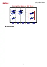
Page 3: ... Memory 256 MB 4 in 1 Print Copy Fax Scan PE MF3c M100 20 ppm color and b w PCL PS Memory 256 MB 4 in 1 Print Copy Fax Scan No hard disk and no optional memory for either model Difference from PE MF2 Both models were 20 ppm in the PE MF2 series and optional memory was available for the PE MF2c Print speeds are for A4 ...

Page 4: ...DDST GDI Memory 64 MB PE P2c M096 20 ppm color and b w PCL PS Memory 256 MB No hard disk and no optional memory for either model Difference from PE P1e Both models were 20 ppm in the PE P1e series and optional memory was available for both models Print speeds are for A4 For LT the speeds are 16 5 and 21 cpm ...

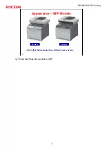
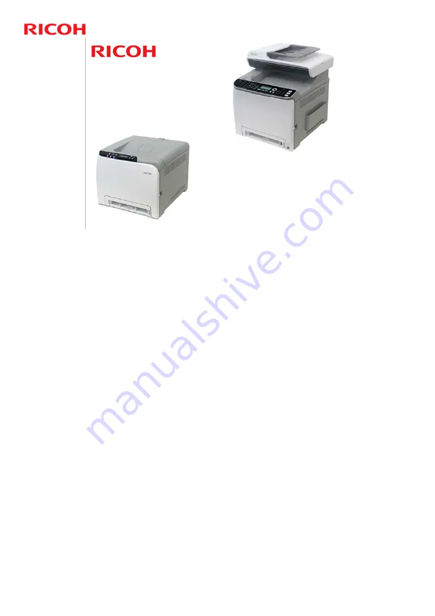
Page 5: ...5 PE MF3 PE P2 Training Slide 5 Appearance MFP Models Note that the two models have different color schemes PE MF3a PE MF3c These machines have a built in ADF ...

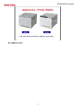
Page 6: ...6 PE MF3 PE P2 Training Slide 6 Appearance Printer Models Note that the two models have different color schemes PE P2a PE P2c No additional notes ...

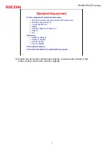
Page 7: ... 250 sheet paper feed unit 1 sheet bypass feed Duplex Ethernet 10Base T 100base TX USB 2 0 Fax Memory PE MF3a 256 MB PE MF3c 256 MB PE P3a 64 MB PE P3c 256 MB No optional memory No hard disk built in or optional for any model Duplex can be used for printing and copying In some earlier models in this series duplex could not be used for copying ...

Page 8: ...Training Slide 8 Optional Equipment TK1010 Paper Feed Unit G849 Available for all models Also used in the PE MF1 MF2 P1 P1E series No optional memory Some of the previous models in this series also had optional memory ...

Page 9: ...FY2011 FY2011 FY2007 FY2007 PE MF1a PE MF1c PE MF1b 3 in 1 GDI Nov 07 FY2010 FY2010 20ppm 20ppm 16ppm PE MF2c Jan 09 20ppm PE MF2b 20ppm PE MF3c Jun 11 20ppm PE MF3a 16ppm 4 in 1 GDI 4 in 1 PCL 4 in 1 PCL 4 in 1 GDI 4 in 1 GDI 4 in 1 PCL Per Mid HY SY Toner Per SY Toner No additional notes ...

Page 10: ...FY2007 PE P1a PE P1c PE P1b GDI Jul 07 FY2010 FY2010 20ppm dn 20ppm n 16ppm n PE P1Ec Feb 09 20ppm dn PE P1Eb 20ppm n PE P2c Jun 11 20ppm dn PE P2a 16ppm dn MD P1c Dec 08 25ppm dn MD P1b 25ppm n PCL PCL PCL PCL GDI PCL MD P2c 25ppm dn Per Mid HY SY Toner Per SY Toner Nov 10 PCL GW CTL PCL GDI Price No additional notes ...

Page 11: ...ec PE MF1a 51 sec The hot roller has a thin wall which makes the warm up time faster and allows lower energy consumption Typical Energy Consumption TEC PE MF3a approx 2 8kWh PE MF1a 4 5kWh PE MF3c approx 3 3kWh PE MF2c 5 9kWh Durability Estimated unit life This is higher for MF3c 180k prints than previous models in this series 90k prints No additional notes ...

Page 12: ...even while seated Economy Color Provides a slightly lighter output with lower printout cost Reduced Toner Usage Motor operation stops during sleep mode recovery Fax Internet fax has been added PE MF3c only Speed Dial 200 locations previous model was only 50 JBIG compression has been added This allows a transmission time of 2 seconds per page previous maximum speed with MMR compression was 3 second...

Page 13: ...c 30 sec PE P1E 48 sec PE P2a 30 sec PE P1a 51 sec The hot roller has a thin wall which makes the warm up time faster and allows lower energy consumption Typical Energy Consumption TEC PE P2c 3 1kWh PE P1Ec 4 6kWh PE P2a 2 3kWh PE P1a 3 2kWh Durability Estimated unit life This is higher for P2c 180k prints than previous models in this series 90k prints No additional notes ...

Page 14: ...ed Economy Color Provides a slightly lighter output with lower printout cost Reduced Toner Usage Motor operation stops during sleep mode recovery Network IPv6 supported not supported in previous models PictBridge Supported at the rear USB socket SOM Smart Organizing Monitor This is not used The technician does not need to use a computer to access service mode Operation is the same as the MF models...

Page 15: ...ax Received indicator Easy to see lamps The operation panel angle is raised so that users can see the lamps even while seated ID Card Copy Button Fax Received Indicator Easy to see Lamps USB Port ID Card Copy Use for printing 2 sided originals such as an ID card on one sheet One side of the original is printed on the upper half of the paper and the other side is printed on the lower half ...

Page 16: ...F3 PE P2 Training Slide 16 Operation Panel Printer Model Two line LCD same as PE P1e Easy to see lamps The operation panel angle is raised so that users can see the lamps even while seated No additional notes ...

Page 17: ...17 PE MF3 PE P2 Training Slide 17 LED Lamps Comparison with Older Models PE P2 PE P1 PE MF3 PE MF1 No additional notes ...

Page 18: ...rtridge The OPC charge roller and development unit are all in an AIO cartridge AIO All in one The cartridge can be removed with one hand The cartridges are the same as used in previous models See the next slide for details No additional notes ...

Page 19: ... 5 k prints per cartridge Same cartridges as PE MF2 Long High Yield Pe MF3c and Pe P2c only 6 5 k prints per cartridge BK 6 0 k prints per cartridge CMY Same cartridges as PE MF2 AIO yield measurements are based on ISO 19798 except for PE MF3a P2a which is based on 5 24P J Note that different cartridge types are used for the short yield AIO PE MF3a P2a uses the PE P1 PE MF1 type AIO PE MF3c P2c us...

Page 20: ...els All consumables can be replaced by customers The waste toner tank is the same as the one that is used for previous models in this series Waste toner tank yield measurement based on 5 3P J 50 color ratio Color ratio 50 means that half the jobs are black and white and half are color Compatible with Pe P1 Pe MF1 Pe MF2 and Md P1 ...

Page 21: ...Average 1 1K prints Maximum 3K prints P2c Average 0 8K prints Maximum 3K prints Estimated Unit Life MF3a P2a 5 years or 90K prints whichever comes first MF3c P2c 5 years or 180K prints whichever comes first Estimated unit life MF3c and P2c are more durable than previous models in this series increased from 90k to 180k ...

Page 22: ...22 Service Modes Printer models and MFP models are all accessed at the machine s operation panel through menus There is no SOM Smart Organizing Monitor Technicians do not need a PC in order to use the service mode No additional notes ...

Page 23: ...raining Slide 23 Service Training M099 M100 M095 M096 Improved Features and Specifications This section provides an overview of the main specifications and explains improvements over the previous models in the PE series ...

Page 24: ...bypass trays 60 160g m2 16lb 40lb Bond Optional paper tray unit 60 105g m2 16lb 28lb Bond Duplex 60 90g m2 16lb 24lb Bond These specs are the same as the previous model except for the warm up time The reason for the faster warm up time will be explained later Why is 1st copy time so much slower than the 1st print time Scanner initialization and movement to the start position takes more time Duplex...

Page 25: ... approx 2 8kWh PE MF1a 4 5kWh PE MF3c approx 3 3kWh PE MF2c 5 9kWh Recovery from Energy Saver Mode Normal Energy Saver Mode 2 30 seconds or less Quick Energy Saver Mode 1 10 seconds or less PDLs PE MF3a DDST GDI PE MF3c PCL5c 6 PostScript 3 emulation Network Protocol TCP IP IPP Bonjour No additional notes ...

Page 26: ...r Input Capacity 250 sheets standard tray 1 sheet bypass tray 500 sheets optional paper tray unit Paper Output Capacity 150 sheets Paper Weight Standard and bypass trays 60 160g m2 16lb 40lb Bond Optional paper tray unit 60 105g m2 16lb 28lb Bond These specs are the same as the previous model except for the warm up time The reason for the faster warm up time will be explained later ...

Page 27: ... 3 1kWh PE P1Ec 4 6kWh PE P2a 2 3kWh PE P1a 3 2kWh Recovery from Energy Saver Mode Normal Energy Saver Mode 2 30 seconds or less Quick Energy Saver Mode 1 10 seconds or less PDLs PE P2a DDST GDI PE P2c PCL5c 6 PostScript 3 emulation Network Protocol PE P2a TCP IP PE P2c TCP IP IPP Bonjour No additional notes ...

Page 28: ...uce energy consumption and to improve the ease of maintenance The hot roller is a thin roller type This means that less power is needed to operate the fusing unit and the unit can warm up quickly Warm up Less than 30sec Typical Energy Consumption TEC PE MF3a 2 8kWh PE MF3c 3 3kWh PE P2a 2 3kWh PE P2c 3 1kWh ...

Page 29: ...MF3 PE P2 Training Slide 29 Economy Color Balances cost and output quality Costs less than full color printing and looks better than monochrome printing Full Color Economy Color Monochrome No additional notes ...

Page 30: ...difference driver settings will be used Any Custom Size type If there is a difference driver settings will be used except when a standard paper size is used in which case a jam occurs Size Mismatch Detection must be enabled with user tools or this function will not work To enable Size Mismatch Detection First access the following special user tool by pressing these buttons OK ESC MENU Size Mismatc...

Page 31: ...erated while recovering from sleep mode in order to maintain machine and print out quality However this operation consumes toner Tests have shown that quality can be maintained without motor operation So for this model the motors do not operate when the machine recovers from sleep mode No additional notes ...

Page 32: ...g Slide 32 FAQs Knowledge Base 1 Customers can access the FAQs and knowledge base for this model through Web Image Monitor http machine s_IP_address Click FAQ Knowledge Base at the top right of the screen No additional notes ...

Page 33: ...33 PE MF3 PE P2 Training Slide 33 FAQs Knowledge Base 2 After you click FAQ Knowledge Base the above screen appears Click Apply The knowledge base is not available in all languages No additional notes ...

Page 34: ...odel Sending using fax or scanner Scanning to USB memory new for this model PictBridge new for this model Printing Color printing new for this model Sending using PC Fax new for this model New for this model security has been added to this feature for the first time in this series Printer models only have PictBridge Printing and Color Printing on this page ...

Page 35: ...35 PE MF3 PE P2 Training Slide 35 Adjustable Louvers for the Fans The customer can now adjust the direction of air that is blown out of the machine No additional notes ...

Page 36: ...is defective No separate color test chart is needed At the bottom there are four rows of numbers These are the contents of the ID chip in the AIO in hex code If a customer asks explain that this is machine status code data for troubleshooting and other purposes To print this page MF models Menu button Printing Lists Reports Printer models Menu button List Test Print ...

Page 37: ...AIOs K C M Y E Consumed short yield AIOs K C M Y F High yield AIO replacement counter K C M Y G Short yield AIO replacement counter K C M Y AIO Type S Short Yield AIO H High Yield AIO AIO type To print this page MF models Menu button Printing Lists Reports Printer models Menu button List Test Print Printer models also have a Test Page in the List Test Print menu ...

Page 38: ...achine life 5 years or 90k prints At 90k the ITB unit fusing unit and transfer roller unit should be changed But with normal use the machine will not make 90k so these parts are normally not replaced However in cases of heavy use 90k may be reached so these parts are called yield parts After replacing reset the counters with these new maintenance modes They are in the Engine Maintenance menu No ad...

Page 39: ... the engine does not stop 1 At 90k no notice appears and the engine does not stop 2 default At near end Replace Soon appears but the engine does not stop At 90k Replace Now appears but the engine does not stop 3 At near end Replace Soon appears but the engine does not stop At 90k Replace Now appears and the engine stops No additional notes ...

Page 40: ...t time after the main power switch is turned on the machine requires some time before it is ready to accept a job This is because the machine is doing process control for the colors In the new models this feature can be turned on off with a user tool System Settings B W Printing Priority In previous models of this series the availability of the function depends on which firmware version is install...

Page 41: ...S model this function is enabled at the machine s operation panel or with Web Image Monitor Improvement of Black Print Quality of MAC GDI PE MF3 P2 has added a printing method to print black and gray data using black toner only This is an improvement request from the customer because the current black is bluish black When the color value of C M and Y are the same K is used for printing black and g...

Page 42: ...42 PE MF3 PE P2 Training Slide 42 Service Training M099 M100 M095 M096 Installation No additional notes ...

Page 43: ...43 PE MF3 PE P2 Training Slide 43 Hardware Installation Procedure The customer installs the machine and options No additional notes ...

Page 44: ...n the fusing pressure is reduced This prevents the hot roller from deforming if the machine is turned off for a long period For normal operation it should be at the up position If the machine power is kept on the fusing unit will idle every 24 hours to prevent damage to the hot roller But if the machine is turned off with pressure still applied the hot roller could deform ...

Page 45: ...45 PE MF3 PE P2 Training Slide 45 Service Training M099 M100 M095 M096 Service Mode No additional notes ...

Page 46: ...nu or Fax Service Menu MF models only at the machine s operation panel Many of the important adjustments are in the Engine Maintenance menu within the Maintenance Mode Menu There is no SOM Smart Organizing Monitor utility Technicians do not need a PC in order to use the service mode Service Manual Service Tables Service Program Overview ...

Page 47: ...item press the Up or Down key Going into the Next Level Returning to the Previous Level To go into the next level of an item select an item then press the OK key To return to the previous level of an item press the Return key Exiting the Engine Maintenance Mode Menu To exit the maintenance mode menu press the Clear Stop or Return key until the Ready display appears In previous models of this serie...

Page 48: ... press the Up or Down key Going into the Next Level Returning to the Previous Level To go into the next level of an item select an item then press the OK key To return to the previous level of an item press the Return key Exiting the Maintenance Mode Menu To exit the maintenance mode menu press the Clear Stop or Return key until the Ready display appears No additional notes ...

Page 49: ...49 PE MF3 PE P2 Training Slide 49 Service Training M099 M100 M095 M096 Updating the Firmware No additional notes ...

Page 50: ...e same In previous models of this series these procedures were different Connect the machine to a PC with USB or an Ethernet crossover cable and follow the procedures in the manual There are two procedures One for engine firmware and one for controller firmware Service Manual Service Tables Firmware Updating ...

Page 51: ...e main power of the machine during firmware updating If you switch the power off the EGB board and or controller board may be damaged If power failed during the download try again If you still cannot download the firmware it may be necessary to change the EGB and or the controller board No additional notes ...

Page 52: ...lete If this message does not appear the download failed Try again You can also switch from an Ethernet connection to a USB connection or the other way around and see if that works If you still cannot download the firmware it may be necessary to change the EGB and or the controller board No additional notes ...

Page 53: ...53 PE MF3 PE P2 Training Slide 53 Service Training M099 M100 M095 M096 Maintenance No additional notes ...

Page 54: ... the Print Cartridges Replacing the Waste Toner Bottle To see the current status of the consumables MF models Menu System Settings Supplies Status Printer models Print the configuration page Menu List Test Print Config Page There are no PM procedures for the technician to do Service Manual Preventive Maintenance ...

Page 55: ... The following items are added to the Engine Maintenance menu Reset Transfer Unit Resets the transfer unit life counter Reset Fuser Unit Resets the fusing unit life counter Reset 2nd Transfer Unit Resets the transfer roller life counter No additional notes ...

Page 56: ...he configuration page Instruct the customer to do the following when the substitute machine gets to the customer site 1 Remove the four print cartridges AIO from the problem machine 2 Install the four print cartridges AIO into the substitute machine 3 Restore the customer settings which are printed on the configuration page by using a web browser 4 Send back the problem machine to the repair cente...

Page 57: ...F3 PE P2 Training Slide 57 Before you Start to Work on the Machine Read all the notes and cautions in the following section of the service manual Replacement and Adjustment Before you Start No additional notes ...

Page 58: ...58 PE MF3 PE P2 Training Slide 58 Service Training M099 M100 M095 M096 Machine Overview No additional notes ...

Page 59: ... the printer 4 Power Switch 5 Bypass Tray 1 sheet 6 Tray 1 Up to 250 sheets of plain paper 7 Top Cover Open Lever 8 Standard tray extension Use this to support sheets that come out curled after they are printed Flip open the extension by pushing down on the end that is toward the rear of the machine 9 Stop Fences Use these to stop legal size or A4 size prints falling behind the machine For legal s...

Page 60: ... you load paper larger than A4 in the paper tray 5 Ethernet Port Use a network interface cable to connect the printer to the network 6 USB Host Interface Use a USB cable to connect a digital camera to the printer You can print images directly from a digital camera without having to connect to a computer The camera must support PictBridge 7 USB Port Use a USB cable to connect the printer to the hos...

Page 61: ...o replace the print cartridges Up to 150 sheets of plain paper can be stacked here Also open here to replace the print cartridges 6 Front Cover Open this cover to replace the waste toner bottle or remove jammed paper 7 Tray 1 Up to 250 sheets 8 Tray 2 option Up to 500 sheets 9 Bypass Tray One sheet only 10 Operation Panel 11 USB Port Insert a USB flash disk for using the Scan to USB function or co...

Page 62: ...4 Rear Cover Remove this cover when loading paper longer than A4 in tray 1 5 Cable Cover Remove this cover when connecting cables to the machine 6 External Telephone Connector 7 USB Port For connecting the machine to a computer using a USB cable Compare with the USB port on the front of the machine 8 Ethernet Port 9 G3 Fax Line Interface Connector G183 G184 only 10 Stop Fences Raise this fence to ...

Page 63: ...e the ADF towards the rear of the machine and hold it in that position if paper output to the output tray is difficult to retrieve Slide the ADF only when the exposure glass cover or ADF is closed Be careful not to trap your fingers when sliding No additional notes ...

Page 64: ...64 PE MF3 PE P2 Training Slide 64 MF Model Stop Fences Raise the fence as shown to prevent prints from falling off For A4 LT Size Prints For LG Size Prints No additional notes ...

Page 65: ...ck K Messages appear on the screen MF models or an indicator lights on the operation panel printer model when print cartridges need to be replaced 2 Waste Toner Bottle Collects excess toner during printing Messages appear on the screen when the waste toner bottle needs to be replaced 3 Transfer Unit Remove this unit when replacing the waste toner bottle ...

Page 66: ...s to enter the user tools menu Use the keys to navigate around the menu 13 B W Start key Press to scan or copy in black and white or start sending a fax 14 Color Start key Press to scan or copy in color 22 Shift key Press if you want to use Quick Dial entries Nos 11 to 20 when specifying a scan or fax destination 25 One Touch Buttons Press to select a scan or fax destination using entries register...

Page 67: ...this key to print the configuration page See the operation manual for details 2 Job Reset key Press this key to cancel a job that is printing out 8 Data In Indicator Flashes when the printer is receiving data from a computer The data indicator is lit if there is data to be printed 9 Alert Indicator Lights up in red whenever printer error occurs Use display to check the error Flashes in yellow when...

Page 68: ...o the paper Waste toner from the drum stays in the AIO No recycling There is also another waste toner tank in the image transfer belt unit 1 Laser Optics Housing Unit 2 Print Cartridge AIO AIO means All in one 3 Development Roller AIO 4 Paper Exit 5 Fusing Unit 6 Fusing Lamp 7 Duplex Path 8 Transfer Roller 9 Registration Roller 10 By pass 11 Paper Feed Roller 12 ITB Image Transfer Belt Unit 13 OPC...

Page 69: ...69 PE MF3 PE P2 Training Slide 69 Original Feed Path 1 Original feed path ...

Page 70: ... PE P2 Training Slide 70 Paper Feed Paths All models have the duplex motor which can reverse the paper into the duplex path 1 Paper path from tray 1 2 Duplex path 3 By pass tray 4 Paper path from tray 2 optional ...

Page 71: ...the three color AIOs C M Y Black AIO Motor Drives the components in the Black AIO Also drives the image transfer belt 1 Color AIO Motor 2 Black AIO Motor 3 Duplex Motor 4 Transport Fusing Motor 5 Registration Clutch 6 Paper Feed Clutch 7 Agitator Motor 8 ITB Image Transfer Belt Contact Motor ...

Page 72: ...rses the paper into the duplex feed path Transport Fusing Motor Drives the paper feed registration rollers and the fusing unit 1 Color AIO Motor 2 Black AIO Motor 3 Duplex Motor 4 Transport Fusing Motor 5 Registration Clutch 6 Paper Feed Clutch 7 Agitator Motor 8 ITB Image Transfer Belt Contact Motor ...

Page 73: ...ives the drum a negative charge The laser beam writes the latent image on the drum Charge Roller Drum Laser Beam This machine uses four AIOs and four laser beams for color printing Each AIO contains a drum charge roller cleaning brush blade development roller and mixing auger ...

Page 74: ... on the drum The image transfer roller pulls the developed toner image onto the image transfer belt Image Transfer Roller Drum Development Roller K The charge that is applied to the image transfer roller pulls the toner from the drum to the transfer belt Four toner images are put on the paper at the same time ...

Page 75: ...ansfer belt onto the paper Paper Transfer Roller Image Transfer Belt Toner transfers from the image transfer belt to the paper when the paper is fed between the image transfer belt and transfer roller After transfer the paper separates from the image transfer belt because of a discharge plate immediately after the transfer roller ...

Page 76: ...he center and one at the right The center TM sensor detects the density of the sensor patterns on the transfer belt The TM sensor output is used for process control and for automatic line position adjustment skew and color registration adjustments for the latent image MUSIC This is the internal process used by the machine to automatically correct for color registration errors to make sure that the...

Page 77: ...akes a 7 gradation pattern on the transfer belt for each toner color The pattern has 9 squares the sequence is as follows 7 yellow squares 7 cyan squares 7 magenta squares and 7 black squares Each of the squares is 10 mm x 17 mm and is a solid color square To make the squares the machine changes the development bias and charge roller voltage The difference between development bias and charge rolle...

Page 78: ...ansfer unit life counter is reset with SP mode 3 No environment change Toner amount control and MUSIC start automatically when the front or top cover is closed if conditions other than described above occur 4 Ready status Toner amount control and MUSIC start automatically when the machine stays in the ready condition and the environment has changed 5 Before a job MUSIC starts automatically before ...

Page 79: ...oller This controls the interface between the OPU and EGB ADF scanner unit and applications The controller connects to the EGB through the PCI Bus Peripheral Component Interconnect Bus LD Drive Board This is the laser diode drive circuit board OPU Operation Panel Unit This controls the display panel the LED and the keypad MUSIC Mirror Unit for Skew and Interval Correction MUSIC is also called Auto...

Page 80: ... P2 Training Slide 80 Accessing the Boards PE MF3 PE P2 Controller Board Fax Board EGB The EGB boards for the P2 and MF3 are identical The controllers for the P2 and MF3 are not identical but use many common parts ...

Page 81: ... the controller cannot be removed The EEPROM on the EGB board can be removed Take the EEPROM from the old EGB board and install it on the new one The mark must point to the right side A Service Manual Replacement and Adjustment Electrical Components EGB Engine Board ...

Page 82: ...ith this SP mode the machine calibrates the motor speed for the new belt the speed is checked with a TM sensor pattern Fuser SC Detect This is normally OFF If you turn this ON the machine will issue SC559 and stop working if three consecutive paper jams occur in the fusing unit Then the technician must visit the machine and reset the SC code and check the fusing unit If a sheet of paper feeds corr...

Page 83: ... PSU The PSU contains a fuse This fuse can be replaced Always use the correct type of fuse or the machine could be damaged See the service manual for the correct type of fuse to install Service Manual Replacement and Adjustment Electrical Components PSU ...

Page 84: ...machine cannot be operated until the SC has been reset by a technician Enter the engine maintenance mode Press O K in Fuser SC Reset with engine maintenance mode and then turn the main power switch off and on Service Manual Appendix 3 Troubleshooting Guide Service Call Conditions There is no SOM Smart Organizing Monitor in this series ...

Page 85: ... 30 mm intervals Charge roller Abnormal image at 38 mm intervals Registration roller Colored spots at 27 mm intervals AIO cartridge Development roller Abnormal image at 61 mm intervals Image transfer belt unit Drive roller Colored spots at 76 mm intervals AIO cartridge OPC drum or the Fusing unit Heat roller Abnormal image at 95 mm intervals Fusing unit Pressure roller Paper Feed Problems at Regul...

Page 86: ...86 PE MF3 PE P2 Training Slide 86 Service Training M099 M100 M095 M096 Document Feed and Scanning PE MF3 only No additional notes ...

Page 87: ...on roller and pick up roller are included in an assembly that is called the ADF Feed Unit After the original set sensor has detected an original and the machine has got a copying or scanning job the ADF motor rotates to pick up and feed a sheet of the original to the feed sensor If the feed sensor does not detect paper after this sequence the machine determines an original jam has occurred The ADF...

Page 88: ...mode the carriage remains below the DF exposure glass and the original feeds above it In platen mode the carriage moves below the main exposure glass to scan the original The scanner contains a CCD Scanner Carriage Unit DF Exposure Glass Main Exposure Glass Carriage Drive Rail No additional notes ...

Page 89: ...g belt Scanner Motor Scanner Carriage Carriage Home Position Sensor The carriage home position sensor E in the scanner carriage unit detects the home position when initializing the scanner or before after scanning The scanner carriage unit moves to read the white plate every scan to adjust white level ADS ...

Page 90: ...E P2 Training Slide 90 Shipping the Machine Do the following user tool to move the scanner to the shipping position before you move the machine Menu key System settings Scanner carriage Execute No additional notes ...

Page 91: ...91 PE MF3 PE P2 Training Slide 91 Replacing the Exposure Lamp Install the cables as shown to avoid damage to the cables when the top cover of the carriage unit is attached No additional notes ...

Page 92: ...92 PE MF3 PE P2 Training Slide 92 Service Training M099 M100 M095 M096 Laser Unit No additional notes ...

Page 93: ...from LD unit The laser beam from the LD unit C M is directed to the Fθ lens at rear side by the polygon mirrors The laser beam from the LD unit K Y is directed to the Fθ lens at front side by the polygon mirrors Laser exposure for magenta and cyan starts from the left side of the drum but for yellow and black it starts from the right side of the drum This is because the units for magenta and cyan ...

Page 94: ... Optical Path K Y M C The laser beams for magenta and yellow are sent to the upper part of the polygon mirror The laser beams for cyan and black are sent to the lower part of the polygon mirror Polygon Mirrors Drums No additional notes ...

Page 95: ...95 PE MF3 PE P2 Training Slide 95 Safety Switches A safety switch disconnects power to the laser diodes when the front cover or the top cover is opened No additional notes ...

Page 96: ...M KY KC KM are measured by the front center and rear TM sensors The controller reads the average of the spaces and adjusts these items Sub scan line position for YCM Main scan line position for KYCM Magnification ratio for KYCM Phase control The transfer belt cleaning unit cleans the transfer belt after the patterns are measured MUSIC is done at the times explained in the process control section o...

Page 97: ...PE MF3 PE P2 Training Slide 97 General Caution Turn off the main power switch and unplug the printer before you start to work on the laser unit Laser beams can cause serious eye injury No additional notes ...

Page 98: ...98 PE MF3 PE P2 Training Slide 98 Laser Optics Housing Unit Always use two hands when carrying the laser optics housing unit Be sure not to drop the laser optics housing unit No additional notes ...

Page 99: ...with the front cover of the machine open On the LCD access LSU Adjustment inside the Engine Maintenance menu Manually input the corresponding LSU data from your supervisor into the space provided on the LCD Close the front cover Execute Color Registration in the Engine Maintenance menu Turn the main switch off on MUSIC will be performed automatically No additional notes ...

Page 100: ...MUSIC was performed successfully 1 Click the Properties tab inside the printer driver 2 Click the Print Quality tab 3 Select the Manual radio button 4 Click Advanced 5 Select Off for the three Color Profile pull down menus shown i e for Text Graphics and Photo modes 6 Click OK twice to print out the test chart No additional notes ...

Page 101: ...f vertical lines appear on the test chart C and k M and k Y and k In each set look for vertical lines that are aligned within the region defined by OK If all sets have at least one set of vertical lines that are aligned MUSIC was successful If MUSIC was successful skip the steps on the next slide 4 Go to slide 5 In each region area at least one set of vertical lines is aligned No additional notes ...

Page 102: ...f it is then do the rest of this procedure 3 Open the front cover and turn on the machine 4 Input the setting values for the laser optics housing unit with LSU Adjustment in the Engine Maintenance menu 5 Close the front cover 6 Execute Color Registration in the Engine Maintenance menu 7 Turn the main switch off on MUSIC will be performed automatically Steps 3 to 7 are a repeat of slide 1 of this p...

Page 103: ...Slide 103 After you Replace the Laser Optics Housing Unit 5 Adjust the registration settings for each tray and for the front and rear side of the paper if necessary Registration in the Engine Maintenance menu No additional notes ...

Page 104: ...104 PE MF3 PE P2 Training Slide 104 Service Training M099 M100 M095 M096 AIO Cartridge No additional notes ...

Page 105: ... Area Development Roller Charge Roller Cleaning Blade Waste Toner Transport Belt Toner Agitator The term AIO means All in One All image creation components are in one easily replaceable unit Each AIO consists of the waste toner tank print cartridge development unit and PCU This gives the user easy replacement procedures and helps to make the engine module more compact The waste toner bottle is sma...

Page 106: ...O motor The three color AIOs are driven by the color AIO motor In each AIO a gear transmits drive from the motor to the other gears and rollers in the AIO No adjustment is needed if you replace the motors Gear The color AIO motor drives the central gear as shown in the diagram below ...

Page 107: ...e high voltage supply board which is at the left side of the machine applies a dc and ac voltage at a constant current to the roller The ac voltage helps to make sure that the charge given to the drum is as constant as possible The machine automatically controls the charge roller voltage when process control is done ...

Page 108: ...eaning blades They always touch the charge roller Waste toner from cleaning goes to the toner collection coil The toner collection coil moves the toner to the waste toner transport belt Charge roller cleaning blades Drum cleaning blade We will see the toner transport belt on the next slide ...

Page 109: ...toner tank at the top of the AIO The collected waste toner is moved to the left side of the AIO by the waste toner collection roller and transfer belt shaft Waste Toner Collection Coil OPC Waste Toner Transport Belt Waste Toner Collection Roller Transport Belt Shaft See the next slide for more about the waste toner tank There is another toner collection mechanism for the image transfer unit and a ...

Page 110: ...A flexible sheet separates the unused toner area from the waste toner area The waste toner area becomes larger when toner is consumed This toner is not recycled Waste Toner Collection Roller Transport Belt Shaft Waste Toner Tank Flexible Sheet No additional notes ...

Page 111: ...per mixing roller moves toner to the center then the lower mixing roller moves toner to the right and left sides Finally the toner supply roller supplies toner to the development roller Toner Agitator Upper Mixing Roller Lower Mixing Roller Development Roller This mixing mechanism prevents toner hardening and uneven image density in the outputs ...

Page 112: ...atic attraction generated by the friction between these two rollers moves toner to the development roller The development blade gives the layer of toner on the development roller an even thickness Toner Supply Roller Development Roller Development Blade This machine uses mono component toner with no carrier so a TD sensor is not necessary ...

Page 113: ...ning Slide 113 Development Roller Discharge The discharge sheet removes charge from the development roller after it has turned past the drum Development Roller Discharge Sheet This system is used instead of a quenching lamp ...

Page 114: ...rinted A4 5 coverage until toner end occurs New for this series This can be changed from 200 to either 100 or 300 sheets These two figures are stored in the memory chip in the AIO Toner near end If you change from the default 200 sheets the near end detection point is moved earlier in the case of 300 sheets or later in the case of 100 sheets How to change the 200 sheet limit to 100 or 300 User too...

Page 115: ...AIO Detection There is a new unit detection mechanism for the AIO It uses the ID chip that is built into each AIO Other units do not have new detection mechanisms For example after the ITB is replaced SP modes must be done No additional notes ...

Page 116: ...116 PE MF3 PE P2 Training Slide 116 Service Training M099 M100 M095 M096 Paper Feed No additional notes ...

Page 117: ...d sensor detects whether paper is installed in the tray and whether the tray is set in the machine This machine does not have a tray set sensor This machine also does not have automatic paper size detection The machine determines the paper size from the on off timing of the registration sensor If the paper type which is selected at the PC does not match the paper size measured by the registration ...

Page 118: ...ls the paper feed roller and registration roller with the paper feed clutch registration clutch and gears The transport fusing motor also controls the fusing unit and paper exit roller Transport Fusing Motor Paper Feed Roller Registration Roller The clutches are shown in blue ...

Page 119: ...s a paper buckle at the registration roller to correct paper skew Then the registration clutch turns on and then the registration roller transports a sheet of paper to the transfer roller unit There is no paper buckle adjustment Transport Fusing Motor Paper Feed Roller Registration Roller No additional notes ...

Page 120: ...3 PE P2 Training Slide 120 Paper End Detection When the paper is finished the feeler falls through a cutout in the bottom of the tray and the sensor detects paper end Paper End Sensor Feeler No additional notes ...

Page 121: ...d in the machine a lock lever is released and springs lift the bottom plate There is no mechanism to lower the tray You must push the bottom plate down A projection at the right side of the tray set location releases the lock lever when the tray is installed in the machine ...

Page 122: ... Feed If the registration sensor detects paper but no job is coming in from the PC the machine detects that a sheet of paper has been placed in the bypass tray The bypass can only hold one sheet at a time Registration Sensor No additional notes ...

Page 123: ...it feeds paper to the duplex mechanism The duplex motor starts to reverse after the paper has gone through the paper exit sensor There is no interleaving Only one sheet can pass through the machine at one time The second side is printed first then the first side Paper Exit Sensor Duplex Motor Duplex Transport Roller No additional notes ...

Page 124: ...PE MF3 PE P2 Training Slide 124 Replacing the Separation Pad When reinstalling the separation pad make sure that the mylar is not placed under the separation pad Mylar Correct Incorrect No additional notes ...

Page 125: ...125 PE MF3 PE P2 Training Slide 125 Service Training M099 M100 M095 M096 Image Transfer No additional notes ...

Page 126: ...t For a full color print all four colors are moved from the PCUs to the transfer belt at the same time The paper transfer roller then moves the four color toner image from the transfer belt to the paper OPC Drum Transfer Belt Paper Transfer Roller Image Transfer Rollers ITB Cleaning Unit No additional notes ...

Page 127: ... PE P2 Training Slide 127 Differences from the Previous Model The ITB unit and transfer roller unit are different parts from the previous model Transfer roller unit Improved cleaning function No additional notes ...

Page 128: ...28 Drive The black AIO motor controls the transfer belt drive roller The belt tension roller adds tension to the transfer belt to help to turn this belt Black AIO Motor Transfer Belt Drive Roller Belt Tension Roller No additional notes ...

Page 129: ...129 PE MF3 PE P2 Training Slide 129 Transfer Voltage The image transfer rollers move the toner from the PCUs to the image transfer belt Image Transfer Rollers No additional notes ...

Page 130: ...ntact cams slide the right and left sliders The sliders lift the belt transfer rollers for the CMY OPCs to the transfer belt Transfer Belt Contact Motor CMY Contact Cam Shaft Sliders CMY Image Transfer Rollers Because of this mechanism the life of the transfer belt is longer it is not necessary for the transfer belt to touch the color PCUs when the machine makes a black and white print However if ...

Page 131: ...tact 2 The ITB contact sensor detects if the transfer roller unit for each OPC CMY touches the transfer belt If it does not touch the transfer belt during color printing the machine stops and shows SC 445 446 or 447 ITB Contact Sensor No additional notes ...

Page 132: ...te toner from the ITB to the waste toner bottle A shutter in the ITB cleaning unit closes when the ITB unit is removed This prevents toner from falling out ITB Cleaning Blade Toner Collection Coil We will see more about the waste toner collection mechanism for the ITB later in this section ...

Page 133: ... transfer roller moves the toner image from the transfer belt to the paper When a sheet of paper goes between the transfer roller and the transfer belt the transfer roller turns with the paper Paper Transfer Roller Spring Transfer Belt In some places you will see the term 2nd Transfer This refers to what the transfer roller does transfer from belt to paper ...

Page 134: ... voltage power supply The discharge plate removes charge that was applied to the paper during paper transfer This helps paper move away from the transfer roller High Voltage Power Supply Discharge Plate The right end of the transfer unit is attached to the terminal from the high voltage power supply when you close the front cover ...

Page 135: ...llection coil moves waste toner from the transfer belt to the entrance of the waste toner bottle The agitator plate makes sure that the waste toner is evenly distributed The agitator motor controls this plate Waste Toner Collection Coil Entrance Agitator Motor No additional notes ...

Page 136: ...When the machine detects that the bottle is full 400 more pages can be printed Then the machine stops Waste Toner Bottle Set Sensor Waste Toner Overflow Sensor If the bottle is not set or if it is full an error message appears on the LCD Waste toner overflow and bottle set sensors These are for the waste toner bottle that collects toner from the transfer belt The waste toner from the drums is coll...

Page 137: ...life of the transfer belt unit is the same as the life of the machine It should only be necessary to replace this unit if it becomes defective What is the Transfer Belt Unit Life Counter The resistance of the belt changes during its life The machine automatically compensates for this by adjusting the transfer voltage For a new belt the life counter must be reset so that the machine applies the cor...

Page 138: ...138 PE MF3 PE P2 Training Slide 138 After you Replace the Paper Transfer Roller or Transfer Roller Unit Execute Reset 2nd Transfer Unit with the Engine Maintenance menu No additional notes ...

Page 139: ...139 PE MF3 PE P2 Training Slide 139 Installing the Registration Roller Make sure that you hook the spring correctly Spring No additional notes ...

Page 140: ...ning unit put it on a sheet of paper A shutter mechanism inside the unit should prevent toner from falling out But a small amount may already be on the exterior Waste toner bottle set sensor waste toner overflow sensor Make sure to connect these up to the correct connectors as explained in the manual No additional notes ...

Page 141: ...141 PE MF3 PE P2 Training Slide 141 Service Training M099 M100 M095 M096 Fusing No additional notes ...

Page 142: ...rrect pressure to the nip between the pressure roller and hot roller When releasing the pressure release levers the pressure roller moves away from the hot roller If a paper jam occurs in the fusing unit releasing these levers make it easy to remove jammed paper Pressure release levers Also known as the envelope levers in this machine because they are used to release pressure between the fusing un...

Page 143: ...ot roller it can be difficult to pull paper off so stripper pawls are added the previous model did not have these A solenoid operates these pawls see the next slide A cleaning roller was added to remove toner dust transferred from the separator pawls to the hot roller Stripper Pawls Hot Roller Cleaning Roller Solenoid No additional notes ...

Page 144: ...om wrapping around the hot roller The fusing stripper pawl solenoid detaches the stripper pawl from the hot roller until contact is necessary This is to prevent stripper pawl lines from appearing in the printed image and to prevent the hot roller surface from being damaged No additional notes ...

Page 145: ...lowing will occur Displayed error message Check Env Lever Position Paper or envelopes are fed with skew so the image appears skewed on the paper Insufficient fusing on one side of the paper Wrinkling Normal Envelope Normally this lever should be up A larger gap is needed for envelopes which are thicker than paper Lower the lever to increase the size of the gap between the hot roller and pressure r...

Page 146: ...ing Slide 146 Fusing Pressure Release Sensor This is a new sensor for this model The sensor detects the status of the levers If the position does not match the paper type a warning appears on the display No additional notes ...

Page 147: ...lide 147 Drive The transport fusing motor controls the hot roller and pressure roller The duplex motor controls the paper exit roller Pressure Roller Hot Roller Paper Exit Sensor Duplex Motor Paper Exit Roller No additional notes ...

Page 148: ...ors one thermostat Fusing temperature control is based on measurements from the thermistor at the center The thermostat cuts power to the fusing lamp The machine turns power off and enters sleep mode if the machine is idle for 10 minutes Thermistors Thermostat No additional notes ...

Page 149: ...and fusing belt rotation No rotation Rotation till 6 s after printing No rotation Rotation till 3 s after ready No rotation Sleep mode Prints 10 minutes 1st print time 14 s 10 s recovery temperature 150 C Warm up time 30 s Switch ON to Ready condition 173 Ready temp 155 Standby temp 80 C Rotation start temp Center thermistor temp C Time seconds Energy Saver 1 No additional notes ...

Page 150: ... 16 C 177 C 1 Letterhead 196 C 160 C 165 C 165 C 160 C 177 C 177 C 177 C 177 C 177 C 177 C 173 C 170 C Temp 1 2 Envelope 1 2 Bond 1 2 Cardstock 1 2 Thick 2 106 to 160 g m2 1 2 Thick 1 91 to 105 g m2 1 Prepunched 1 Preprinted 1 Color paper 1 Plain Middle thick recycled 1 Recycled 1 Middle thick 75 to 90 g m2 1 Plain 66 to 74 g m2 1 Thin 60 to 65g m2 Speed Paper No additional notes ...

Page 151: ...43 and 545 To prevent damage to the machine the machine cannot be operated until the fusing related SC has been reset by a technician To reset the machine Engine Maintenance menu Fuser SC Reset press OK then turn the main power switch off and on No additional notes ...

Page 152: ... enables this function in the user mode Mode 1 No fusing idling transfer roller voltage is increased Mode 2 Fusing unit rotates for 30 seconds before a job transfer roller voltage is increased Mode 3 Fusing unit rotates for 60 seconds before a job transfer roller voltage is increased Lab tests Fusing idling mode 2 should be enough in most cases Menu Machine Settings High Humidity Mode ...

Page 153: ...153 PE MF3 PE P2 Training Slide 153 Stripper Pawl Solenoid This is a new component for this series No additional notes ...

Page 154: ... PE MF3 PE P2 Training Slide 154 Replacement Make sure that the fusing unit is cool before you touch it Make sure to restore the insulators shields etc after you service the fusing unit No additional notes ...

Page 155: ...nged from the previous model To remove the fusing unit it is not necessary to remove both left and right covers Remove the left cover only This is because the thermistor harness is only on the left side in the new machine The red circle shows the thermistor harness ...

Page 156: ...156 PE MF3 PE P2 Training Slide 156 After Replacing the Fusing Unit Execute Reset Fuser Unit with the Engine Maintenance menu if the fusing unit is replaced No additional notes ...

Page 157: ...mp A which shows the voltage and power rating must be placed at the left side of the fusing unit The thermistors and thermostat cannot be replaced in the field The position of these components is adjusted precisely in the factory with special tools This is different from PE MF2 ...

Page 158: ...158 PE MF3 PE P2 Training Slide 158 Reassembling the Fusing Unit Route the harness A as shown above when reinstalling the back cover B No additional notes ...

Page 159: ...ly the user will remove fusing unit jams But if the service program Fuser SC Detect is changed to on the machine stops if a jam occurs in the fusing unit for three consecutive paper feeds Then SC559 appears The technician must remove the jam No additional notes ...

Page 160: ...160 PE MF3 PE P2 Training Slide 160 Service Training M099 M100 M095 M096 Optional Paper Tray Unit G849 No additional notes ...

Page 161: ...aining Slide 161 Overview Capacity 500 sheets Feed roller and friction pad 1 Side Fence 2 Paper End Sensor 3 Paper Feed Roller 4 Relay Sensor 5 Relay Roller 6 Friction Pad 7 Paper Height Lever 8 Bottom Plate 9 Rear Fence ...

Page 162: ...PE P2 Training Slide 162 Feed The transport fusing motor in the main machine drives the gear The clutches transfer drive to the rollers at the correct times Relay Clutch Gear Paper Feed Clutch No additional notes ...

Page 163: ...ushes the bottom plate up So you must press the bottom plate down before you put the tray in the machine After the bottom plate is pressed down the tabs hold the lock levers Lock Levers Tabs The next slide shows what happens after you put the tray in the machine ...

Page 164: ...de 164 Paper Lift 2 When you put the tray in the machine the guides in the main body of the paper tray unit push the lock levers and the lock levers release the tabs Then the spring lifts the bottom plate Guides No additional notes ...

Page 165: ...ide 165 Paper End Detection When there is no paper in the tray a feeler drops through a cutout in the bottom plate and the actuator attached to the feeler enters the paper end sensor Sensor Feeler Feeler Cutout No additional notes ...

Page 166: ...lide 166 Reinstalling the Friction Pad When re installing the friction pad make sure that the Mylar does not go under the friction pad Friction Pad Mylar G849 Service Manual Replacement and Adjustment Paper Feed Unit Friction Pad ...

Page 167: ...167 Environmental Conservation Technology for Environmental Conservation Energy Saving Paper Saving This section explains the technology used in this machine for environmental conservation and the default settings of related functions ...

Page 168: ...ing down on paper consumption Improves machine productivity when printing out duplex double sided images 5 High speed duplex copying Improves machine productivity when printing out duplex double sided images 6 Ozone reduction design Low ozone emissions 7 PxP polymerized toner Energy saving Conservation of materials resources reduced toner consumption 8 Noise reduction design Low noise 9 Minimizati...

Page 169: ...chine to warm up to the Read condition This is made possible through the utilization of dual fusing lamp heating low fusing point toner a pressure roller with a sponge surface layer and a thin surface layer hot roller 2 Hybrid QSU This technology adds a capacitor to conventional QSU Technology which allows the benefits of reduced energy consumption and reduced warm up time described above to be ex...

Page 170: ... the benefits of reduced energy consumption and reduced warm up time to be extended to color machines 4 Paper saving features 1 The duplex double sided and Combine features reduce paper consumption 2 The Document Server and other electronic document management features reduce paper consumption by offering an electronic method for storing and managing important documents No additional notes ...

Page 171: ... Interleaf and high speed Inverter Transport features 2 Enables quick printing of duplex jobs through the use of Duplex Scanning 6 Ozone reduction design Greatly reduces the machine s ozone emissions to near zero levels by utilizing 1 A charge roller belt instead of a corona wire 2 An image transfer roller belt instead of a corona wire based transfer system No additional notes ...

Page 172: ...f the conventional pulverization method This allows the toner to fuse at a lower temperature which reduces the impact on the environment and contributes to achieving even higher image quality than before PxP toner also has other benefits including a reduction in the amount of toner needed to develop the image as well as an approximate 35 reduction in CO2 emissions during the toner manufacturing pr...

Page 173: ...ocal laws and regulations as well as user requirements in each market in which the products are sold 2 Reduces the noise generated by the polygon mirror motor 9 Minimization of harmful substances 1 Products sold in the EU conform to the RoHS Directive 2 Products sold in China conform to China s version of the RoHS Directive 3 In addition Ricoh imposes strict internal standards for limiting the pre...

Page 174: ...ling Enables effective use of resources by recycling reusing the toner left over on the drum surface after image transfer 12 Recycle friendly design To maximize the recycling ratio of machine and component materials as well as the ease of performing the recycling in the field machine sections and components are designed so that the recyclable parts can be separated out easily In addition component...

Page 175: ... power consumption by turning off the LCD of the operation panel and lowering the fusing temperature The area shaded green in this diagram represents the amount of energy that is saved when the timers are at the default settings If the timers are changed then the energy saved will be different For example if the timers are all set to 60 minutes the green area will disappear and no energy is saved ...

Page 176: ...aver mode Printer We recommend that the default settings should be kept If the customer requests that these settings should be changed please explain that their energy costs could increase and that they should consider the effects on the environment of extra energy use If it is necessary to change the settings please try to make sure that the Auto Off timer is not too long Try with a shorter setti...

Page 177: ... operation panel Mode Operation Switch LED Energy Saver LED Power Indicator LED Energy Saver 1 On Energy Saver 2 Sleep Mode On Energy Saver mode 1 Energy Saver mode 1 is displayed in the operation panel LCD Energy Saver mode 2 Sleep mode Energy Saver mode 2 is displayed in the operation panel LCD No additional notes ...

Page 178: ...nergy saver mode 1 is off The machine lower the fusing temperature and energy saver mode 1 is displayed on the LCD of the operation panel The machine recovers to the ready condition if one of the following occurs MF version The machine receives a print job prints a received FAX The Copy Color Start or B W Start key is pressed Printer version The machine receives a print job Stop Start key on the c...

Page 179: ...ode is used instead of auto off mode The machine enters sleep mode when the energy saver mode 2 timer runs out after the last job When the machine enters sleep mode no power is supplied to the printing engine and almost none to the controller Recovery time Less than 30 seconds No additional notes ...

Page 180: ...ts the operation panel stays light Then after the job is completed the machine returns to energy saver mode 1 and 2 sleep mode in the same routine Energy Saver mode 1 Operation Mode Warm up Energy saver mode 2 Sleep Mode Power Consump Time Plug in Warm up Ready Mode Data is received Energy Saver mode 2 Sleep Mode Operation Mode Energy Saver mode 1 Ready Mode No additional notes ...

Page 181: ... Energy Save Effectiveness 1 There are no SP modes to keep a log of the amount of time that the machine spends in each mode To get an exact measurement at the customers site a watt meter must be used to measure the actual energy consumed No additional notes ...

Page 182: ...onsumption figures for each model are acquired from Publication System of MSDS_ _PEI PRODUCT ENVIRONMENT INFORMATION database Example 10 W Energy saver mode 2 Sleep mode 80 W Energy saver mode 1 90 W Ready mode Stand by 410 W Operating mode Power consumption Mode condition No additional notes ...

Page 183: ... Saving 3 1 Measuring the Paper Consumed 1 1 Duplex Reduce paper volume in half 1 2 1 2 2 Combine Reduce paper volume in half 3 Duplex Combine Using both features together can further reduce paper volume by 3 4 1 2 3 4 1 234 No additional notes ...

Page 184: ...184 PE MF3 PE P2 Training Slide 184 No additional notes ...

Reviews: