
WIRELESS ZONE EXTENSION
REPEATER
«CN-Repeater»
Installation Guide
1 General Information
Wireless zone extension repeater «CN-Repeator» (hereinafter, the
CN-Repeator) is intended for operation as a part of multicomponent
fire control panels (FCP) and/or security control panels (SCP),
providing two-way address exchange of encoded identified signals
(messages) with wireless security and fire detectors and other terminal
devices (hereinafter, the «TD»), and retransmission of the received
information via the radio channel in the frequency range from 433.05
to 434.79 MHz by the protocol «CN-Contact-R».
CN-Repeator retransmits received information by the
«CN-Contact-R» protocol ver. 6 and higher.
Total number of TD conneced to CN-Repeator is not more than 31.
CN-Repeator is powered by an external stabilized DC power supply
with nominal voltage 10...15 V.
CN-Repeator provides the possibility of hooking up to external device
(hereinafter, ED): personal computer (hereinafter, «PC») or any other
device supporting CDC-ACM interface of the virtual communication
port via USB and is intended for internal software update.
2 Specifications
Table 1
Parameter
Value
Power supply, V DC
10 ... 15
Maximum consumed current, mA
50
Operating temperature,
о
С
from minus 30 to
+50
Dimensions, mm, maximum
82 х 57 х 32
Weight, kg, maximum
0.06
IP rating
IP20
Operating frequency range, MHz
433.05 – 434.79
Maximum output power, mW
10
CN-Repeator is designed for continuous operation around the clock.
3 Scope of Delivery
Each BRSS-RK-RTR unit package contains items listed in Table 2.
Table 2
Name
QNT
Wireless zone extension repeater «CN-Repeator»
Antenna
Screw 3-3х30.016
Wall plug NAT 5х25 SORMAT
Wireless zone extension repeater «CN-Repeator». Installation
Guide
1 pc.
1 pc
2 pcs.
2 pcs.
1 copy
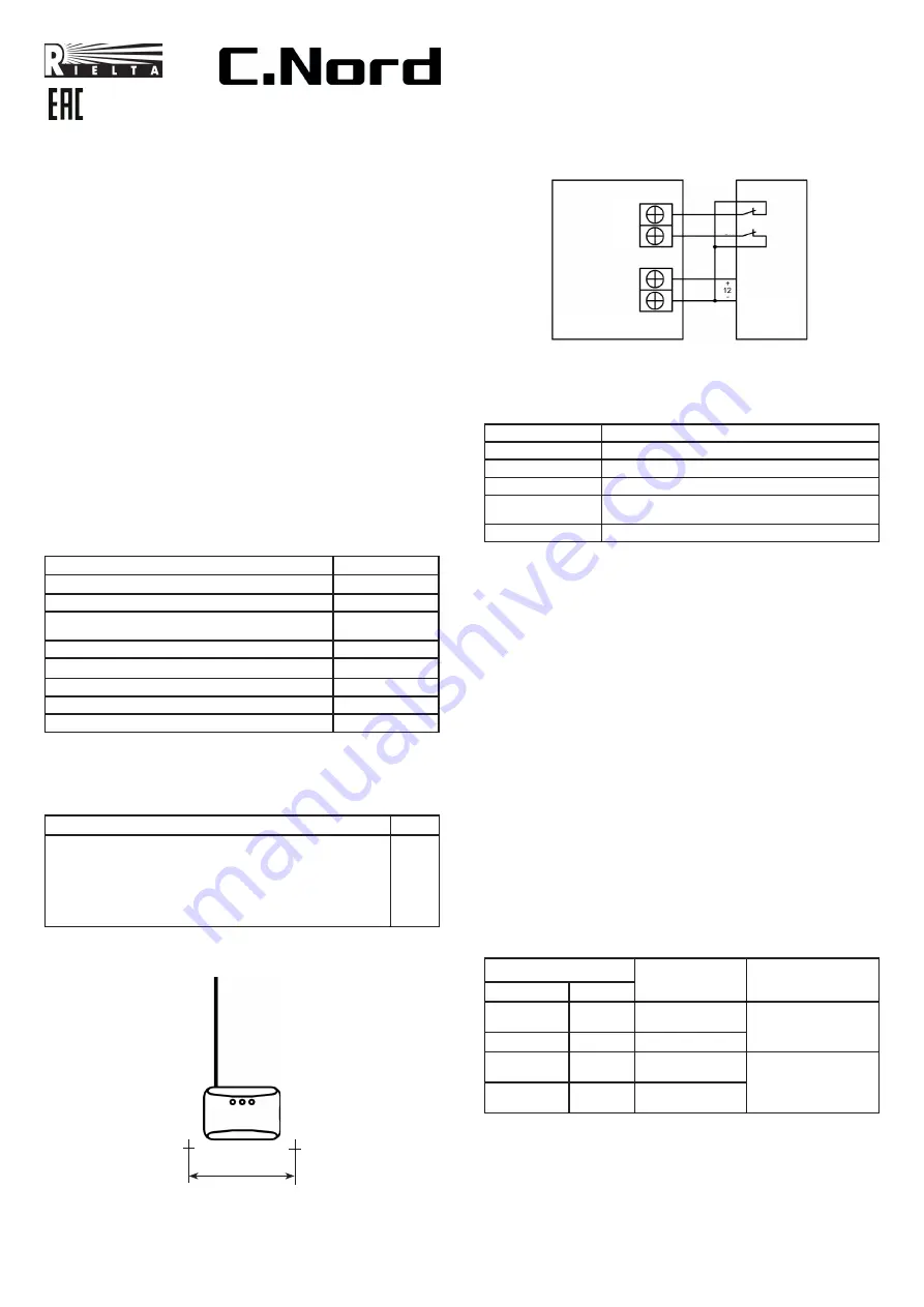
4 Design
CN-Repeator design and markup scheme are shown in Figure 1.
Figure 1
63
On the front panel yellow, red and green LED indicators are located.
The LEDs display the CN-Repeator status (see Table 3). The following
elements are arranged under the CN-Repeator cover: terminals for
external power supply connection, antenna and microswitch for tamper
protection.
5
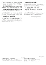
CN-Repeator connection
CN-Repeator connection is fulfilled in accordance with connection
pattern 3.
6 LED Indication
LED indication modes are listed in Table 3.
Table 3
Operation mode
LED Indication
Binding
LED indicator intermittent lighting green
Binding is finished
LED indicator short-term (2 sec) lighting red
Identification
Alternate green and red indicators blinking
Communication
quality appraising
See Table 4
Bootloader mode
Red LED indicator steadily blinking
7 Switching ON and Setting up
7.1 Open cover and install antenna into terminal block.
7.2 Prepare control panel (CP) to logging the new device («Binding»
procedure) in accordance with the CP manual.
During binding procedure only one CP, which is prepared for the
procedure, should be located in the CN-Repeator radio coverage
zone. Supply 12 V on terminals «-12 V+».
7.4 Close «RESET» pin contacts located on the CN-Repeator PCB.
7.5 Assure yourself of periodical greed LED blinking («Binding»
mode). Open pin contacts.
7.6 Fulfill binding procedure in accordance with the CP manual.
7.7 Wait untill red LED indicator short-trerm blink.
Note
– Binding mode is active during 100 sec since the
CN-Repeator energizing. To restart binding it is necessary to repeat
Cls. 7.5 – 7.8.
8 Communication Quality Appraising
8.1 Bring the CN-Repeator prepared for operation to the assumed
place of installation and locate it in such a position, that antenna has
vertical orientation.
8.2 Press tamper contact and hold it during 3 s or more.
8.3 Release tamper contact.
8.4 Appraise CN-Repeator communication quality with the CP by
LED indication modes (see Table 4).
Note
– A delay of up to 4 sec between tampering and LED
indication switching on is possible.
Table 4 – LED Indication during communication quallity appraising
LED Indication
Communication
Quality Appraisal
Recommendations
Color
Mode
Green
Three
blinks
Excellent
Install the
CN-Repeator
at this place
Green
Two blinks
Good
Green
One blink
Communication
established
Choose another place
of installation
Red
A series of
blinks
No communication
9 Recommendations on Installation
9.1 Appraise communication quality at the assumed place of
CN-Repeator installation.
9.2 Install CN-Repeator at the place where communication quality
is apprised as «excellent» or «good» (see Cl. 8)
Figure 3
RP
MP
Power
supply
1 Output 2
-12 V+
«CN-Repeator»


