1 General Information
1.1 Wireless repeater CN-Repeater-AC (hereinafter, the CN-Repeater)
is intended for operation as a part of multicomponent control panels
(hereinafter, the CP) and for retransmission of information from wireless
security and fire detectors or other terminal devices (hereinafter, the TD).
Retransmission is fulfilled within 433.05 … 434.79 MHz frequency
range via a wireless two-way communication by the «CN-Contact-R»
protocol.
1.2 Two frequencies: main and reserve are used for radio exchange
with the CP. Changeover to the reserve frequency is fulfilled
automatically in case of interference at the main one.
1.3 The transmitter radiated power does not exceed 10 mW.
1.4 The CN-Repeater is powered by AC mains with 230 V nominal
voltage.
1.5 Reserve power is supplied by the built-in storage battery LIR14500
type with nominal voltage 3.7 V and capacity 600 mA*h. Storage battery
is withdrawable.
1.6 On-stream time in normal conditions with fully-charged storage
battery in working order is not less than 24 hours.
1.7 The CN-Repeater generates and transmits by radio communication
to CP the following messages:
- «Norm»;
- «Tamper» – in the event of case tampering;
- «
Main power supply failure
» – under main voltage supply absence;
- «Reserve power supply failure» – under storage battery discharge
with voltage drop lower than 3.5
-0.3
V.
1.8 The CN-Repeater fulfills storage battery additional charging (with
exception of bootloader mode). Storage battery is not charged at battery
voltage lower than 2.5 V and under the temperature lower than 0 °С.
1.9 Regular radio communication session period is assigned by the
command from the CP at 10, 15, 30 sec, 1, 2, 5, 10 min intervals.
1.10 The CN-Repeater operation modes are displayed by two LED
indicators (see Table 3).
1.11 The CN-Repeater is designed to operate continuously, around
the clock inside closed premises of residential buildings and production
buildings and facilities.
1.12 The CN-Repeater is resistant to the impact of electromagnetic
fields, electrostatic discharges and nanosecond pulse interferences.
2 Specifications
Table 1
Parameter
Value
Supported wireless devices, items
Up to 31
Power supply, V AC
230 V (184 – 253 V),
50 Hz (±3 Hz)
Maximum consumed power from mains, VA
1.5
Operating temperature, °C
minus 20 … +45
Storage battery charging temperature range, °C
0 … +45
Permissible humidity at a temperature 40 °C, %
93
IP rating
IP30
Dimensions, mm, not more than
66 х 66 х 35
Weight, kg, not more than
0.2
Average service life, years
10
3 Scope of Delivery
Each CN-Repeater unit package contains the items listed in Table 2.
Table 2
Name
QNT
Wireless repeater CN-Repeater-AC
Antenna
Screw 3-3х30.016
Wall plug «SORMAT» NAT 5х25
Storage battery LIR14500 type
(capacity not less than 600 mAh)
Wireless repeater CN-Repeater-AC. Installation Guide
1 pc.
1 pc.
2 pcs.
2 pcs.
1 pc.
1 copy
4 Protective Measures
4.1 Exploitation of the CN-Repeater should be fulfilled in accordance
with rules of technical exploitation and protective measures for
electricity-generating equipment.
4.2 Provider of dangerous voltage in the power source is mains
socket.
4.3 Assembling and disassembling should be fulfilled only when
CN-Repeater is de-energized. Storage battery should be removed.
4.4 CN-Repeater binding and quality apprising procedures should
be carried out during storage battery power supply only.
5 Design
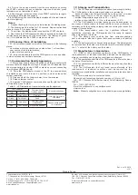
The CN-Repeater layout with removed cover is shown in Figure 1. The
base (1) comprises the following elements:
- hole (6) for cover fixation;
- two holes (2) for CN-Repeater fastening to mounting surface;
- recess (13) for power cord wiring.
Printed circuit board (PCB) (7) comprises the following elements:
- pin contacts START (3);
- contacts BOOT for USB-UART hook up (4) for firmware upgrade;
- tamper (5);
- antenna hook-up socket (8);
- green LED indicator (9);
- red LED indicator (10);
- storage battery in the holder (11);
- mains socket 230 V AC (12).
Installation Guide
WIRELESS REPEATER
CN-Repeater-AC
6 External Connections
Lead-in power supply cords should be protected by double insulation
and should have diameter 0.75 … 1.5 mm
2
.
7 LED Indication
Table 3
Operation mode
LED Indication
Energizing
Green LED indicator continuous lighting
Binding
Green LED indicator intermittent lighting
Binding is finished
Red LED indicator short-term (2 sec) lighting
Identification
Alternate green and red indicators blinking
Bootloader mode
Red LED indicator blinking
Quality appraising
See Table 4
8 Switching ON and setting Up
As a general matter, operating procedure consists of the following
steps:
- CN-Repeater binding with CP (CN-Repeater logging in the CP);
- choosing place of installation and communication quality appraising;
- CN-Repeater mounting on the place of installation.
9 Binding
9.1 Main power supply should be switched off to avid contact with
mains socket with dangerous voltage. Binding procedure should be
fulfilled with the CN-Repeater supplied by storage battery. The previous
settings are deleted after binding has been finalized.
9.2 Prepare CP to logging the new device (
«Binding» procedure)
in accordance with the CP Manual. During CN-Repeater binding
procedure only one CP, prepared for the procedure, should be located
in the radio coverage zone.
9.3 Untwist the screw on the CN-Repeater front side and remove
the cover. Remove an insulator between storage battery «
+
» contact
and holder.
Figure 1 – CN-Repeater-AC with removed cover
START
BOOT
RTR isp2 v10.1
АС
L
N
1
2
3 4
5
6
8
7
9
10
11
12
2
13


