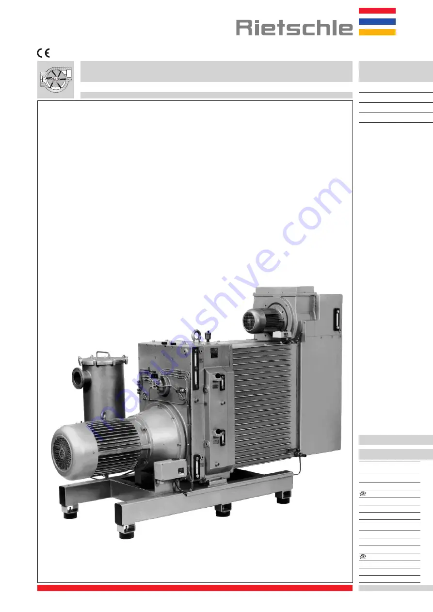
background image

VWZ

702

VWZ 1002

VWZ 1202

VWZ

Vacuum pumps

Instruction and service manual
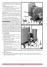
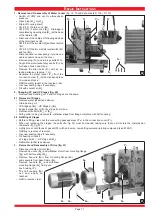
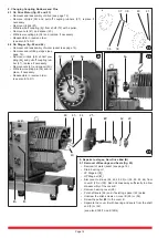
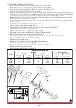
Repair Instructions

BE 134

1.4.99

Werner Rietschle
GmbH + Co. KG

Postfach 1260

D-79642 Schopfheim

0 76 22 / 3 92-0

Fax 0 76 22 / 39 23 00

e-mail: info@rietschle.com

http://www.rietschle.com

Rietschle (UK) Ltd.

Bellingham Way

New Hythe

Kent ME20 6XS

0 16 22 / 71 68 16

Fax 0 16 22 / 71 51 15

e-mail: info@rietschle.co.uk

http://www.rietschle.co.uk

Summary of Contents for VWZ 1002

Page 1: ...s BE 134 1 4 99 Werner Rietschle GmbH Co KG Postfach 1260 D 79642 Schopfheim 07622 392 0 Fax 07622 392300 e mail info rietschle com http www rietschle com Rietschle UK Ltd Bellingham Way New Hythe Kent ME20 6XS 01622 716816 Fax 01622 715115 e mail info rietschle co uk http www rietschle co uk ...

Page 2: ...9 7 Maintenance 9 7 1 Oil Metering Pump 9 7 2 Oil Mist Separator 10 7 2 1 Maintenance of Oil Mist Separator 10 8 Trouble Shooting 10 8 1 Pump Overload 10 8 2 Drop off of Vacuum 10 8 3 High Oil Consumption 10 Repair Instructions VWZ 102 VWZ 402 1 Removal and Reassembly of Water Jacket 11 2 Changing LP and HP Stages 11 2 1 Removal of Stages 11 2 2 Refitting of Stages 11 3 Removal and Reassembly of D...

Page 3: ...e gases or vapours only on request with our company Please contact your local Rietschle office for advice For installation in explosion proof or special areas motors conforming to the relevant standard must be fitted For installations that are higher than 1000 m above sea level there will be a loss in capacity For further advice please contact your supplier All applications where an unplanned shut...

Page 4: ...t separator J3 Drain cock for oil mist separator L Oil pump L1 Oil pump feed line L2 Oil pump leakage line L3 Lubrication LP stage drive end L4 Lubrication LP stage non drive end L5 Lubrication HP stage drive end L6 Lubrication HP stage non drive end L7 Bearing lubrication LP stage L8 Bearing lubrication HP stage L9 L10 Lubrication pump chamber and slot LP stage L11 L12 Lubrication pump chamber an...

Page 5: ...crystallisation vacuum degassing vacuum packing of moist products concentration of liquids juices and extracts Z Oil mist separator Z1 Flushing unit with integrated add oil tank 3 3 Data sheets and spare parts lists see following data sheets D 134 DA 134 USA External cooling VWZ 702 VWZ 1202 14 D 137 DA 137 USA Circulation cooling VWZ 702 VWZ 1202 13 see following spare parts lists E 165 1 Parts f...

Page 6: ...acket might be very hot WARNING Do Not Touch The VWZ is vibration free so a special foundation fastening is not necessary When positioning the pump it is important to ensure that it is mounted horizontally and that there is easy access for routine checking of instruments topping up of oil and water systems and for repair work on the motor pump A clearance of 0 5 m should be allowed to the nearest ...

Page 7: ...gear for compatibility with your available supply voltage frequency permissible current etc Connect the motor to the incoming supply It is advisable to use thermal overload motor starters to protect the motor and wiring All cabling used on starters should be secured with good quality cable clamps We recommend that motor starters should be used that are fitted with a time delayed trip resulting fro...

Page 8: ... cleaned periodically depending on the water quality To do this unscrew the nut U51 and clean the element 6 1 2 Closed Circuit Cooling fig 13 Forstarting upthepump VWZ702 VWZ1202 13 The recommended coolant is a 50 antifreeze mix which is poured into the heat exchanger at point H4 to a level midway up the upper sight glass I4 The filling should not take place under pressure and the antifreeze shoul...

Page 9: ...rt up severe damage may occur if there is debris in the pipework We therefore recommend a vacuum tight inlet filter of 5 micron rating is installed for start up Start the pump momentarily to check the direction of rotation arrow O D 134 D 137 As an option the motor coupling can be fitted with a unidirectional free wheel device to prevent the vacuum pump rotating in the event of incorrect motor rot...

Page 10: ...e and oil mixture from the base of the separator and this can be arranged for manual or automatic operation A level switch V7 is fitted as standard and this will shut down the pump when the exhaust condensate level becomes too high For the drain cock J3 as shown a solenoid valve is available for automatic drain of oil condensate as an optional extra 8 Trouble Shooting 8 1 Pump Overload 1 Check oil...

Page 11: ...ig 20 Removal and Refitting of LP and HP stages are the same 2 1 Removal of Stages Remove water jacket see above Drain bearing oil LP Stage at K1 HP Stage at K2 Support stage S1 or S2 by slings from crane Remove allen bolts S11 or S21 With gentle rocking movements withdraw stage from flange complete with half coupling 2 2 Refitting of Stages Before refitting clean out the connecting passage ways Y...

Page 12: ...age 12 Remove circlips 38 at half cou pling G4 and pull off coupling rub ber 37 replace if necessary Remove nuts 41 and spacer 40 Withdraw coupling pin 36 and re place if necessary Reassemble in reverse order see also E 165 1 5 Repairs to stages Non Drive End B 5 1 Removal of Bearings and Seals fig 25 Removal of water jacket see page 12 Drain bearing oil LP Stage at K1 HP Stage at K2 Disconnect oi...

Page 13: ...shaft seal 12 with sleeve in wearing disc 11 Insert wearing disc 11 together with o ring 13 in bore of end cover with sleeve type I W1 Insert shaft seal 12 with sleeve in sliding ring 15 Slightly oil seal surface of wearing disc 11 and sliding ring 15 Insert sliding ring 15 up to the wearing disc 11 and pull off sleeve type I W1 Slightly oil spring 20 and insert in bore of transporting ring B 17 P...

Page 14: ...are constructed similarly 7 1 Removal of Bearings and Seals see fig 28 and E 165 1 E 165 4 Removal of water jacket and compressor stage see page 12 Disconnect oil lines on end cover A 8 or 54 and bend oil lines away sufficiently to allow dis assembly of the cover Remove threaded pin 45 from the coupling 35 and pull coupling from shaft end using a puller Remove screws from bearing cover 22 and remo...

Page 15: ... to the wearing disc 11 Pull off sleeve type I W1 Tighten end cover 25 or 55 Slightly oil spring 20 and insert in transport ring A 16 Place the transport ring A 16 over the shaft end insert sleeves 19 in the bore of the sliding ring 15 Transport ring A 16 should be set so that the end of the threaded pin 18 will lock the transport ring A 16 in the location on the inner ring 4 placed on the shaft e...

Page 16: ...he puller W7 loosen the gearbox housing 70 from the locating pins 108 while turning the screws simultaneous and remove it Re assembly in reverse order Note the following Bearing cover 80 and shaft seal 82 will be carefully pushed without sleeve along the shaft Bearing cover 81 and shaft seal 82 will be mounted with assembly sleeve type III W3 Re assembly of drive see page 12 Refill with oil see da...

Page 17: ...sure Relief Valve fig 34 Remove allen screws in the valve 400 Carefully remove the valve 400 straight from the intermediate housing Check all parts and the valve seat in the connection housing 89 If necessary regrind the valve seat Before re assembly check that the valve 404 slides easily in the valve sleeve 401 Assembly is in the reverse order 10 Instructions for storing fresh oil lubricated rota...

Reviews: