background image


PT2E-1700 


Smart Transmitter/Gas Detector Head 

SD-1DGH 

Operating Manual 

(PT2-170) 


Request for the Customers 

  Read and understand this operating manual before using the detector. 

  Use the detector in accordance with the operating manual. 

  Regardless of warranty period, we shall not make any indemnification for accidents and 

damage caused by using this product. 
The compensation shall be made only under the warranty policy of products or parts 
replacement. 

  Because this is a safety unit, a regular maintenance for every six months and daily 

maintenance must be performed. 

  If any abnormality is found in the detector, notify it to RIKEN KEIKI immediately. 


Summary of Contents for SD-1DGH

Page 1: ...ng manual Regardless of warranty period we shall not make any indemnification for accidents and damage caused by using this product The compensation shall be made only under the warranty policy of pro...

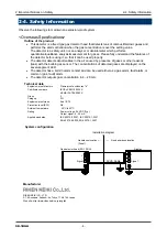
Page 2: ...e by the fail alarm Technical Data Protection Method Flameproof enclosure d Certificate numbers IECEx KEM 10 0036X KEMA 10ATEX0083 X Group II Category 2G Type of Protection and Marking code Ex d IIC T...

Page 3: ...1 Preparation for start up 22 5 2 Basic operating procedures 22 5 3 How to start the detector 23 5 4 Modes 25 5 5 User mode 26 5 6 How to exit 28 6 Operations and Functions 29 6 1 Gas alarm activation...

Page 4: ...on when the gas concentration is over the setting value The detector is a safety unit not an analyzer or densitometer which performs quantitative qualitative analysis measurement for gases Please full...

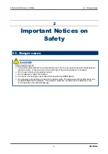
Page 5: ...ndow plate to be changed Do not open the lid when applying current Do not attempt to repair the detector For the lid use hexagon socket head bolts specified by RIKEN KEIKI Do not apply a strong force...

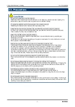
Page 6: ...heric pressure Be sure that excessive pressure is not applied to the sampling inlet and outlet GAS IN GAS OUT of the detector Detected gases must be exhausted from the detected gas exhausting outlet G...

Page 7: ...monitor the temperature humidity of the sampling point to prevent condensation inside the tube In particular when detecting a gas which is dissolved into water and corrodes contacted materials such a...

Page 8: ...the built in gas sensor The concentrations of detected gases are displayed on the seven segment LED The detector has a built in alarm contact and can be used either as a gas alarm fault alarm or commo...

Page 9: ...accessories are used key operations cannot be accepted properly 3 Product Components 3 1 Main unit and standard accessories Main Unit including a cable gland Standard Accessories Operating manual Ded...

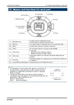
Page 10: ...arm setpoint value is reached 7 Fault lamp Fault lamp It lights up in yellow when an abnormality is detected in the detector 8 Concentration value display Displays the gas concentration and so on NOTE...

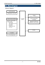
Page 11: ...NPUT 24 VDC Power supply part Gas alarm contact ALARM Contact activation De energized De energized at a normal environment ON ALARM Closed contact at an alarm time Alarm contact controller Display POW...

Page 12: ...ks The detector consists of sensitive electronic parts The detector must be installed in a stable place without vibrations or shocks and it cannot drop Do not install the detector in a place exposed t...

Page 13: ...installing the detector in machinery the machinery must be grounded properly Do not install the detector in a place where other gases exist around it The detector must not be installed in a place whe...

Page 14: ...mation on how to use a lightning arrester please contact the manufacturer Grounding In addition to lightning there are more sources of surge noise To protect units from these noise sources the units m...

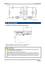
Page 15: ...of the machinery must be removed to perform maintenance or where the detector cannot be removed because tubes or racks prevent access to it Do not install the detector in a place where maintenance inv...

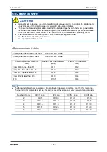
Page 16: ...ed handling lever to wire Use appropriate cables to wire 4 5 How to wire Recommended Cable 3 wire when the contact is not used CVVS1 25 sq 3 core 5 wire when the contact is used CVVS1 25 sq 5 core Cab...

Page 17: ...re wire length may cause defective insulation or a short circuit Be careful not to break up the wire If the wire is broken up when inserted to the terminal this may cause defective insulation or heati...

Page 18: ...ctric conduction or heating Compatible bar terminal For a bar terminal the following items are available Bar terminal ferrule Model 216 Series manufactured by WAGO Crimping tool Model VarioCrimp 4 206...

Page 19: ...gland with a tool until a clearance between the cable gland and a main unit case is below 1 5 mm If it is difficult to tighten the cable gland grease its screw part and then tighten it with the tool A...

Page 20: ...e grounding must be made as D type grounding below 100 of grounding resistance For the grounding wire use cable lugs to safely connect it to a grounding terminal without looseness or twist Grounding C...

Page 21: ...under the atmospheric pressure Be sure that excessive pressure is not applied to the sampling inlet and outlet GAS IN GAS OUT of the detector Detected gases must be exhausted from the detected gas exh...

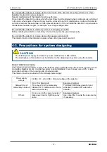
Page 22: ...sures to prevent an activated contact from having influences on external device Check that there is no clogging or leak in the connected tube If the connected tube is clogged pressure is applied to th...

Page 23: ...completed perform a gas calibration 5 3 How to start the detector Before supplying power 24 VDC to the detector check that the detector is installed properly Supply power 24 VDC to the detector turn o...

Page 24: ...ied The required warm up powered time depends on the unpowered time for the sensor The time shown in the table shown below must be met Unpowered time Guidelines for warm up powered time 24 hours or le...

Page 25: ...djustment 2 2 Perform the span adjustment Zero Span Initialization 2 3 Initialize zero span values Environmental Setting 2 4 Used for various environmental settings 2 4 0 Sensor Power Supply ON OFF 2...

Page 26: ...on mode in ten hours 5 5 User mode Detection Mode Press the MENU ESC key for three seconds User Mode 1 0 ROM SUM Display Show the program version and others This is not typically used by the user 1 1...

Page 27: ...he zero calibration failed since the zero point was significantly fluctuated from around zero it returns to 1 1 after FAIL rather than PASS is displayed In this case the zero adjustment has not been c...

Page 28: ...terminal of the detector If the alarm contact is energized option it is activated when the detector is turned OFF Setting Display 1 2 Show various setting values 5 6 How to exit To turn off the detec...

Page 29: ...entration Display In case of over the detection range Over Scale is displayed on the LED Power Indicator Lamp POWER Green During operation this lights up continuously Alarm Indicator Lamp ALM Red It l...

Page 30: ...ain valve of the gas and then check that the gas concentration reading dropped Access the gas leak point equipped with a protective gear to avoid dangers caused by possibly remaining gases and check w...

Page 31: ...1 25 sq Maximum 1 km Connection Load Resistance Below 300 1 Detection Mode No Alarm 4 20 mA concentration output 2 Detection Mode Gas Alarm 4 20 mA concentration output 3 Initial Clear Depending on th...

Page 32: ...eading Therefore the reading might be fluctuated around zero even in a normal environment This function obscures influences by environmental changes and interference gases around zero that have no mea...

Page 33: ...ntain the performance as a safety unit Maintenance item Maintenance content Daily maintenance Monthly maintenance Regular maintenance Power Supply Check Check that the power lamp lights up Concentrati...

Page 34: ...ormalities Checks the flow rate by using an external flow meter to verify the correctness of the flow rate indicator on the detector If the flow rate is incorrect performs the flow rate adjustment Fil...

Page 35: ...for various environmental settings 2 4 0 Sensor Power Supply ON OFF 2 4 1 INHIBIT Setting 2 4 2 Alarm Setpoint Setting 2 4 3 Alarm Delay Time Setting 2 4 4 Alarm Pattern Setting 2 4 5 Zero Suppressio...

Page 36: ...P38 2 1 Zero Adjustment Perform the zero adjustment Zero Adjustment P45 2 2 Span Adjustment Perform the span adjustment Span Adjustment P46 2 3 Zero Span Initialization Initialize the zero span adjust...

Page 37: ...s Electrical Settings Display Display various electrical settings This is not used by the user 2 6 Enter the factory mode This is not used by the user 2 7 Return to the user mode rET is displayed Pres...

Page 38: ...ode If the detector remains in the alarm test mode it automatically returns to the detection mode in ten hours In the alarm test mode the gas concentration equal to the reading is output even in the m...

Page 39: ...ed by a gas test even in the maintenance mode depending on setting be careful to perform the test Gas Test 2 0 0 2 0 0 Press SET key Introduce the test gas and perform the gas test Stop introducing th...

Page 40: ...epending on setting be careful to perform the test Alarm Test 2 0 1 2 0 1 Press SET key Perform the gas alarm test by increasing or decreasing the reading with the or key Press the MENU ESC key to can...

Page 41: ...ON and press the SET key to trigger the fault alarm Return to OFF and press the SET key to cancel the test Pressing the MENU ESC key also enables to cancel the test and to go back to the original sta...

Page 42: ...the RAM fault and F RO is displayed for the ROM fault For both the RAM fault and ROM fault F RA and F RO are displayed alternately 2 0 4 Press SET key When StA is displayed press the SET key again Wh...

Page 43: ...ET key to confirm the selection When ON is selected in the detection mode InHI and 0 0 gas concentration value are displayed on the LED alternately As a result an alarm is not triggered to external de...

Page 44: ...rder If they are performed in a wrong order or only one of them is performed accurate gas detection cannot be ensured 7 3 Gas calibration method Perform a gas calibration in each mode zero adjustment...

Page 45: ...wait until the indicator is stabilized NOTE If the zero calibration failed since the zero point was significantly fluctuated from around zero it returns to 2 1 after FAIL rather than PASS is displayed...

Page 46: ...If there are mistakes perform the span adjustment again If the span adjustment cannot be performed even when there is no mistake or after recalibration the gas sensor life might have expired After tu...

Page 47: ...quest it to RIKEN KEIKI Replacement of Regular Replacement Parts List of recommended regular replacement parts No Item Maintenance intervals Replacement intervals year Quantity pieces unit 1 Rubber se...

Page 48: ...r the following environmental conditions In a dark place under the normal temperature and humidity away from direct sunlight In a place where gases solvents or vapors are not present 8 2 Procedures to...

Page 49: ...Take measures such as checking or adding the UPS power supply line filter and insulation transformer The power cannot be turned on Cable abnormalities open circuit not connected short circuit Check t...

Page 50: ...IKEN KEIKI Disturbance by noise Turn off and restart the detector If such a symptom is observed frequently take appropriate measures to eliminate the noise A gas alarm is triggered despite of no gas l...

Page 51: ...t alarm self diagnosis System abnormalities sensor abnormalities Fault alarm display FAULT lamp on yellow detail display Fault alarm pattern Auto reset Alarm contact No voltage contact 1a de energized...

Page 52: ...act No voltage contact 1a de energized energized in response to an alarm or energized de energized in response to an alarm Contact capacity 250 VAC 0 5 A 30 VDC 0 5 A resistant load Transmission syste...

Page 53: ...etection principle Semiconductor Type Metal dioxide can measure gas concentration based on changes in the electric conductivity of semiconductor caused by gas adsorbed on its surface RL Load resistanc...

Page 54: ...it LEL of the combustible gas to be detected is set to 100 ppm A concentration unit that means part per million of the combustible gas to be detected Calibration Adjusts the readings to the calibratio...

Page 55: ...for removal or replacement costs local repair costs transportation costs or contingent expenses incurred without our prior approval THIS WARRANTY IS EXPRESSLY IN LIEU OF ANY AND ALL OTHER WARRANTIES...

Reviews: