background image

Summary of Contents for Mirai 24

Page 1: ......

Page 2: ...2 www rinnai it ...

Page 3: ...rtificato dalla Japan Gas Appliances Inspection Association JIA QA Center The Rinnai condensing gas wall hung combi boilers room sealed type C forced flue or open chamber type B forced flue are CE marked as allowed by Technigas Mirai 24 REB KA2024FF Mirai 29 REB KA2529FF Mirai 34 REB KA3135FF Certificate nr E1418 5657 2009 142 EC E4418 5657 92 42 EEC ID number 0461CQ1037 Date of issue 22 12 2015 D...

Page 4: ... the use and the maintenance This manual contains technical information on how to install the Rinnai boiler For other issues related to the installation comply with the laws in force and technical standards According to legislation in force the systems must be designed by qualified technicians Installation and maintenance must be performed in compliance with the regulation in force according to th...

Page 5: ... in connection with the replacement of a product or heat exchanger If Rinnai determines that repair of a product is not possible Rinnai will replace the product with a comparable product at Rinnai s discretion If a component or product returned to Rinnai is found to be free of defects in material or workmanship or damaged by improper installation the warranty claim may be denied HOW DO I GET SERVI...

Page 6: ...THE BOILER 29 DIMENSIONS 29 MAIN COMPONENTS 30 GENERAL SCHEME AND OPERATION PRINCIPLES 31 INSTALLATION 32 WATER CONNECTIONS 32 GAS CONNECTION 33 ELECTRICAL CONNECTION 33 REMOTE CONTROL 34 OUTDOOR TEMPERATURE SENSOR 35 ROOM THERMOSTAT different brand 35 FLUE SYSTEM 36 RECIRCULATION PUMP 39 HEATING SYSTEM FILLING 40 COMMISSIONING THE BOILER 41 ANTIFROST PROTECTION 42 MAINTENANCE INSTRUCTIONS 43 SERV...

Page 7: ...www rinnai it 7 The following section provides instructions for proper use of the product This section is intended for the use by qualified technical personnel and end users USER S INSTRUCTIONS ...

Page 8: ...scalding Hot water at 60 C can severely burn a child in less than a second At 50 C it takes five minutes Always test the temperature of the water before bathing or showering Do stay with children whenever they are in the bathroom Do make sure that the tap is turned off tightly Do consider setting your hot water production at a maximum temperature of 50 C Indicates a potentially hazardous situation...

Page 9: ...installed and in good condition Do not touch the flue pipe of the boiler when operating Burns can occur In case of unusual noise vibration or smell stop the boiler and contact the Rinnai service for further information ATTENTION The boiler should be installed by qualified personnel only Check the main gas valve to make sure it is opened before using the boiler and check the gas pressure is correct...

Page 10: ...filling the pipes with water and during normal use FROST PROTECTION Make sure that the power cord of the boiler is plugged in and the electrical power is always available the frost protection activates only when the boiler is electrically powered and switched ON Keep the main gas valve the heating system valves and the boiler valves open even if the boiler is not used for some days All pipes must ...

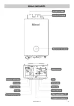
Page 11: ...www rinnai it 11 MAIN COMPONENTS ...

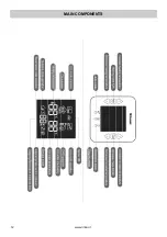
Page 12: ...12 www rinnai it MAIN COMPONENTS ...

Page 13: ...h its own remote controller only or together with any other room thermostat optional Thanks to the standard Rinnai remote controller the user can switch the CH mode on off and adjust the flow or the room temperature switch the DHW mode on off and adjust the hot water temperature activate special functions quick heating DHW pre heating auto mode etc check malfunctions and error codes check service ...

Page 14: ...d to activate it The display shows the set room temperature available temp 5 40 C in space heating mode the set flow temperature available temp 50 80 C in flow temperature mode To check and display the real room or flow temperatures they can be different from the set values push the Auto button for 2 sec actual flow temperature is displayed or push one of the arrow buttons 2 shortly actual room te...

Page 15: ...ler fires and operates 2 Press both arrow buttons on the remote 2 The boiler automatically operates at maximum power for 25min After 25min the normal operation is restored To turn off the fast heating function push one or both the arrow buttons 2 on the remote controller The fast heating function can be used to increase rapidly the appropriate room temperature in a cold place ...

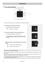
Page 16: ...uest detected blinking the burner of the boiler is ON Hot water is produced instantaneously with Rinnai boiler you will never remain without hot water as long as electric power water and gas are supplied Prior to use after installation or if the boiler has not been used for a long time let the hot water flow for a while before using The boiler is provided with a sensor that measures the hot water ...

Page 17: ...ay will show the red symbol the DHW pre heat function is available The boiler will maintain the DHW circuit heated for 30min After the first use of DHW this function is turned off automatically After 30min even if DHW was not used the boiler turns this function off for energy saving To turn off this function push both the arrow buttons 2 on the remote controller The DHW pre heat function allows a ...

Page 18: ...ode is on the boiler automatically changes to Outgoing mode When this mode is active the blue symbol showed on the left is automatically displayed on remote The Auto mode is designed to control the boiler according to the outdoor temperature Outdoor temperature is periodically measured by a thermistor and the boiler adjusts both CH and DHW set temperatures during the cold season the flow temperatu...

Page 19: ...ed Every 4 hours if the temperature in the CH circuit has dropped below 25 C the boiler switches on the CH mode for 10min at a flow temperature of 50 C If the button is pressed several times it si possible to select longer periods of CH suspensions up to 12 hours or deactivate the function at the end of this period just one cycle not repeated the boiler turns on automatically and operates at the s...

Page 20: ...ation mode is activated the boiler operates with an ON OFF cycle loop until deactivation By pushing the Reservation button one or more times the OFF period can be extended up to 12hours The default ON period is fixed at 60min and it cannot be modified During ON period the boiler operates at the CH pre set temperature The reservation mode can be suitable for mild seasons or at night if properly cus...

Page 21: ...he case of the remote controller or the wiring of the remote are damaged Push the button to switch on the boiler with the following fixed settings CH system flow temperature 52 C DHW temperature 40 C It is not recommended to use the switch during normal operation In case of a remote controller failure activate the switch not to remain without heating and hot water call immediately Rinnai service t...

Page 22: ...H RETURN FILTER When the CH return filter is clocked up it is necessary to perform maintenance cleaning it A sensor will advise if this maintenance is required on the display of the remote the symbol will start blinking 1 Unplug the boiler and wait until it is cold 2 Close the heating system flow and return valves and pull the pressure relief valve pay attention as the water could still be hot and...

Page 23: ... to the left Do not use any metal instruments because the screw top could be damaged Help yourself using a 5c coin to remove the filter 4 Once the filter has been removed wash and clean it carefully making sure not to damage the filter mesh and the screw tap o ring Reassemble the components following the previous points backwards 5 Activate the boiler pushing the buttons or ATTENTION after the cle...

Page 24: ...24 www rinnai it BASIC TROUBLESHOOTING When the boiler doesn t operate properly check the troubleshooting chart below before contacting the Rinnai service ...

Page 25: ...y to check their own operation continuously If a fault occurs an error code will flash on the digital display This assists with diagnosing the fault and may enable you to overcome a problem without a service call Please quote the code displayed when enquiring about service ...

Page 26: ... happens the display shows two couples of numbers flashing on the left is shown the error code number on the right is shown the boiler model reference see below table To reset the error code it is necessary to press and keep pressed one of the two buttons or ...

Page 27: ...ww rinnai it 27 The following section provides specific instructions for proper installation of the product This section is intended for the use by qualified technical personnel INSTALLER S INSTRUCTIONS ...

Page 28: ...gainst rain snow etc All pipes must be wrapped with appropriate insulating materials to prevent freezing and the boiler must be powered and gas fuelled also ensure that the flue system is properly connected and sealed against infiltrations The allowed temperature range are 20 C 40 C always provide a good aeration in the installation room do not install the boiler in any place affected by fire haza...

Page 29: ... or you have doubts do not install the boiler and contact your supplier or Rinnai immediately for further information Together with the boiler in the packaging you can find the following electrical wire to connect a secondary external pump DANGER keep the small parts in the packaging out of reach of children ATTENTION dispose of packaging parts appropriately after use DIMENSIONS ...

Page 30: ...30 www rinnai it MAIN COMPONENTS ...

Page 31: ...www rinnai it 31 GENERAL SCHEME AND OPERATION PRINCIPLES ...

Page 32: ...pes deeply and let the water flow to remove all the impurities After connection of the DHW system let water to flow through the boiler before the use Provide for an appropriate water treatment system to prevent lime scaling Heating circuit Heating connections are 20A male type PT3 4 Provide for the installation of an appropriate system to collect and drain water from the pressure relief valve to p...

Page 33: ...e and could cause malfunction or product failure The gases in the mixture could become stratified during storage causing the variation of the fuel calorific value and altering the boiler efficiency ELECTRICAL CONNECTION ATTENTION connect the boiler to a 230V 10 50Hz power supply Make sure that the electrical system is provided with an appropriate grounding otherwise the boiler could be severely da...

Page 34: ...al and advanced Rinnai remote controllers compatible with your boiler contact Rinnai The Rinnai remote controller must be installed on an accessible wall at 1 2 1 5m from the floor in a significant location within the house especially if it is used as a room thermostat in Space heating mode Do not install it in places where temperatures are 40 C or 20 C neither in very humid locations The remote c...

Page 35: ... thermostat other brand has been installed Room thermostat installation different brand Prior to install the device unplug the boiler loosen the two latches in the upper part of the front panel of the boiler and unscrew the two screws at the bottom remove the front panel carefully to preserve the pressure gauge lift up the panel and then separate it from the boiler remove the PCB protection cover ...

Page 36: ...e boiler FOT KS080 001 Extension Kit L 1000mm Ø80mm FOT KS080 004 2x45 bend Kit Ø80mm FOT KS080 005 1x90 bend Kit Ø80mm FOT KS080 007 Horizontal flue kit 1x90 bend L 750mm extension pipe wall flue terminal Ø80mm FOT KS080 001 FOT KS080 004 FOT KS080 005 FOT KS080 007 Flue system installation ATTENTION prior to assemble the flue system make sure that each part is not damaged install intact parts on...

Page 37: ...mple is possible as long as the previous prescriptions and conditions are respected Type B open chamber forced flue application Note in outdoor installations of the boiler under the direct action of elements rain snow etc make sure that the inlet flue system is protected against any possible infiltration of rain Type C room sealed forced flue application ...

Page 38: ...38 www rinnai it INSTALLATION Type C room sealed forced flue application ...

Page 39: ...er the PCB of the boiler activates deactivates the external pump according to the normal operation of the boiler CH antifrost protection deaerating cycle etc Installation unplug the boiler install the pump into the CH system connect the secondary pump wire supplied to the boiler s PCB the cable is supplied with a specific label identifying it remove the connector from the free end of the wire and ...

Page 40: ...the cap is open Open the venting valves on the heating system to purge the air until only water flows out ATTENTION when plugging in the boiler an automatic venting program is always activated It lasts 60 to 120 minutes and it stops automatically During this process some safety tests are also performed It is recommended not to push any button on the remote controller some symbols can appear and or...

Page 41: ...aller must refer to the national and local regulations in force In particular for the new systems open the doors and the windows to ventilate the room avoid the presence of flames and sparks properly purge the gas system from air and check for any leakage on the gas pipes according to national and local regulations Hereby are reported some general inspections ...

Page 42: ...water drops to 2 C or the installation room temperature drops to 5 C The antifreeze protections are available only if the boiler is supplied with the proper gas amount and it is power plugged the boiler is switched on and powered the boiler is not blocked error code the boiler is not damaged If the previous conditions are satisfied the appliance is frost protected until 20 C temperatures Whenever ...

Page 43: ...www rinnai it 43 MAINTENANCE INSTRUCTIONS The following section provides specific instructions for proper maintenance of the product This section is intended for the use by qualified technical personnel ...

Page 44: ...ss the DHW button on the remote 3 Push the buttons in the correct order waiting 1 2sec between them and make sure that the CH and the DHW functions are disabled If the service mode is activated the symbol of a wrench appears in lower part of the display The number shown on the left side of the display refers to the parameter selected On the right side of the display is shown the current setting of...

Page 45: ...ate Param 06 Default setting ON When the parameter is ON the boiler capacity is limited in CH value the model M34 is reduced to CH value of M29 model the model M29 is reduced to CH value of M24 model No change is operated on M24 model Param 07 Default setting 3min This parameter allows to change the waiting time of the 3 way valve before reverting back the circuit to CH after DHW use Param 10 Defa...

Page 46: ...h the buttons in the correct order waiting 1 2sec between them and make sure that the CH and the DHW functions are disabled When Fault history mode is available the white number on the left side of the display indicates the chronological error code order 01 is the most recent while the number on the right side shows the error code The lower part of the display in orange reports the total number of...

Page 47: ... meaning Below the SW1 are located three different coloured leds Their meaning is as follow ATTENTION to make any change of dip switches effective on the SW1 it is necessary to set nr7 nr8 to ON position before of any other dip switch change After the modifications to dip switches nr1 5 on SW1 turn the switches nr7 nr8 back to OFF position the new parameter changed can be verified by using the led...

Page 48: ...amper of the burner change verify and adjustment of the min and max gas pressures in DHW mode 1 Turn off the gas supply and unplug the boiler 2 Remove the front panel and the siphon 3 Check that the gas selected through dip switches of SW1 is matching with the gas supplied to the boiler NOTE a specific procedure must be followed to make the modifications effective refer to Dip switch setting parag...

Page 49: ... the bottom of the gas valves to reach the screw it is necessary to remove the rubber cap at the bottom of the casing refer to the DHW parameters When the pressure value is modified remember to seal the screw in the new position 10 Set the SW2 dip switches right block forcing the boiler at max combustion rate 11 Check the max gas pressure and adjust it according to the parameters reported into Com...

Page 50: ...essure gauge lift up the front panel first and then separate it from the boiler CONDENSATE SIPHON 1 Unplug the boiler 2 Remove the front panel 3 Disconnect the pressure gauge and detach the condensate pipes 4 Remove the fixing screws 3x and the electric connectors from the siphon PCB 1 Unplug the boiler 2 Remove the front panel and the siphon 3 Remove the plastic cover of the PCB and disconnect al...

Page 51: ...ES 1 Unplug the boiler 2 Remove the front panel the siphon and the PCB 3 Remove the manifold refer to the Gas conversion and pressure adjustment paragraph 4 Unplug the electrical wiring of the gas valves 5 Remove the clip fastening the gas duct to the coupling in the bottom part of the boiler 6 Pull out the gas valves see the drawing on the side and make sure not to damage the coupling o ring ...

Page 52: ...elief valve 2 Remove the front panel and the siphon 3 Unplug the pump wirings 4 Remove the fixing screws 2x at the bottom part of the casing 5 Remove the CH pipe clips and the pump clip 3 WAY VALVE 1 Unplug the boiler close the inlet and outlet water valves and drain the water from the CH pipes act on the pressure relief valve 2 Disconnect the CH return connector 3 Separate the CH return connector...

Page 53: ...g the boiler close the inlet and outlet water valves and drain the water from both CH and DHW pipes 2 Remove the front panel the siphon the PCB the 3 way valve and the pump 3 Disconnect the flow O ring P10 and return O ring P20 connectors of the CH pipes 4 Disconnect the inlet O ring P16 and outlet O ring P14 connectors of the DHW pipes 5 Remove the fixing screws from the heat plate exchanger EXPA...

Page 54: ...rom the heat exchanger 6x 5 Unplug the electrical wiring and sensors SECONDARY HEAT EXCHANGER 1 Unplug the boiler close the inlet and outlet water valves and drain the water from both CH and DHW pipes 2 Remove the front panel the siphon the PCB the manifold the combustion fan and the main heat exchanger 3 Disconnect the CH the condensate drain and the expansion vessel pipes from the heat exchanger...

Page 55: ...www rinnai it 55 WIRING DIAGRAM ...

Page 56: ...56 www rinnai it DIAGNOSIS POINT ...

Page 57: ...www rinnai it 57 TECHNICAL DATA ...

Page 58: ...58 www rinnai it TECHNICAL DATA Values tested with G20 20mbar gas gross calorific value Hs according to Reg UE 813 2013 ...

Page 59: ...www rinnai it 59 COMBUSTION PARAMETERS ...

Page 60: ...60 www rinnai it PRODUCT FICHE Values tested with G20 20mbar gas gross calorific value Hs according to Reg UE 811 2013 ...

Page 61: ...www rinnai it 61 DATA PLATE ...

Page 62: ...62 www rinnai it CE CERTIFICATE ...

Page 63: ...www rinnai it 63 ...

Page 64: ...ina di Quartirolo 2b 41012 Carpi MO Italia Tel 39 059 622 9248 Fax 39 059 622 4449 E mail info rinnai it Web www rinnai it V 1 160122 U306 1722X02 00 This edition replaces any previous Installation and user manual published ...

Reviews: