background image

Digital Multimeters

RISHABH  410

User Manual

RISHABH 410             

Multimeter


Summary of Contents for 410

Page 1: ...Digital Multimeters RISHABH 410 User Manual RISHABH 410 Multimeter ...

Page 2: ......

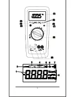
Page 3: ...1 3 4 5 6 7 8 2 1 400 mA 2 4 3 5 7 8 9 6 1 ...

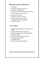
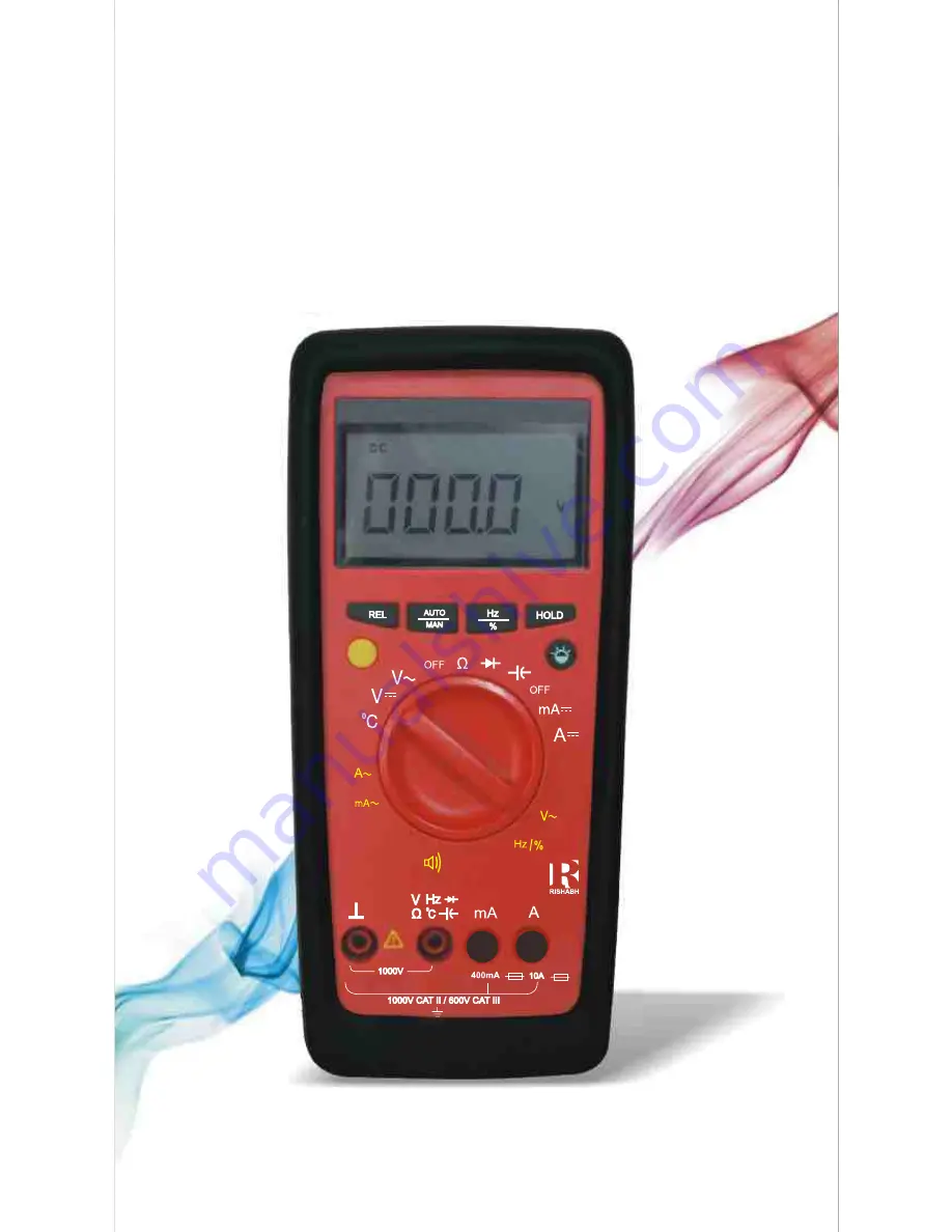
Page 4: ...Multimeter Operating Elements Data HOLD Pushbutton Backlight Pushbutton optional 8 9 Terminal Sockets LCD Display 2 Hz Pushbutton for VAC VDC ...

Page 5: ...surement 8 0 Voltage Measurement 9 0 Current Measurement 9 1 AC Measurement with Clip on C T 10 0 Diode Testing Continuity Measurement 10 1 Diode Testing 10 2 Continuity Testing 11 0 Resistance Measurement 12 0 Capacitance Measurement 13 0 Frequency Duty cycle Measurement 13 1 Frequency Measurement 13 2 Duty Cycle Measurement 14 0 Temperature Measurement 15 0 Specifications 16 0 Maintenance 16 1 B...

Page 6: ...1000 V 4 ...

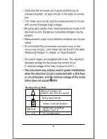
Page 7: ...ing of the symbols CAT II III Warning of a danger point Attention refer to the user manual Earth ground terminal Double or reinforced insulation Instrument for over voltage category II III or IV EU conformity mark 5 ...

Page 8: ...6 ...

Page 9: ...white or yellow print white half circle is reactivated color 7 ...

Page 10: ...AC 8 ...

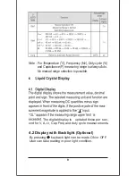
Page 11: ... is always Auto No manual range selection is possible The digital display is updated thrice per sec 4 2 Display with Backlight Optional By pressing User can take reading in poor light condition key back light can be made ON or OFF 9 ond for V A W Cap Freq and duty cycle measurements ...

Page 12: ... 400 0 mA AC DC A 10 A the buzzer will keep sounding as the overload warning Approximate 1 minute before the meter is auto power off the buzzer will raise constantly 5 sounds to warning Before the meter is power off the buzzer will raise one long sound to warn the user Hz Backlight 10 ...

Page 13: ...DC 400 mA 11 ...

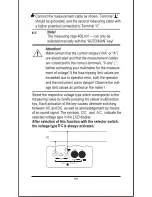
Page 14: ...After selection of this function with the selector switch the Current type DC is always activated 6 12 ...

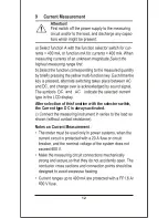
Page 15: ...6 400 mA 13 ...

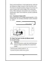
Page 16: ...10 Diode Testing Continuity Measurement 10 1 Diode Testing 400 mA 14 ...

Page 17: ...10 2 Continuity Testing OL 400 mA 15 ...

Page 18: ...11 Resistance Measurement 400 mA 400 mA 16 ...

Page 19: ...Deleting Zero Adjustment Short the leads connected to meter and then press REL key or Activate the function selector switch or Switch the Multimeter off 400 mA 17 ...

Page 20: ...18 ...

Page 21: ...le Measurement With duty cycle measurement we can determine the ratio of pulse duration to cycle time of recurring square wave signals The duty cycle that is the percentage pulse duration of signal is displayed on LCD i e Duty cycle pulse duration cycle duration X 100 Note The applied frequency must remain constant during the duty cycle measurement Set the function selector switch to VAC and press...

Page 22: ...o 1300 C 0 Set the function selector switch to C Connect the sensor as shown below Connections are made the same way as for Voltage measurement measuring range for duty cycle and maximum allowable voltage can be found in chapter Specifications V K type sensor Press Hz key Press Hz key Press Hz key Press Hz key 400 mA 400 mA 20 ...

Page 23: ...0nF 5 000m F 50 00m F 200 0m F 100mW 1W 10W 100W 1kW 10kW 100mW 1mV 1pF 10pF 100pF 1nF 10nF 100nF 10 000Hz 100 00Hz 1 0000kHz 10 000kHz 100 00kHz 500 0kHz 0 001Hz 0 01Hz 0 1Hz 1Hz 10Hz 100Hz 2 0 98 0 0 1 V AC V DC 20MW 11MW 10MW 10MW 10MW 11MW 11MW 10MW 10MW 10MW Approx Voltage drop at max meas current 450mV 4 2V 750mV 450mV 4 2V 750mV Open circuit voltage approx 0 45V approx 1V 10Hz 10Hz 10Hz 10H...

Page 24: ... 500V DC AC rms 10 min 500V DC AC rms Continuous 10 min 10 min 1kHz 1000V 10kHz 400V 500kHz 40V except 400mV 500V DC AC rms Measuring Range 400 0mV 4 000V 40 00V 400 0V 1000V 400 0mV 4 000V 40 00V 400 0V 1000V Digital display inherent deviation at reference conditions of rdg digits 0 75 2 0 5 2 1 5 5 1 5 1 10 1 Overload capacity Overload value Overload duration 1050V DC 1050V AC rms Continuous Con...

Page 25: ...5 58 23 31 4 ...

Page 26: ...24 Intrinsic ...

Page 27: ...25 ...

Page 28: ...6 6 Simply unscrew the battery compartment cover from base housing No need to remove whole base housing 26 ...

Page 29: ...ecifications may place the operator the system measuring instrument in danger The use of repaired fuses or short circuting of the fuse holder is prohibited Screw the battery compartment cover to base housing Screw the base housing cover to front housing Unscrew the base housing cover from front housing 27 ...

Page 30: ...6 28 7 ...

Page 31: ......

Page 32: ...ithout Notice Factory F 31 MIDC Satpur Nashik 422 007 India Phone 0253 2202202 2202162 Fax 91 0253 2351064 2202302 E mail International exp marketing rishabh co in RISHABH INSTRUMENTS PVT LTD Item Code 15001309 Rev A 23 7 2013 India marketing rishabh co in ...

Reviews: