
ACHTUNG!
Montage von
Schaltschrank-Kühlgeräten
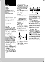
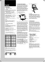
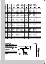
Bei der Montage ist zu beachten, daß
Warmluftein- und Kaltluftaustritt nicht zu
verbauen sind. Eine ungehinderte Luft-
zirkulation im Innenkreislauf ist zu ge-
währleisten. Ein Abstand zu den Luft-
aus- und -eintrittsöffnungen von 200 mm
bis zur Installation ist einzuhalten. Wird
das Gerät vom Netz getrennt, darf ein
erneutes Einschalten erst nach einer
Wartezeit von > 5 min. erfolgen.
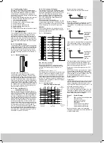
Einsatz von Türpositionsschaltern
bei Kühlgeräten
Serie .100 / .140: Die o.g. Wartezeit muß
z.B. durch die Verwendung eines
Zeitrelais sichergestellt werden.
Serie .500 / .540: Die o.g. Wartezeit wird
durch den integrierten Microcontroller
sichergestellt. Pro Gerät ist ein
potentialfreier Türpositionskontakt zu
verwenden; es dürfen auf keinen Fall
mehrere Geräte über einen Türend-
schalter betrieben werden.
In Umgebungen mit erhöhter elektro-
magnetischer Störung muß eine
geschirmte Leitung verwendet werden.
Der Türkontakt ist über zusätzliches
Relais, das in der Nähe des Gerätes pla-
ziert ist, zu schalten. Die Leitungen sind
getrennt von den Netzleitungen zu ver-
legen. Auf kurze Leitungswege achten!
Einsatz von Motor- bzw.
Trafoschutzschaltern bei Kühlgeräten
Drehstromgeräte sind über einen
Motorschutzschalter an ein TN-Netz mit
geerdetem Sternpunkt anzuschließen.
Beim Einsatz von Schaltschrank-Kühl-
geräten der Serie .140 / .540 mit
Transformatoren und Geräten in Sonder-
spannung, die ebenfalls mit Trafo
ausgerüstet sind, sind normale Motor-
schutzschalter von ihrer Einschalt-
charakteristik nicht mehr ausreichend.
Deshalb müssen kundenseitig Trafo-
schutzschalter installiert werden. Diese
sind auf den auf dem Typenschild
angegebenen Nennstrom einzustellen.
ATTENTION!
Installation of cooling units
Please make sure during installation that
warm air inlet and cold air outlet are not
obstructed. An unobstructed air circu-
lation in the inside circuit has to be
ensured. A distance of 200 mm from air
inlet and air outlet openings to the
installed equipment should be
respected. After disconnection of the
cooling unit, waiting period of > 5 min.
before reactivation.
Use of door operated switch with
cooling units
Series .100 / .140: The mentioned above
waiting period has to be ensured by
using a time relay.
Series .500 / .540: One potential-free
door operated contact has to be used
per unit, never operate more than one
unit via one door operated switch. In
environments with high electromagnetic
interference a shielded cable has to
be used. The door contact is to be
connected via an additional relay, which
is placed near the unit. The cables and
the supply line are to be laid separately.
Please ensure that the cables are as
short as possible.
Use of motor or transformer
protection switch with cooling units
Three-phase devices are to be
connected via a motor protection switch
to a TN network with earthed neutral. If
units of series .140 / .540 are used with
transformers and units with special
voltage, also equipped with transformer,
standard motor protection switches are
not sufficient due to their closed cricuit
condition. That is why transformer
protection switches have to be installed
by the customer, and have to be
adjusted to the rated current on the type
plate.
ATTENTION!
Montage des climatiseurs
d’armoires électriques
Veiller lors du montage à n’obstruer ou
gêner ni l’entrée de l’air chaud ni la
sortie de l’air froid. L’air doit pouvoir
circuler librement dans le circuit
intérieur. Respecter un écartement de
200 mm entre l’appareil installé et les
ouvertures d’entrée et de sortie d’air.
Lorsque l’appareil a été coupé du
secteur, attendre au moins 5 minutes
avant de le remettre en circuit.
Utilisation d’un interrupteur de porte
avec les climatiseur
Séries .100 / .140: La durée d’attente
mentionnée plus haut sera assurée en
installant un relais retardeur.
Séries .500 / .540: Utiliser un interrupteur
de porte sans potentiel pour chaque
appareil. Ne jamais faire fonctionner
plusieurs appareils avec un seul
interrupteur de porte.
Lorsque le milieu ambiant est soumis à
d’importantes interférences électro-
magnétiques, utiliser un câble avec
contacteur de protection. Monter le
contact de la porte avec un relais
supplémentaire placé à proximité de
l’appareil. Lors de la pose des conduc-
teurs, veiller à les séparer des lignes
d’alimentation et choisir la voie la plus
courte.
Utilisation d’un contacteur-disjoncteur
ou disjoncteur de protection pour
transformateur dans les climatiseurs
d’armoires électriques
Les appareils à courant triphasé doivent
être connectés par un contacteur-
disjoncteur au réseau TN avec neutre
mis à la terre. Dans le cas des climati-
seurs d’armoires électriques des séries
.140 / 540, équipés de transformateurs et
dans le cas des appareils avec tensions
spéciales également équipés de trans-
formateurs, les propriétés d’enclenche-
ment des disjoncteurs standard ne sont
pas suffisantes. Le client devra alors
prévoir des disjoncteurs de protection
pour transformateurs et les régler sur la
valeur du courant nominal indiquée sur
la plaque signalétique.
LET OP!
Montage van schakelkast-
koelaggregaten
Bij de montage dient erop te worden
gelet dat de aanzuigopeningen van de
warme lucht en de inblaasopeningen
van de koude lucht niet mogen worden
gemodificeerd. Anders kan geen
ongehinderde luchtcirculatie in het
binnencircuit worden gegarandeerd.
Tussen de luchtaanzuig-, luchtinblaas-
openingen en de installatie dient een
afstand van minimaal 200 mm te worden
aangehouden. Wordt het aggregaat van
het net gescheiden, dan mag het pas na
een wachttijd van tenminste 5 minuten
opnieuw worden ingeschakeld.
Toepassing van deurschakelaars bij
koelaggregaten
Serie .100 / .140: De hierboven genoem-
de wachttijd dient door toepassing van
bijv. een tijdrelais te worden zeker-
gesteld. Serie .500 / .540: Per aggregaat
dient één potentiaalvrij deurcontact te
worden toegepast; er mogen in geen
geval meerdere aggregaten op één
deurschakelaar worden aangesloten. In
omgevingen waar verhoogde elektro-
magnetische storingen voorkomen, dient
een afgeschermde kabel te worden
toegepast. Het deurcontact kan via een
extra relais, dat in de buurt van het
aggregaat is aangebracht, worden
geschakeld. De kabels diene geschei-
den van de netvoedingskabels te
worden gelegd. Let erop dat zo kort
mogelijke kabels worden gebruikt!
Inzet van motor respectievelijk
transformatorbeveiligingsschakelaar
bij koelaggregaten
Draaistroomaggregaten zijn via een
motorbeveiligingsschakelaar aan een
TN-stelsel met geaard sterpunt ann te
sluiten. Bij de toepassing van schakel-
kast-koelaggregaten van de serie .140 /
.540 met transformatoren en aggregaten
met afwijkende spanningen die ook
zijn voorzien van een transformator zijn
standaard motorbeveiligingsautoma-
ten niet voldoende als gevolg van hun
inschakelkarakteristiek. Daarom dienen
trafobeveiligingsschakelaars door de
klant zelf te worden geïnstalleerd en te
worden ingesteld volgens de op het type-
plaatje aangegeven nominale stroom.
VARNING!
Montering av
apparatskåpskylaggregat
Vid montering måste beaktas att
varmluftsintag och kalluftsutblås inte är
spärrade. En fri luftcirkulation inuti
skåpet måste garanteras. Utrymmet
mellan luftintag, utblåsöppningar och
installationerna måste vara 200 mm.
Efter att kylaggregatet stängts av kan
det startas först efter 5 minuter.
Användning av dörrkontakt med
kylaggregat
Vid serierna .100 / .140 måste den ovan
nämnda väntetiden åstadkommas
genom ett tidrelä.
Vid serierna .500 / .540 måste en
potentialfri dörrkontakt användas per
enhet, det får heller aldrig användas mer
än en enhet per dörrkontakt. I miljöer
med hög elektromagnetisk påverkan
måste en skärmad kabel användas.
Dörrkontakten ska kopplas via ytterligare
ett relö, vilket placeras nära enheten.
Kablage dras skiljt från nätledningen. Se
till att kablarna är så korta som möjligt!
Användning av motor- resp transfor-
matorskyddsbrytare med kylaggregat
Trefasaggregat ansluts via en
motorskyddsbrytare till ett TN-nät med
jordad nollpunkt. Om kylaggregat ur
serierna .140 / .540 används med
transformatorer och enheter med
specialspänning, även de utrustade
med transformatorer, räcker inte
standard motorskyddsbrytare beroende
på deras slutna kretsar. Därför måste
transformatorskyddsbrytare installeras,
Dessa ska ställas in på den på
typskylten angivna nätströmmen.
ATTENZIONE!
Installazione di condizionatori
Durante il montaggio accertarsi che
l’entrata aria calda e l’uscita aria fredda
non siano ostruite. Occorre assicurare la
libera circolazione dell’aria nel circuito
interno, nonchè rispettare una distanza
di 200 mm dalle aperture di entrata e
scarico aria al luogo di installazione.
Una volta disinserito l’apparecchio è
possibile riavviarlo soltanto dopo
> 5 min. di attesa.
Impiego di interruttori di posiziona-
mento porta nei condizionatori
Serie .100 / .140: il suddetto tempo di
attesa prima di riavviare l’apparecchio
deve essere rispettato utilizzando ad es.
un relais a tempo.
Serie .500 / .540: il tempo di attesa
sopra indicato viene assicurato dal
microcontroller integrato. Si deve
utilizzare un interruttore di posiziona-
mento porta per ogni apparecchio; non
è possibile in nessun caso azionare più
apparecchi con un interruttore.
In ambienti particolarmente soggetti ad
interferenze elettromagnetiche occorre
utilizzare un cavo schermato.
L’interruttore per la porta dovrà essere
collegato ad un ulteriore relais, situato
vicino all’apparecchio. I cavi e le linee
elettriche devono essere posati in sede
separata. Prevedere linee di connes-
sione con lunghezza limitata.
Impiego di interruttori di protezione
trasformatore nei condizionatori
I normalli interruttori di protezione dei
motori, per le loro caratteristiche, non
sono più sufficienti per essere impiegati
su condizionatori della serie .140 / .540
con trasformatori e apparecchiature a
tensione speciale, dotate anch’esse di
trasformatore: Il cliente dovrà quindi
installare interruttori di protezione del
trasformatore, da tarare in base al valore
della corrente nominale indicato sulla
targhetta.
¡ATENCION!
Montaje de refrigeradores
En el montaje debe tenerse en cuenta
que la entrada de aire caliente y la
salida de aire frío no se encuentren
obstruidas. Debe garantizarse una
circulación adecuada del aire en el
circuito interior. Debe mantenerse una
distancia de 200 mm entre las escota-
duras de salida y de entrada de aire
hasta el punto de instalación. Tras la
desconexión del aparato deben trans-
currir > 5 min. hasta la próxima conexión.
Uso de interruptores de posición de
puerta en refrigeradores
Serie .100 / .140: El tiempo de reposo
mencionado arriba debe garantizarse
mediante el montaje de un relé de
tiempo.
Serie .500 / .540: Debe utilizarse un
contacto libre de potencial de posición
de puerta por aparato; en ningún caso
deberá utilizarse un sólo interruptor final
para más de un aparato.
En entornos con elevada perturbación
electromagnética debe utilizarse un
cable apantallado. El contacto de
puerta debe conectarse a través de un
relé adicional situado cerca del aparato.
Los cables deben tenderse separados
de los cables de red. Procure que los
cables sean lo más cortos posibles.
Uso de interruptores de protección
de motores o de transformadores en
refrigeradores
Los aparatos de corriente trifásica
deben conectarse mediante un inter-
ruptor de protección de motores a una
red TN con toma de tierra en forma de
estrella. Con la aplicación de los refrige-
radores para armarios de las series
.140 / .540 con transformadores y apa-
ratos con tensión especial, equipados
también con transformadores, los
interruptores de protección de motor
normales son insuficientes a causa de
sus características de conexión. Por tal
motivo el cliente deberá instalar un
interruptor de protección de transforma-
dor. Estos deben ajustarse en función
de la corriente nominal indicada en la
placa de características.
GB
D
F
NL
S
I
E
J
Rittal
SK
Umschalten auf Perfektion
Umschalten auf Perfektion
Umweltorientierte
K ü h l t e c h n i k
<Umschlag A3>
7/
9
7
2. Aufl.
9/99
Rittal-Werk · Rudolf Loh GmbH & Co. KG · Postfach 16 62 · D-35726 Herborn
Telefon (0 27 72) 5 05-0 · Telefax (0 27 72) 5 05-23 19 · eMail: Info@rittal.de · Internet: http://www.rittal.de
Schaltschrank-Systeme
Enclosure systems
Systèmes d’armoires électriques
Schakelkastsystemen
Apparatskåpssystem
Sistemi di armadi per quadri di comando
Sistemas de armarios
Elektronik-Aufbau-Systeme EL
Electronic systems EL
Systèmes de montage électroniques EL
Elektronica-opbouwsystemen EL
Elektroniksystem EL
Sistemi di allestimento EL per l’elettronica industriale
Sistemas de soporte electrónicos EL
Schaltschrank-Klimatisierung SK
Enclosure air-conditioning SK
Climatisation d’armoires électriques SK
Schakelkastklimaatbeheersing SK
Apparatskåpsklimatisering SK
Apparecchi SK per la climatizzazione di quadri di com.
Climatización de armarios SK
Stromverteilungs-Komponenten SV
Power distribution components SV
Composants de distribution de courant SV
Stroomverdelingscomponenten SV
Strömfördelningskomponenter SV
Componenti SV per la distribuzione di corrente elettrica
Componentes de distribución de corriente SV
Datenübertragungs-Komponenten DK
Data communication components DK
Composants de distribution de données informat. DK
Data-overdrachtscomponenten DK
Dataöverföringskomponenter DK
Armadi e contenitori DK per trasmissione dati e telefonia
Componentes de la transmisión de datos
Outdoor-Gehäuse CS
Outdoor enclosures CS
Armoires outdoor CS
Outdoor-behuizingen CS
Utomhusskåp CS
Armadi modulari CS per applicazioni da esterno
Cajas para la intemperie CS
231233
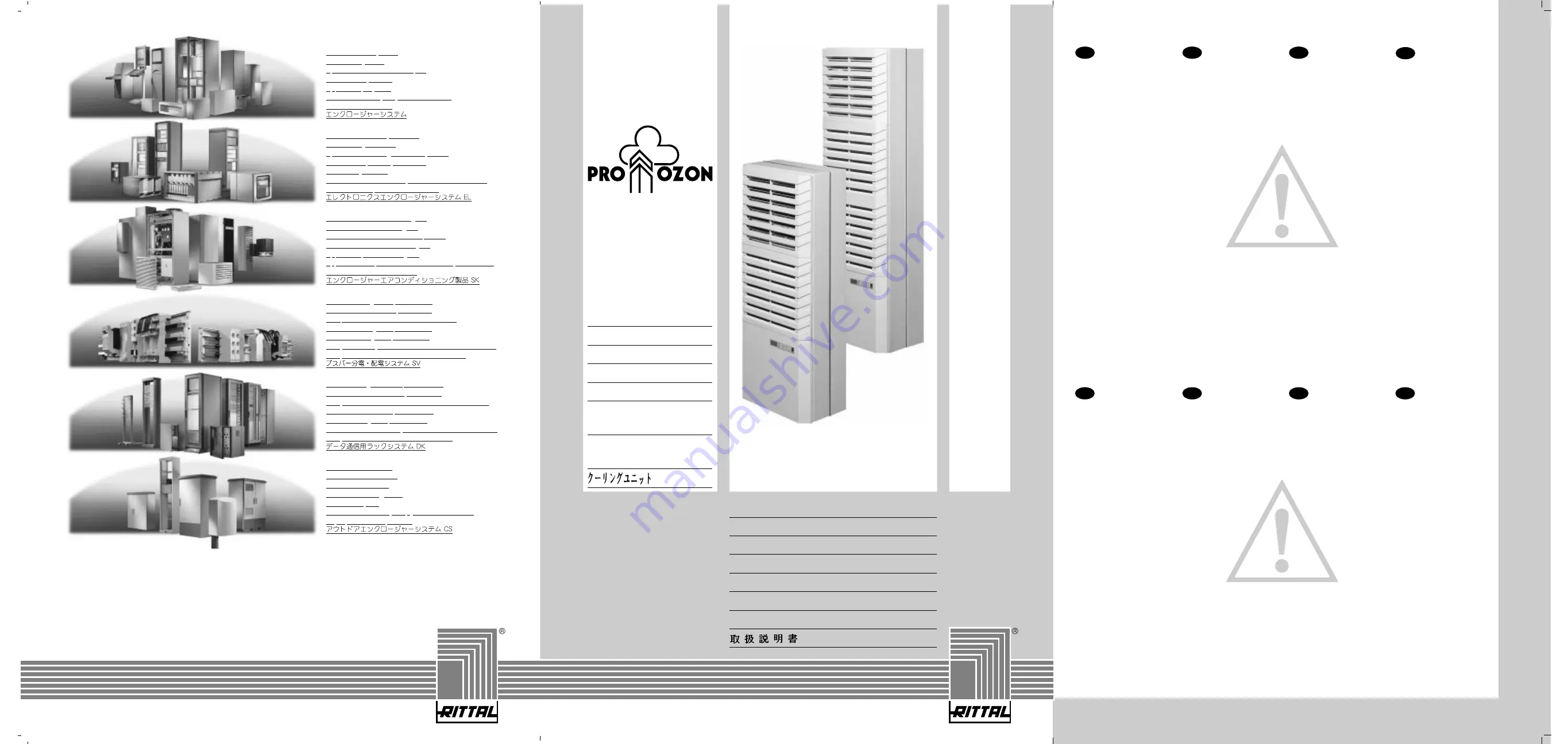
Schaltschrank-
Kühlgerät
Cooling Unit
Climatiseur
Koelaggregaat
Kylaggregat
Condizionatore
per armadi
Refrigerador
para armarios
Montageanleitung
Assembly Instructions
Notice de montage
Montage-instructie
Montageanvisning
Istruzioni di montaggio
Instrucciones de montaje
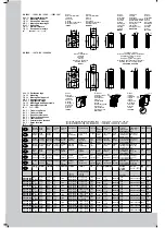
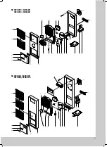
SK 3293.100
SK 3293.140
SK 3281.100
SK 3293.500
SK 3293.540
SK 3393.100
SK 3393.140
SK 3381.100
SK 3393.500
SK 3393.540
SK 3279.100
SK 3298.100
SK 3298.500
SK 3260.500
SK 3260.140


