Replacement Air Compressor
Installation Instructions
ROADMASTER, Inc. 6110 NE 127th Ave. Vancouver, WA 98682 800-669-9690 Fax 360-735-9300 www.roadmasterinc.com
ALL SPECIFICATIONS ARE SUBJECT TO CHANGE WITHOUT NOTICE
85-1840-03 04-09
1-800-669-9690
www.roadmasterinc.com
part numbers 8310 and 8315
Before you begin the installation…
This kit will replace the air compressor in BrakeMaster
8000, 9000 and 9060 systems.
These instructions assume that you will install the
replacement compressor in the same location as the
original, and also that you have removed the original
compressor, and disconnected the wiring and air line,
from a previously-installed BrakeMaster.
For complete 9000-series installation and operating
instructions visit www.roadmasterinc.com; call 800-669-
9690 for 8000-series installation and operating instructions.
These instructions pertain to the installation of the
replacement air compressor and associated compo-
nents only. Instructions for the complete system are
available online, or by calling 800-669-9690.
Read all instructions before installing or operating
this product. Failure to understand how to install or
operate BrakeMaster could result in property dam-
age, personal injury or even death.
Step One
Wire the air compressor
1.
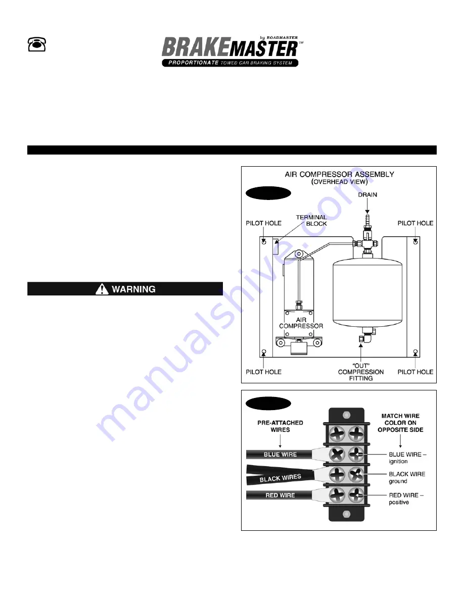
Position the air compressor so that the four pre-drilled
holes in the housing (one at each corner, Figure 1) are
aligned over the four screw holes used to attach the
original compressor.
Do not attach the air compressor now — in most cases,
it will be considerably easier to connect the wiring and
the air lines with the compressor loose.
2.
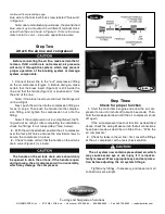
At the air compressor, use one of the small ring ter-
minals to attach the red wire to the terminal block screw
opposite the pre-attached red wire (Figure 2).
Next, use another small ring terminal to attach the
black wire to the terminal block screw opposite the pre-
attached black wires (Figure 2).
Note: due to manufacturing variances, the preattached
red and black wires may be mounted to different terminal
block screws than those shown in Figure 2. If this is the
Figure 1
Figure 2
case, match color to color — red wire opposite red wire,
and black wire opposite black wires.
3.
Next, use another small ring terminal to attach the
continued on next page


