background image

Installation Instructions

POINT I/O 5V DC and 24V DC Very High 
Speed Counter Module

Catalog Numbers 1734-VHSC5, 1734-VHSC24, Series C

Table of Contents

Topic

Page

Important User Information 

2

Environment and Enclosure

3

Preventing Electrostatic Discharge

3

North American Hazardous Location Approval

4

European Hazardous Location Approval

5

Additional Resources

6

About the Module

6

Install the Mounting Base

8

Install the Module

8

Install the Removable Terminal Block

10

Remove a Mounting Base

11

Wire the Module

12

Communicate with Your Module

13

Interpret Status Indicators

20

Specifications

22

Summary of Contents for 1734-VHSC24

Page 1: ...ment and Enclosure 3 Preventing Electrostatic Discharge 3 North American Hazardous Location Approval 4 European Hazardous Location Approval 5 Additional Resources 6 About the Module 6 Install the Mounting Base 8 Install the Module 8 Install the Removable Terminal Block 10 Remove a Mounting Base 11 Wire the Module 12 Communicate with Your Module 13 Interpret Status Indicators 20 Specifications 22 ...

Page 2: ...particular installation Rockwell Automation Inc cannot assume responsibility or liability for actual use based on the examples and diagrams No patent liability is assumed by Rockwell Automation Inc with respect to use of information circuits equipment or software described in this manual Reproduction of the contents of this manual in whole or in part without written permission of Rockwell Automati...

Page 3: ...omplying with a flame spread rating of 5VA or be approved for the application if nonmetallic The interior of the enclosure must be accessible only by the use of a tool Subsequent sections of this publication may contain additional information regarding specific enclosure type ratings that are required to comply with certain product safety certifications In addition to this publication see Industri...

Page 4: ...ettes à inspection par les autorités locales qualifiées au moment de l installation EXPLOSION HAZARD Do not disconnect equipment unless power has been removed or the area is known to be nonhazardous Do not disconnect connections to this equipment unless power has been removed or the area is known to be nonhazardous Secure any external connections that mate to this equipment by using screws sliding...

Page 5: ...s equipment is not resistant to sunlight or other sources of UV radiation WARNING This equipment shall be mounted in an ATEX certified enclosure with a minimum ingress protection rating of at least IP54 as defined in IEC60529 and used in an environment of not more than Pollution Degree 2 as defined in IEC 60664 1 when applied in Zone 2 environments The enclosure must utilize a tool removable cover...

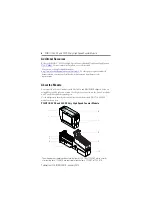
Page 6: ...Automation distributor or sales representative About the Module You can use these Series C modules with DeviceNet and PROFIBUS adapters If you are using RSLogix 5000 software version 11 or higher you can also use the Series C modules with ControlNet and Ethernet adapters Use this diagram to identify the external features of the module The 1734 VHSC5 module is shown here POINT I O 5V DC and 24V DC ...

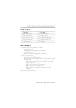
Page 7: ...s ground chas gnd and common C Module 2 connects screws 4 and 5 and screws 6 and 7 for ease of wiring power to the input device Module 2 is not necessary for VHSC functionality Module 2 serves only to ease customer wiring Module 2 does not use a node address or consume power from the POINTBus Mount module 2 adjacent to module 1 Module Description Description Description 1 Module locking mechanism ...

Page 8: ...hrough the DIN rail to chassis ground Use zinc plated yellow chromate steel DIN rail to assure proper grounding The use of other DIN rail materials for example aluminum or plastic that can corrode oxidize or are poor conductors can result in improper or intermittent grounding Secure DIN rail to mounting surface approximately every 200 mm 7 8 in and use end anchors appropriately ATTENTION Do not di...

Page 9: ...ain the DIN rail locking screw is in the horizontal position You cannot insert the module if the locking mechanism is unlocked 3 Insert the module straight down into the mounting base 4 Press to secure The module locks into place Turn the keyswitch to align the number with the notch position 3 is shown 44009 Be sure the DIN rail locking screw is in the horizontal position 44010 2 4 V D C S o u r c...

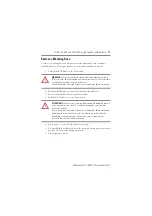
Page 10: ... the end opposite the handle into the base unit This end has a curved section that engages with the wiring base 2 Rotate the terminal block into the wiring base until it locks itself in place 3 If an I O module is installed snap the RTB handle into place on the module WARNING When you connect or disconnect the Removable Terminal Block RTB with field side power applied an electrical arc can occur T...

Page 11: ...e locking screw to a vertical position This releases the locking mechanism 7 Lift straight up to remove WARNING When you connect or disconnect the Removable Terminal Block RTB with field side power applied an electrical arc can occur This could cause an explosion in hazardous location installations Be sure that power is removed or the area is nonhazardous before proceeding ATTENTION When you inser...

Page 12: ...c can occur This could cause an explosion in hazardous location installations Be sure that power is removed or the area is nonhazardous before proceeding 0 1 0 1 Vaux Chassis ground RET 0 RET 1 Vaux Vaux Chassis ground Vaux Input Aret Input Bret Input Zret Out 1 Input A Input B Input Z Out 0 Status of output 0 Module status Network status Status of input A Status of input B Status of output 1 Stat...

Page 13: ...mes 2 or 4 Bytes of I O data scanner Tx Set parameter 25 to zero to re enable parameter 4 active output Use Parameter To Select Assembly For Data 23 and 24 101 102 or 103 Produced 25 105 106 or 107 Consumed Aret A 1 0 Bret B 3 2 Zret Z 5 4 Out 1 Out 0 7 6 Chas gnd Chas gnd 1 0 RET 1 RET 0 3 2 Vaux Vaux 5 4 Vaux Vaux 7 6 Module 1 Module 2 Module 1 Terminations Module 2 Terminations 0 A 0 Chassis gr...

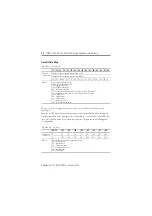
Page 14: ... Channel 0 value of present counter state LSW Channel 0 value of present counter state MSW PE EF NR 0 FS FS OS OS 0 ZS BS AS C1 C0 ZD 0 Where LSW Least significant word MSW Most significant word PE Programming error EF EEPROM fault status NR Not ready status bit FS Output fault status bit bit 10 for output 0 bit 11 for output 1 OS Output on off status bit bit 8 for output 0 bit 9 for output 1 ZS Z...

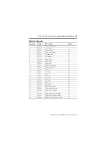
Page 15: ... 1 8 Set Get Output 0 ties 1 9 Set Get Output 1 ties 1 10 Set Get Channel rollover value 4 11 Set Get Channel preset value 4 12 Set Get ON value 1 4 13 Set Get OFF value 1 4 14 Set Get ON value 2 4 15 Set Get OFF value 2 4 16 Set Get ON value 3 4 17 Set Get OFF value 3 4 18 Set Get ON value 4 4 19 Set Get OFF value 4 4 20 Set Get PWM safe state value 2 21 Set Get Counter control safe state 1 22 Se...

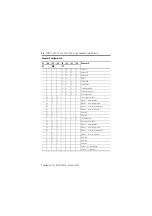
Page 16: ...0 1 1 1 Rate measurement 1 0 0 0 Pulse generator 0 0 0 Store count disabled 0 0 1 Mode 1 store continue 0 1 0 Mode 2 store wait resume 0 1 1 Mode 3 store reset wait start 1 0 0 Mode 4 store reset start 1 0 1 Reserved 1 1 0 Reserved 1 0 0 0 Pulse generator 0 0 0 Store count disabled 0 0 1 Mode 1 store continue 0 1 0 Mode 2 store wait resume 0 1 1 Mode 3 store reset wait start 1 0 0 Mode 4 store res...

Page 17: ... ms 1 25 ms 0 A input not filtered 1 A input filtered 0 B input not filtered 1 B input filtered 0 Z input not filtered 1 Z input filtered Assumes a 50 duty cycle signal Scalar Selection 07 06 05 04 03 02 01 00 Scalar 1 0 0 0 0 0 0 0 1 Z Fmin 0 149 Hz 0 0 0 0 0 0 1 0 Z 2 Fmin 0 298 Hz 0 0 0 0 0 1 0 0 Z 4 Fmin 0 596 Hz 0 0 0 0 1 0 0 0 Z 8 Fmin 1 192 Hz 0 0 0 1 0 0 0 0 Z 16 Fmin 2 384 Hz 0 0 1 0 0 0 ...

Page 18: ...ed channel data 4 Status 2 103 0x67 Get Present channel data 4 Stored channel data 4 Status 2 104 0x68 Get Programming error code 2 105 0x69 Set Get Counter control 1 Output control 1 106 0x6a Set Get PWM value 2 107 0x6b Set Get PWM value 2 Counter control 1 Output control 1 108 0x6c Set Get Counter configuration 1 Filter selection 1 Decimal position 1 Active output assembly 1 Time base or PWM pe...

Page 19: ...t Get Counter configuration 1 Filter selection 1 Decimal position 1 Reserved set to 0 1 Time base or PWM period 2 Gate interval 1 Scalar 1 Output 0 ties 1 Output 1 ties 1 Alignment reserved 0 2 Rollover value 4 Preset value 4 ON value 1 4 OFF value 1 4 ON value 2 4 OFF value 2 4 ON value 3 4 OFF value 3 4 ON value 4 4 OFF value 4 4 PWM safe state value 2 Counter control SSV 1 Output control SSV 1 ...

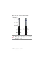
Page 20: ...ule Indicator Status for Modules Status Description Module status Off No power applied to device Green Device operating normally Flashing green Device needs commissioning due to missing incomplete or incorrect configuration Flashing red Recoverable fault Red Unrecoverable fault may require device replacement Flashing red green Device is in self test mode 0 1 0 1 Status of output 0 Module status Ne...

Page 21: ...ce detected error that prevents it from communicating on the network Flashing red green Communication faulted device the device has detected a network access error and is in communication faulted state Device has received and accepted an Identity Communication Faulted Request long protocol message Input status Off Input is inactive Yellow Input is active and under control Flashing yellow Input is ...

Page 22: ...A 15V DC 10 2 mA 24V DC Input OFF state current max 0 250 mA Input OFF state voltage 1734 VHSC5 1 25V DC 1734 VHSC24 1 8V DC Input ON state current 5 mA Input ON state voltage 1734 VHSC5 2 6V DC 1734 VHSC24 12 5V DC Maximum ON state voltage 1734 VHSC5 6V 1734 VHSC24 Refer to Input Derating Curve for 1734 VHSC24 diagram Input filter selections Off 10 μs 100 μs 1 0 ms 10 0 ms Maximum input frequency...

Page 23: ...ltage drop 0 3V DC 0 5 A ON state current 0 5 A max Pilot Duty Short circuit current 6 A Outputs are short circuit protected and either cycle until you correct the fault or latch off depending upon programming Short circuit is detected when output turns on Open wire detection Open wire is detected when output is turned off Delay time 1 OFF to ON ON to OFF 25 μs load dependent 150 μs load dependent...

Page 24: ...ystem External DC power does not represent power required to supply outputs No additional external power required to power module Field power bus nom 24V Field power bus range 10 28 8V DC Dimensions HxWxD approx 56 0 x 12 0 x 75 5 mm 2 21 x 0 47 x 2 97 in Wiring category 1 1 on signal ports Wire size 0 34 2 1 mm 22 14 AWG solid or stranded copper wire rated 75 ºC 167 ºF or greater 1 2 mm 3 64 in i...

Page 25: ...amp Heat 5 95 noncondensing Vibration IEC 60068 2 6 Test Fc Operating 5 g 10 500 Hz Shock operating IEC60068 2 27 Test Ea Unpackaged Shock 30 g Shock nonoperating IEC 60068 2 27 Test Ea Unpackaged Shock 50 g Emissions CISPR 11 IEC 61000 6 4 Class A ESD immunity IEC6100 4 2 6 kV contact discharges 8 kV air discharges Radiated RF immunity IEC 61000 4 3 10 V m with 1 KHz sine wave 80 AM from 80 2000 ...

Page 26: ... 6 2 Industrial Immunity EN 61000 6 4 Industrial Emissions EN 61131 2 Programmable Controllers Clause 8 Zone A B C Tick Australian Radiocommunications Act compliant with AS NZS CISPR 11 Industrial Emissions Ex European Union 94 9 EC ATEX Directive compliant with EN 60079 15 Potentially Explosive Atmospheres Protection n EN 60079 0 General Requirements II 3 G Ex nA IIC T4 Gc DEMKO 04 ATEX 0330347X ...

Page 27: ... 27 Publication 1734 IN003F EN E January 2014 Input Derating Curve for 1734 VHSC24 IMPORTANT Exceeding the maximum input voltage can cause permanent damage to the input Module Ambient Still Air Temperature C 10 20 24 28 8 10 20 30 40 45 50 55 Input Voltage V ...

Page 28: ...perational when shipped from the manufacturing facility However if your product is not functioning and needs to be returned follow these procedures Documentation Feedback Your comments will help us serve your documentation needs better If you have any suggestions on how to improve this document complete this form publication RA DU002 available at http www rockwellautomation com literature United S...

Reviews: