PS10 v3.2 EN Rev.C.doc
2007-10-23
1
Power Supply
Type PS10
v3.2
P
RODUCT
D
ESCRIPTION
The PS10 is dedicated for electronic equipment which require 12VDC buffered supply
source. Device consist of metal case with compartment for sealed lead-acid battery,
mains transformer and electronic circuit. PS10 may deliver up to 1.2A current without
any time limit, it utilize DC/DC “switched mode” electronic circuit which offer high
efficiency (reduced heating of electronic components). PS10 employs internal current
limiting and short circuit protection which make it essentially indestructible. The reserve
battery is connected to output terminals trough an ultra low-resistance MOS transistor,
such a circuit architecture enables optimum performance during AC failure and during
dynamic changes of load when excessive current consumption is required. PS10 charge
battery with
constant current-constant voltage
method, this method of charging
guaranties relatively quick and safe charging process. The initial charging current is
factory set to ~300mA, installer should be aware that with battery connected to PS the
output current will be reduced to 900mA. Depending on battery charging phase the
output voltage of PS10 may vary from approx. 11.5 up to 13.8V level. When battery
voltage drops below ~10.0V level internal circuit disconnect it from load, battery is
automatically reconnected when AC supply returns. Battery cut off circuit protect battery
from deep discharge but the equipment connected to power supply from operation below
10.0V level which in many cases can lead to undefined system behavior. Battery is
protected with 5A fuse which reduce maximum output current sourced from battery and
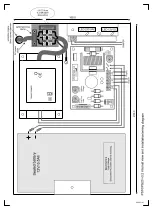
electronic circuit against battery reverse connection. PS10 offer two output ports (Z1 and
Z2 terminals). The nominal output voltage is factory set to 13.8V and should not be
changed by user. PS10 is equipped with two LEDs, the red one (marked as 230VAC)
signalize that AC power exists where the second one (marked as 12VDC) signalize that
output voltage is available.
O
PTIONAL
A
LARM
M
ODULE
PSAM-1
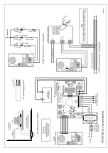
For more sophisticated installation electronic circuit of PS10 can be equipped with
optional alarm module (PSAM-1). This module can be connected to PS10 circuit through
dedicated connector (CON4) which is located on PS10 board. The main purpose of PSAM-
1 module is to signalize an alarm situation of power supply to external device or system.
The PSAM-1 may operate in autonomic or networked mode. When set to autonomic
mode it offer three transistors outputs which are dedicated to signalize following
situations:
-
low battery
-
battery failure
-
AC lost
Those outputs can be connected to external control panel, access controller or another
control or signaling device which will warn authorized personnel.
When PSAM-1 operates in networked mode it must be connected to PR series access
controller (PR302/PR402 or PR302LCD) through Clock & Data interface. In this mode
PSAM-1 module sends all messages about power supply condition direct to access
controller. During
networked
mode PSAM-1 signalize the same alarm condition as during
standalone mode and additionally delivers data about actual voltage level available on
PS’s output terminals.


