background image

Summary of Contents for SP-300i

Page 1: ......

Page 2: ......

Page 3: ... us Roland DG Corp assumes no responsibility for any direct or indirect loss or damage which may occur through use of this product regardless of any failure to perform on the part of this product Roland DG Corp assumes no responsibility for any direct or indirect loss or damage which may occur with respect to any article made using this product This product is using GNU General Public License GPL ...

Page 4: ...rounding conduc tor can result in a risk of electric shock The conductor with insulation having an outer surface that is green with or with out yellow stripes is the equipment grounding conductor If repair or replacement of the electric cord or plug is necessary do not connect the equipment grounding conductor to a live terminal Check with a qualified electrician or service personnel if the ground...

Page 5: ...atures 40 2 4 Starting Output 41 Getting Ready to Receive Data from a Computer 41 Printing Tests and Cleaning 42 2 5 If Ink Runs Out 43 Checking for Remaining Ink 43 If Ink Runs Out 43 2 6 Performing Cutting 45 To Perform Cutting 45 Performing a Cutting Test 46 Making the Setting for Blade Force 47 Chapter 3 Maintenance and Adjustment 49 3 1 Daily Care and Maintenance 50 Disposing of Discharged In...

Page 6: ...f the Sleep Mode 85 Deactivating the Sleep Mode 85 Changing the Menu Language and the Units of Measurement 86 Returning All Settings to Their Initial Values 86 4 7 Changing the Ink drying Method 87 Switching Off the Print Heater and Dryer 87 Determining How the Media Heating System Operates 87 Drying the Trailing Edge of the Printing Area on the Dryer 88 4 8 Making Various Adjustments for Cutting ...

Page 7: ...es 115 Colors Are Unstable or Uneven 115 The Media Becomes Soiled When Printed 116 Cutting Is Misaligned or Skewed 116 5 3 The Media Jams 117 The Media Jams 117 5 4 Media Wrinkles or Shrinks or Feed Is Unstable 118 Media Wrinkles or Shrinks 118 Media Feed Is Not Straight 118 Media Feed Is Not Smooth 118 5 5 The Print Heads Stopped Moving 119 What to Do First 119 If the Heads Still Do Not Move 119 ...

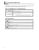
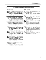
Page 8: ...pect to the home and all its furnishings as well to domestic animals or pets About the Symbols The symbol alerts the user to important instructions or warnings The specific meaning of the symbol is determined by the design contained within the triangle The symbol at left means danger of electrocution The symbol alerts the user to items that must never be carried out are forbidden The specific thin...

Page 9: ...ning maintenance or attachment or detachment of optional items disconnect the power cord Attempting such operations while the machine is connected to a power source may result in injury or electrical shock Never attempt to disassemble repair or modify the machine Doing so may result in fire electrical shock or injury Entrust repairs to a trained service technician CAUTION Exercise caution to avoid...

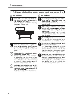
Page 10: ...be a danger WARNING Handle the power cord plug and electrical outlet correctly and with care Never use any article that is damaged Using a damaged article may result in fire or electrical shock When using an extension cord or power strip use one that adequately satisfies the machine s ratings for voltage frequency and current Use of multiple electrical loads on a single electrical outlet or of a l...

Page 11: ...nd electrical outlet Never place any object on top or subject to damage Never bend or twist with undue force Never pull with undue force Never bundle bind or roll up Never allow to get wet Never make hot Dust may cause fire To Ensure Safe Use 9 ...

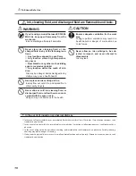
Page 12: ...e away from the work area Ink and discharged fluid are flammable Never store ink cleaning fluid or dis charged fluid in any of the following loca tions Any location exposed to open flame Any location where high temperature may occur Near bleach or any other such oxidizing agent or explosive material Any location within the reach of chil dren Fire may be a danger Accidental ingestion by children ma...

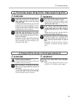
Page 13: ...topple a major accident may result including crushing of the appendages or the body When storing roll media implement ad equate safety measures to ensure that the stored media will not roll fall or topple over Danger exists of becoming pinned under the media and suffering serious injury Handling roll media is an operation that must be performed by two persons or more and care must be taken to prev...

Page 14: ...p away from open flame Caution Moving Print Heads The print heads inside the cover move at high speed and pose a hazard Never insert the hand or fingers into the gap Caution Pinching Hazard Be careful not to allow the fingers to become pinched when loading media or closing covers Caution High Temperature The platen and dryer become hot Exer cise caution to avoid fire or burns Ink Is Toxic Ink and ...

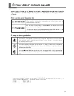
Page 15: ...tention de l utilisateur sur les instructions importantes ou les avertissements Le sens précis du symbole est déterminé par le dessin à l intérieur du triangle Le symbole à gauche signifie danger d électrocution Le symbole avertit l utilisateur de ce qu il ne doit pas faire ce qui est interdit La chose spécifique à ne pas faire est indiquée par le dessin à l intérieur du cercle Le symbole à gauche...

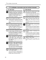
Page 16: ...l appareil et avant d y fixer ou d en re tirer des accessoires en option Tenter ces opérations pendant que l appareil est branché à une source d alimentation peut causer des blessures ou un choc électrique Ne jamais tenter de démonter de réparer ou de modifier l appareil Le non respect de cette consigne risque de provoquer un incendie un choc électrique ou des blessures Confier les réparations à u...

Page 17: ...nt se produire Risque de décharge ou de choc électrique d électrocution ou d incendie Caractéristiques ATTENTION Manipuler le câble d alimentation la fiche et la prise électrique correctement et avec soin Ne jamais utiliser un article endommagé car cela pourrait causer un incendie ou un choc électrique Si une rallonge ou une bande d alimentation électrique sont utilisées s assurer qu elles corresp...

Page 18: ...a risque de les endom mager Ne jamais plier ni tordre le câble avec une force excessive Ne jamais tirer sur le câble ou la fiche avec une force excessive Ne jamais plier ni enrouler le câble Ne jamais laisser l eau toucher le câble la fiche ou la prise Ne jamais chauffer le câble la fiche ou la prise La poussière peut causer un incendie Pour utiliser en toute sécurité 16 ...

Page 19: ...mables Ne jamais entreposer d encre de liquide de nettoyage ou des liquides usés dans les endroits suivants un endroit exposé à une flamme nue un endroit où il y a risque de température élevée près d eau de Javel d un autre agent d oxydation ou de matériel explosif tout endroit à la portée d enfants Il y a risque d incendie L ingestion accidentelle par un enfant peut présenter un risque pour la sa...

Page 20: ... par exemple l écrasement de membres ou du corps Prendre les mesures de sécurité adéquates pour l entreposage des rouleaux de sup port pour s assurer qu ils ne rouleront pas ne tomberont pas et ne se renverseront pas Il y a risque d être écrasé par le support et de subir des blessures graves La manutention du support en rouleau doit être faite par deux personnes ou plus et il faut prendre des préc...

Page 21: ...ment Faire attention de ne pas coincer les doigts pendant le chargement du support ou lors de la fermeture du couvercle Attention Têtes d impression mo biles Les têtes d impression sous le couvercle se déplacent à haute vitesse et représen tent un danger Ne jamais insérer la main ou les doigts dans l ouverture Attention Température élevée La platine et la surface de séchage at teignent des tempéra...

Page 22: ...ified temperature and relative humidity Install in a quiet stable location offering good operating conditions The print heads are delicate Never needlessly touch or allow media to scrape them Failure to handle with care may cause dam age The print heads may be damaged if allowed to dry out The machine prevents desiccation automati cally but improper operation may render this feature inoperative Op...

Page 23: ...t to impact or attempt to disassemble Never drop or shake forcefully The impact may rupture the internal pouch and cause the ink to leak Never attempt to disassemble Never attempt to refill the ink If ink gets on your hands or clothing wash it off as soon as possible Removal may become difficult if allowed to stand Storage Store unopened in a well ventilated location at a temperature of 20 to 40 C...

Page 24: ...22 ...

Page 25: ...23 1 Introduction Chapter 1 Introduction ...

Page 26: ...ystem composed of a print heater to improve ink adhe sion and speed up drying and a dryer to speed up drying of the media after printing This enhances productivity by enabling support for more types of media A software raster image processor RIP is included as a standard feature It takes output data such as a PostScript file received from a program performs raster image processing on the computer ...

Page 27: ...s when you perform output Main power switch Power cord connector This supplies power to the printer Ethernet connector This is used to connect the printer to a network Status LED This indicates the status of the machine s network feature It lights up green when status is normal Activity LED This flashes yellow while data is be ing received from the network Connector This is employed when you re us...

Page 28: ...n fan that keeps the media from coming loose and print heater that helps fix the ink are built in Blade protector This protects the tip of the blade during cutting Middle pinch rollers These are detachable and remountablepinchrollers The number that can be used varies according to the width of the media Grit rollers These rollers feed out media toward the front of the machine Grit patterns These i...

Page 29: ...flashes slowly when the machine is in the sleep mode SETUP light This lights up when media has been loaded correctly BASE POINT light This lights up when the base point theoutput startloca tion has been set HEATER light This flashes while the media heat ing system is warming up chang ing to a steadily lighted state when the pre set temperature is reached ENTER key You use this for such tasks as en...

Page 30: ...28 ...

Page 31: ...29 2 Operation Chapter 2 Operation ...

Page 32: ...wer The continued application of heat at a single location may cause the release of toxic gases from the media or pose a fire hazard Important Note on Switching Off the Power Never switch off the main power or unplug the power cord suddenly while operation is in progress Doing so may damage the print heads Be sure to first switch off the sub power If the main power is accidentally switched off imm...

Page 33: ... also switch off the power saving feature P 85 Setting the Interval until Activation of the Sleep Mode p 85 Deactivating the Sleep Mode When the machine is in the sleep mode the sub power switch flashes slowly and the media heating system stops Using the operation panel or performing operations such as sending output data from the computer when media is loaded restores the machine to its normal mo...

Page 34: ... care CAUTION Never load media that weighs more than 30 kg 66 lb or for the 30 inch model more than 20 kg 44 lb The machine may fail to withstand the weight and tip over or cause the media to fall 1 Pass the media through the machine and position it correctly on the left and right Open the front cover Move the media clamps to the sides Attach the media flanges to the roll media If the inner diamet...

Page 35: ... the width of the media Make sure the media flanges are straight Correct media feed is impossible if either of the media flanges is at an angle Pass the leading edge of the media between the grit rollers and the pinch rollers and feed it out as far as the platen 20 mm or more Be sure to ensure the media is within this range 20 mm or more Screws Stoppers OK Not OK Pinch roller Grit roller Platen ...

Page 36: ...emove any extra middle pinch rollers leaving only the same number of middle pinch rollers as the number of grit rollers Attaching and Detaching Middle Pinch Rollers Perform attachment or detachment at the location shown in the figure Grit pattern About 10 mm About 10 mm Left pinch roller Affixed with a blue sticker Right pinch roller Affixed with a blue sticker Position this at locations that is n...

Page 37: ...ithout slack Hold the media at the center and pull it out being sure to keep it straight Make sure all areas of the media are taut Lower the loading lever to hold the media in place starts to flash and then the screen shown in the figure appears OK Not OK Operation Panel Loading lever Flashing ...

Page 38: ...n in the figure below Close the front cover When initialization ends remains steadily lighted and the printable width is displayed This completes loading of the media W1200mm Line up the edge of the media with the centers of the holes Left media clamps Line up the edge of the media with the centers of the holes Right media clamps ...

Page 39: ...where it doesn t obstruct the media clamp then detach or move the media clamp Position the pinch rollers over the grit rollers If the message shown in the figure appears when you close the front cover check the positions of the pinch rollers and the middle pinch rollers These must be placed over the grit rollers Also if the number of middle pinch rollers installed is greater than the number of gri...

Page 40: ...age to the machine If you want to separate the media after printing has finished be sure to first detach the long media clamps then set the MEDIA CLAMP menu item to a setting other than LONG P 81 Printing Media That Warps Easily Give Attention to Media Composition For some types of media cutoff is not possible Some types of media may remain on the platen after cutoff If the media remains on the pl...

Page 41: ...r the release of toxic gases or may degrade the me dia WARNING Never use the platen or dryer for any purpose for which they are not intended such as to dry clothing Doing so may cause overheating resulting in fire or accident Making the Temperature Setting for the Media Heating System Procedure Press Press several times Press Use to select PRINT print heater or DRYER dryer Press Use to make the se...

Page 42: ...t mode offering higher image quality Conversely when you want to use a faster print mode raise the temperature Amount of ink When you change the amount of ink using the settings for your software RIP adjusting this may yield better results If prob lems such as smudging persist even after raising the temperature try reducing the amount of ink When suggested settings for temperature print mode and o...

Page 43: ...ys steadily lit If the light does not come on lower the loading lever Wait until stops flashing and stays steadily lit Make sure the top menu is displayed If the top menu is not displayed press then press Output Is Not Possible in These Situations The machine does not run when the front cover is open Also never open it when printing is in progress Doing so interrupts printing Data from the compute...

Page 44: ... Perform Cleaning Press Press Press Press Press Cleaning starts When it finishes the screen shown in the figure appears again Press to go back to the original screen Perform a printing test again to make sure the dot drop out has been corrected If the problem persists try performing cleaning a second time If the problem doesn t go away even after performing cleaning two or three times then try cle...

Page 45: ...what from the actual amount remaining If Ink Runs Out When ink runs out a warning beep sounds and printing pauses unless the default settings have been changed Pull out the empty cartridge and insert a new one Printing resumes Procedure The slot number for the empty cartridge flashes Gently shake the new cartridge MENU INK REMAINING 1 2 3 4 W1200mm SETUP SHEET 1 2 3 4 1 2 3 4 Cartridge slot number...

Page 46: ...am may be altered when printing resumes Before you perform lengthy printing check the amount of ink remaining in the ink cartridges WARNING If you re using a model that uses ECO SOL MAX ink never store ink cleaning fluid or discharged fluid in any of the following locations Any location exposed to open flame Any location where high temperature may occur Near bleach or any other such oxidizing agen...

Page 47: ...e roll may fall because the media is pulled with excessive force Important Notes on Cutting Never use the media clamps You can also detach them when not in use P 81 Printing Media That Warps Easily When you re performing printing followed immediately by cutting then before you start cutting allow the ink to dry sufficiently Use your software RIP to make the setting for the drying time For informat...

Page 48: ...the blade holder may scrape or damage the printed surface If this happens increase the amount of blade extension P 91 Accurately Adjusting the Cutting in Amount Performing a Cutting Test For high quality cutting then before you perform actual cutting we recommend carrying out a cutting test to check the cutting quality for the media Performing a Cutting Test Use to move the cutting carriage to the...

Page 49: ...the value Press This completes the settings Press to go back to the original screen At the CUT CONFIG menu you can also make settings for other cutting conditions in addition to the blade force Refer to the following pages P 89 Fine tuning the Cutting Conditions FUNCTION CUT CONFIG CUT CONFIG FORCE FORCE 50 gf 60 gf FORCE 60 gf 60 gf W1200mm SETUP SHEET ...

Page 50: ...48 ...

Page 51: ...49 3 Maintenance and Adjustment Chapter 3 Maintenance and Adjustment ...

Page 52: ...es the message shown in the figure disappear Press 1 Choose the DRAIN BOTTLE menu item Press Press several times Press Press Press Press Press Preparations are complete when this screen appears 2 Empty the bottle by discarding the discharged fluid CAUTION Before you detach the drain bottle be sure to wait for the screen to display EMPTY DRAIN BOTTLE Failing to follow this procedure may cause disch...

Page 53: ...ntains toxic ingredients Never attempt to incinerate discharged fluid or discard it with ordinary trash Also do not dispose of it in sewer systems rivers or streams Doing so may have an adverse impact on the environment Cleaning WARNING Never use gasoline alcohol thinner or any other flammable material Doing so may cause fire CAUTION Before attempting cleaning switch off the sub power and wait unt...

Page 54: ...are and Maintenance Perform maintenance using the machine s head cleaning feature P 42 Printing Tests and Cleaning p 53 When Head Cleaning Is Not Effective Periodic Care and Maintenance Periodic care is essential to ensuring optimal printing at all times Based on your frequency of use periodically clean the heads using a cleaning kit P 54 Cleaning the Heads Using the Cleaning Kit Note The print he...

Page 55: ... You Chose POWERFUL CL The screen shown in the figure appears Go on to Step Check the drain bottle If the amount of discharged fluid is near the upper limit line then remove the bottle discard the collected fluid and reattach the bottle P 50 Disposing of Discharged Ink step 2 Press The screen shown in the figure appears then cleaning starts When it finishes the screen shown in the figure appears a...

Page 56: ...finish this procedure in 30 minutes or less A warning beep sounds after 30 minutes At this time stop work and follow the procedure in step 4 on page 56 to attach the side cover and the maintenance cover then close the front cover Press to quit the manual cleaning mode After that restart the procedure from the beginning Never use any implement other than the included cleaning stick Cotton swabs or ...

Page 57: ...iage moves to the left side of the machine and then the screen shown in the figure appears Open the front cover Preparations are complete when this screen appears 2 Remove the side cover Remove the side cover Touch the location shown in the figure to discharge any static electricity NOW PROCESSING CLOSE FRONT COVER FINISHED Screws Hook Side cover Screw Screw Screw Maintenance cover ...

Page 58: ...equence shown in the figure below 4 Reattach the side cover and the maintenance cover and quit the manual cleaning mode Attach the side cover Cleaning stick Be sure to clean using one of the included cleaning sticks Area to clean Gently stroke the sponge Never rub with force Never touch the nozzle surface Clean only the metal frame Area to clean Area to clean Hook Screws Side cover ...

Page 59: ...the front cover and attach the maintenance cover Close the front cover Press Press to go back to the original screen 5 Perform a printing test to verify the results of the procedure Perform a printing test to check the results Perform cleaning using the machine s cleaning feature several times when necessary P 42 Printing Tests and Cleaning CLEANING CLOSE MAINTE NANCE COVER SETUP SHEET Screw Screw...

Page 60: ...any area not specified in the instructions Sudden movement of the machine may cause injury 1 Display the REPLACE WIPER menu Remove any media from the platen Press Press several times Press Press Press Press Press The print head carriage moves to a location where wiper replacement is possible and then the screen shown in the figure appears Remove the side cover Touch the location shown in the figur...

Page 61: ...eparations are complete when this screen appears 2 Replace the wipers Use the included tweezers Detach the old wipers Detach the hook and pull up and out Insert the new wipers Attach the hook FINISHED Rubber surface toward the front Felt surface to ward the rear Hook ...

Page 62: ...ng Tests and Cleaning Replacing the Blade If the blade becomes dull replace it with the included replacement blade CAUTION Be sure to perform operations as specified by these instructions and never touch any area not specified in the instructions Sudden movement of the machine may cause injury CAUTION Never touch the tip of the blade with your fingers Doing so may result in injury 1 Enter the blad...

Page 63: ...here blade replacement is possible and then the screen shown in the figure appears Open the front cover Preparations are complete when this screen appears 2 Replace the blade Remove the blade holder MAINTENANCE REPLACE KNIFE FINISHED Press this pin Blade holder Old blade New blade Pin Blade holder Remove the old blade Install a new blade ...

Page 64: ...lose the front cover Press Press to go back to the original screen Replacing the Separating Knife If the separating knife becomes dull replace it with the included replacement knife CAUTION Be sure to perform operations as specified by these instructions and never touch any area not specified in the instructions Sudden movement of the machine may cause injury W1200mm SETUP SHEET Insert until the c...

Page 65: ...ing carriage moves to a location where blade replacement is possible and then the screen shown in the figure appears Open the front cover Preparations are complete when this screen appears 2 Replace the separating knife Remove the separating knife Loosen the screw until it slips out Grasp the screw portion and slowly pull it out in the direction of the arrow When doing this do not pull it back tow...

Page 66: ...ed in place by the magnet Slowly insert it into the groove Tighten the screw Take care to ensure that the knife does not slip out of position at this time 3 Quit the blade replacement mode Close the front cover Press Press to go back to the original screen W1200mm SETUP SHEET Magnet Positioning groove ...

Page 67: ...may damage the print heads so be sure to switch on the power to perform these automatic operations Keep at a Constant Temperature and Relative Humidity Even when the machine is not in use keep it at a temperature of 5 to 40 C 41 to 104 F and a relative humidity of 20 to 80 with no condensation Temperatures that are too high may degrade the ink and cause malfunction Temperatures that are too low ma...

Page 68: ...66 3 Maintenance and Adjustment ...

Page 69: ...67 4 Feature Reference Chapter 4 Feature Reference ...

Page 70: ...re appears Hold down for one second or longer Stop sending output data from the computer Description pauses printing and cutting Pressing a second time here makes output resume but in the case of printing horizontal bands are produced at the place where output stopped We do not recommend resuming printing TO CANCEL HOLD DOWN PAUSE KEY ...

Page 71: ...en set lights up and screen displays the character B together with the output possible width at the location This feature is also available when you re printing or cutting various test patterns and can help you use media with less waste Note however that the left and right positions are not restored to their defaults for test patterns If you re using the separately available media take up unit nev...

Page 72: ...ia SCAN INTERVAL P 78 Printing Hard to dry Media VACUUM POWER P 79 Preventing Media from Coming Loose FULL WIDTH S P 79 Speeding Up Output for Narrow Media FEED FOR DRY P 88 Drying the Trailing Edge of the Printing Area on the Dryer CALIBRATION in the CUTTING MENU P 76 Performing Distance Correction During Cutting FORCE SPEED OFFSET UP SPEED P 89 Fine tuning the Cutting Conditions ADJUST BI DIR SI...

Page 73: ...a is loaded straight then lower the loading lever again to make output possible Assigning a Name to a Preset Procedure Press Press Press twice Press Use to select any one from NAME1 to NAME8 Press Use to enter a character Press Use to enter the next character Enter the following characters in the same way When you re finished entering text press Press to go back to the original screen Description ...

Page 74: ...rom the platen during printing increasing the chance of contact with the print heads When you are using such media adjust the head height to HIGH On the 30 inch model the head height cannot be changed Printing quality when the head height is set to HIGH may be coarser or otherwise lower than when set to LOW If this hap pens refer to the pages indicated below P 73 Correcting for Misalignment in Bid...

Page 75: ...heads perform printing during both their outbound pass and return pass offers the advantage of being able to shorten output times but subtle misalignment occurs during the outbound and re turn passes The procedure to correct this and eliminate misalignment is bidirectional correction This misalignment varies according to the head height and the thickness of the media so we recommend performing cor...

Page 76: ...ss Use to select Use to set the cor rection value Press to finish making the settings for SETTING NO 1 Press Press Use to select Use to set the cor rection value Press to finish making the settings for SETTING NO 2 Press MENU ADJUST BI DIR ADJUST BI DIR DETAIL SETTING DETAIL SETTING TEST PRINT H2 H1 NO 1 H1 NO 1 H2 H1 NO 2 H2 H1 NO 3 H2 H1 NO 4 DETAIL SETTING SETTING NO 1 H1 H2 0 0 DETAIL SETTING ...

Page 77: ...lignment that occurs in the bidirectional printing mode When further correc tion is required such as when adjustment made using SIMPLE SETTING does not enhance printing use DETAIL SETTING to make corrections for each head Performing Feed Correction to Alleviate Horizontal Bands and the Like Procedure 1 Print a test pattern Press Press several times Press Press to start printing 2 Check the test pa...

Page 78: ...cess of printing a test pattern and entering a correction value several times to find the optimal value You can also make this setting on the computer by for example choosing the media type in the software RIP you are using When you have made the setting on the computer the computer s setting is used and the printer s setting is ignored Default Setting SETTING 0 00 Performing Distance Correction D...

Page 79: ...This means that the length of a line when cut may differ from the length setting in the data You enter a correction value when you want to align the lengths of cut lines precisely However when you re performing printing followed by cutting be sure to set the correction value to 0 00 Otherwise the printing and cutting positions may become misaligned Default Setting FEED SETTING 0 00 SCAN SETTING 0 ...

Page 80: ...ce that the platen or the like may become soiled by ink or that ink may get inside and damage the machine Default Setting EDGE DETECTION ENABLE Printing Hard to dry Media Procedure Press Press several times Press Press Press Use to set the value Press Press to go back to the original screen Description You use this when ink dries poorly even when the media heating system is used Larger values prod...

Page 81: ...onversely when the media is flimsy and cannot move smoothly reducing the suction force may help When set to AUTO the suction force is automatically adjusted to the optimal level for the media width You can also make this setting on the computer When you have made the setting on the computer the computer s setting is used and the printer s setting is ignored Default Setting VACUUM POWER AUTO Speedi...

Page 82: ...o enable the setting Press to go back to the original screen Description Ink tends to collect on the surface of the heads when you use media prone to buildup of static charge when the ambient temperature is low or when the head height is set to HIGH Under some conditions this ink may be transferred to the media or cause dot drop out Use this feature at such times The ink buildup is removed as prin...

Page 83: ...ess Press several times Press Use to select LONG Press to enable the setting Press to go back to the original screen 2 Replace the short media clamps with the long ones Remove the short media clamps Attach the long media clamps MENU MEDIA CLAMP MEDIA CLAMP SHORT LONG W1200mm SETUP SHEET Push here Pull back while holding down the area Insert until it clicks into place ...

Page 84: ... media cutoff operation cannot be performed Performing media cutoff with the long media clamps installed may cause the long media clamps to touch the separating knife resulting in damage or malfunction When the MEDIA CLAMP menu item is set to LONG media cutoff is not performed P 38 Cutting Off the Media How to Load Sheet Media When you re loading standard size media or other such media that is not...

Page 85: ...ign the front edge of the media with the location shown in the figure Lower the loading lever to secure the media in place If you re performing printing attach the media clamps and close the front cover See also the following pages P 32 Loading Media step 3 Align here ...

Page 86: ...ing AUTO ENV MATCH ENABLE Determining What Happens When Ink Runs Out Procedure Press Press several times Press Press twice Press twice Use to make the setting Press to enable the setting Press to go back to the original screen Description This lets you change according to your purpose the operation that takes place when an ink cartridge is empty STOP immediately pauses operation when a cartridge b...

Page 87: ... Press several times Press Press several times Press twice Use to make the setting Press to enable the setting Press to go back to the original screen Default Setting INTERVAL 30min Deactivating the Sleep Mode Procedure Press Press several times Press Press several times Press Press Press Use to select DISABLE Press to enable the setting Press to go back to the original screen MENU SUB MENU MENU S...

Page 88: ...his sets the language and units of measurement displayed on the display screen of the operation panel Default Setting MENU LANGUAGE ENGLISH LENGTH UNIT mm TEMP UNIT C Returning All Settings to Their Initial Values Procedure Press Press several times Press Press several times Press to execute Description This menu returns all settings to the same as their factory defaults However the settings for L...

Page 89: ... at all Note however that you can also make this setting on the computer When you have made the setting on the computer the computer s setting is used and the printer s setting is ignored Default Setting PRINT print heater 35 C 94 F DRYER dryer 40 C 104 F Determining How the Media Heating System Operates Procedure Press Press several times Press Press Press Use to make the setting Press to enable ...

Page 90: ...is menu item is set to ENABLE additional media feed is performed until the trailing edge of the printing area is positioned directly on the dryer The margin between the print end position and the next print start position is set to a value of 100 millimeters When a margin setting of less than 100 millimeters has been made on the computer that setting is ignored and a margin value of 100 millimeter...

Page 91: ... take priority To make the cutting conditions set on the machine take priority either turn off the settings of the computer or make the setting described above Default Setting CUTTING PRIOR COMMAND Fine tuning the Cutting Conditions Procedure Press Press several times Press Use to choose the cutting condition you want to set Press Use to enter the value Press to enable the setting Press to go back...

Page 92: ...ng one cutting line If the media comes loose during no load feed and the blade damages the surface of the media reduce the speed Evaluating the Results of a Cutting Test Check the shape of the test pattern The cut shape is distorted Reduce the cutting speed Peel off circle 1 Rectangle 2 also peels off Increase the blade force Some uncut areas remain Reduce the cutting speed Peel off rectangle 2 Th...

Page 93: ...nd of the cap for the blade holder to touch and damage the printed surface It s important to be especially careful about this when you re using media that has poor ink adhesion properties Rough Estimate for the Amount of Blade Extension Use the following dimension as a rough estimate for setting the amount of blade extension Preventing Pulling of the Media with Undue Force When Performing Cutting ...

Page 94: ... DISABLE Correcting Misalignment of the Printing and Cutting Positions Procedure 1 Check the setting for the AUTO ENV MATCH menu item Make sure the AUTO ENV MATCH menu item is set to ENABLE P 84 Executing Environment Matching Automatically 2 Execute the ADJUST BI DIR menu item Load the media P 32 Loading Media p 82 How to Load Sheet Media Perform bidirectional adjustment P 73 Correcting for Misali...

Page 95: ...on value you read Press Press Use to set the correction value for F the feed direction Use to set the correction value for S the scanning direction Press to enable the setting Press PRINT CUT ADJ TEST PRINT 2 PRINT CUT ADJ SETTING F 0 30 0 30mm S 0 00 0 20mm PRINT CUT ADJ SETTING Correction value scale Test pattern Check the value on the SCAN side Check the value on the FEED side Cutting line The ...

Page 96: ...utting yields positioning for printing and cutting that is slightly misaligned You print alignment marks perform detection of the printed marks and correct the discrepancy Subtle misalignment between the printing and cutting positions may occur due to the thickness of the media or the head height We recommend making correction to match the media you re using Default Setting F feed direction 0 00 m...

Page 97: ...nformation on how to make the setting refer to the documentation for the software RIP you re using Alignment marks and symbols drawn using a graphics program cannot be used as crop marks The crop marks are printed as shown in the figure Media Sizes Allowing Automatic Crop Mark Detection When you are printing with crop marks set a margin of at least 90 mm 3 5 in before the next print start position...

Page 98: ...dure Load the media Angled no more than 5 degrees Otherwise alignment becomes impossible Send the cutting data Alignment is performed automatically then cutting starts If Automatic Alignment Cannot Be Performed If the machine fails to detect the crop marks the screen shown in the figure appears and operation stops If this happens press then take action as follows Reload the media then send the dat...

Page 99: ...Detection and Start Cutting Press Crop mark detection stops Depending on the content of the data some time may pass before detection actually stops Press This stops detection and starts cutting Note After pressing in step resuming detection or canceling output is also possible P 68 Pausing or Canceling Output Aligning Manually and Cutting Depending on the type of media it may not be possible to de...

Page 100: ...Align Points The numbers for align points are determined with reference to the location of the base point You cannot set an align point unless you specify a base point Redoing the setting for the base point clears any align points that have been set Correcting Misalignment for Printing and Cutting When Using Crop Marks Procedure 1 Check the setting for the AUTO ENV MATCH menu item Make sure the AU...

Page 101: ... adjustment Press Press to execute 5 From the test pattern read the correction value at the location MENU CUTTING MENU CUTTING MENU CROP CUT ADJ CROP CUT ADJ TEST PRINT CROP CUT ADJ TEST PRINT 2 Printing position Cutting position Cutting position and printing position are misaligned Cutting position and printing position are aligned Printing position Cutting position Test pattern Check the value o...

Page 102: ... adjustment is complete If further adjust ment is needed go back to step and fine tune the adjustment Description Depending on the composition of the media the positioning of printing and cutting may be misaligned even when you re using crop marks Make corrections for misaligned printing and cutting for the media you re using Default Setting F feed direction 0 00 mm S scanning direction 0 00 mm CR...

Page 103: ...numbers When you have finished making the setting press Press to go back to the original screen Description Make sure the machine is connected to the network by an Ethernet cable For detailed information about the settings consult your network administrator IP ADDRESS IP address SUBNET MASK Subnet mask GATEWAY ADDR Gateway address MENU SYSTEM INFO SYSTEM INFO NETWORK NETWORK IP ADDRESS IP ADDRESSS...

Page 104: ...shes on the screen The amount of media remaining is not updated automatically when you change the media Redo the setting whenever you change the media You can also make the setting display this menu automatically whenever you change the media See the next section Verify ing the Setting for the Amount Remaining Every Time the Media Is Changed Note The remaining amount that is displayed is only an e...

Page 105: ...go back to the original screen Description This prints the amount of media remaining that is displayed at the top menu You use this when you want to make a record of the remaining length of the media now in use Printing the amount of media remaining before you change the media enables you to refer to the printed record and use the value to make the setting for the remaining amount the next time yo...

Page 106: ...eral times Press Press Press Use to choose the information you want to view Press Press to go back to the original screen Description You can view the following information IP ADDRESS IP address SUBNET MASK Subnet mask GATEWAY ADDR Gateway address MAC ADDRESS MAC address Printing a System Report Procedure Press Press several times SERIAL NO ZS00001 W1200mm SETUP SHEET MENU SYSTEM INFO SYSTEM INFO ...

Page 107: ... the System 105 Press Press several times Press to start printing Press to go back to the original screen Description This prints system information including a list of setting values SUB MENU SYSTEM REPORT W1200mm SETUP SHEET 4 Feature Reference ...

Page 108: ...wer is automatically switched off You do not need to carry this out as part of your daily maintenance activities Draining Ink Remaining Inside the Machine Procedure Press Press several times Press Press twice Press Press Press to execute Description This removes ink inside the printer as a preliminary procedure for performing maintenance The screen displays information such as instructions to inse...

Page 109: ...ING MENU menu To the NAME menu LOAD NAME4 LOAD NAME6 To the NAME8 menu To the NAME1 menu SAVE NAME1 SAVE NAME2 SAVE NAME4 SAVE NAME6 To the NAME8 menu To the NAME1 menu Continue Continue Press LOAD NAME3 LOAD NAME5 LOAD NAME7 LOAD NAME8 SAVE NAME3 SAVE NAME5 SAVE NAME7 SAVE NAME8 Continue 4 Feature Reference ...

Page 110: ...SIMPLE SETTING 0 0 DETAIL SETTING SETTING NO 1 DETAIL SETTING TEST PRINT To the DETAIL SETTING menu To the TEST PRINT menu To the SETTING No 4 menu To the TEST PRINT menu MENU CALIBRATION CALIBRATION SETTING CALIBRATION TEST PRINT SETTING 0 00 0 00 To the SETTING menu To the TEST PRINT menu To the NAME8 menu DETAIL SETTING SETTING NO 2 DETAIL SETTING SETTING NO 3 DETAIL SETTING SETTING NO 4 H1 H2 ...

Page 111: ...NTERVAL menu SUB MENU PERIODIC CL INK CONTROL PUMP UP INK CONTROL HEAD WASH MAINTENANCE REPLACE WIPER To the HEAD WASH menu To the EMPTY MODE menu FULL WIDTH S FULL FULL PERIODIC CL NONE NONE SUB MENU FULL WIDTH S SUB MENU MAINTENANCE MAINTENANCE CLEANING MAINTENANCE REPLACE KNIFE MAINTENANCE DRAIN BOTTLE To the EDGE DETECTION menu To the CLEANING menu To the DRAIN BOTTLE menu MENU HEAD HEIGHT MEN...

Page 112: ...menu SHEET REMAIN AUTO DISPLAY AUTO DISPLAY DISABLE DISABLE 1 2 3 4 SYSTEM INFO NETWORK SUBNET MASK 2 5 5 2 5 5 2 5 5 2 5 5 SUBNET MASK 2 5 5 2 5 5 2 5 5 2 5 5 NETWORK SUBNET MASK GATEWAY ADDRESS 2 5 5 2 5 5 2 5 5 2 5 5 GATEWAY ADDRESS 2 5 5 2 5 5 2 5 5 2 5 5 NETWORK GATEWAY ADDRESS MAC ADDRESS 0 0 0 0 8 6 1 4 8 C 5 F NETWORK MAC ADDRESS IP ADDRESS 2 5 5 2 5 5 2 5 5 2 5 5 IP ADDRESS 2 5 5 2 5 5 2 ...

Page 113: ...m S 0 00 0 00m CUTTING MENU CALIBRATION To the FEED SETTING menu To the SCAN SETTING menu FEED SETTING 0 00 SCAN SETTING 0 00 CUTTING MENU PREFEED CUTTING MENU CUTTING PRIOR PREFEED DISABLE CUTTING PRIOR COMMAND DISABLE COMMAND 0 00 0 00 To the PRINT CUT ADJ menu PRINT CUT ADJ TEST PRINT 2 PRINT CUT ADJ SETTING CUTTING MENU CROP CUT ADJ CROP CUT ADJ TEST PRINT To the TEST PRINT menu To the TEST PR...

Page 114: ...FUL CL FUNCTION CLEANING BASE POINT ALIGN POINT 1 FUNCTION HEATER CONFIG To the PRINT menu To the DRYER menu FUNCTION CUT CONFIG FORCE 50gf 50gf CUT CONFIG FORCE CUT CONFIG TEST CUT SPEED 30cm s 30cm s CUT CONFIG SPEED OFFSET 0 250mm 0 250mm CUT CONFIG OFFSET UP SPEED 30cm s 30cm s CUT CONFIG UP SPEED Press FUNCTION BASE POINT FUNCTION SHEET CUT To the BASE POINT menu 2 2 2 2 HEATER CONFIG DRYER 4...

Page 115: ...113 Chapter 5 What to Do If 5 What to Do If ...

Page 116: ...twork routing appropriate Try connecting the computer and the machine to the same hub or connecting them directly using a crossover cable If this makes it possible to perform output it means the problem is in the network itself Are the network settings correct If the cable connections are secure and no problem is found in the network itself make sure that the IP address and other such settings are...

Page 117: ... higher quality print mode Depending on the media smudging may occur when using a high quality print mode and results may also vary greatly depending on the settings of your software RIP such as the color profile selection Make settings suited to the media you re using Is the printer installed in a level and stable loca tion Never install the machine in a location where it is tilted or where it ma...

Page 118: ...d set up correctly or media feed is not smooth cutting may be adversely affected Make sure the media is loaded and set up correctly P 118 Media Wrinkles or Shrinks or Feed Is Unstable Are the settings for the cutting conditions appropri ate Misalignment or skewing may occur if the cutting speed is too fastorthebladeforceistoohigh Trychangingthecuttingcondi tions With media having a strong adhesive...

Page 119: ...any factors can cause warping or wrinkling Refer to the fol lowing and correct the problem P 118 Media Wrinkles or Shrinks or Feed Is Unstable Is the height of the print heads too low Try raising the heads higher Media may inevitably warp or wrinkle slightly so adjust the height of the heads to take this into account P 72 Adjusting Head Height to Match Media Thickness 54 inch Model Only 5 What to ...

Page 120: ...type of media P 39 Settings for the Media Heating System Is the temperature of room too low Use this machine in an environment having an ambient tem perature of 20 to 32 C 68 to 90 F If the machine is used at an ambienttemperaturelessthan20 C thendependingonthetype orwidthofthemedia wrinklingortemperature causeduneven ness may occur If this happens try lowering the temperature of the media heating...

Page 121: ... main power followed by the sub power If the Heads Still Do Not Move Iftheheadsstilldonotmove carryoutthefollowingemergency response measure then contact your authorized Roland DG Corp dealer 1 Switch off the main power and open the front cover 2 Detach the side cover 3 Gently move the print heads to the standby position 4 Stopping at the place where the audible click is heard locks the print head...

Page 122: ...ttempt to perform a printing test was made while no media was loaded CHECK DRAIN BOTTLE This appears when a certain amount of discharged fluid collects in the drain bottle To clear the message press If this screen appears go to the DRAIN BOTTLE menu and discard the discharged fluid in the bottle P 50 Disposing of Discharged Ink INSTALL DRAIN BOTTLE Check whether the drain bottle is installed Insta...

Page 123: ...d carriage were improperly disconnected A problem such as a media jam occurred impeding correct op eration Operation cannot be continued Switch the sub power off then back on 5 7 If an Error Message Appears CROPMARK ERROR NOT FOUND Automatic detection of crop marks could not be ac complished Load the media at the correct position and perform detection of crop marks again Depending on the media it ...

Page 124: ...ver Make the printing or cutting area wider such as by replacing the media with a larger piece of media or by changing the positions of the pinch rollers then send the data again SHEET SET ERROR SET AGAIN The loading lever was lowered while no media was loaded Raise the loading lever place media at the correct location then lower the lever again P 32 Loading and Cutting Off Media EDGE DETECTION is...

Page 125: ...123 6 Specifications Chapter 6 Specifications ...

Page 126: ...l 30 kg 66 lb 30 inch model 20 kg 44 lb Other conditions Media such as the following cannot be used Media having an inward curl i e media whose print surface is on the inner side of the roll Media whose end is attached to the paper tube core Media which is severely warped or which has a strong tendency to reroll Media that cannot withstand the heat of the media heating system Media whose paper tub...

Page 127: ...sing Crop Marks When crop marks are used the printing or cutting area is reduced from the maximum area by an amount equal to the crop marks 10 mm 12 5 mm 10 mm 12 5 mm 12 5 mm 10 mm 12 5 mm 10 mm Crop mark Maximum area Printing or cutting area 90 mm 10 mm 1 5 mm 75 mm 75 mm 1 5 mm 10 mm Printing or cutting area Max 24 998 mm Max 1 346 mm 54 inch model 736 mm 30 inch model Printing or cutting coord...

Page 128: ...Media cutoff Location During Continuous Printing When a media cutoff command is sent from the computer the cutoff location on the media is as shown in the figure be low Location where separated 75 mm Margin setting on the computer Second page First page ...

Page 129: ...e Amountofblade offset Blade life general guide ZEC U1005 General signage vinyl 50 to 150 gf 0 25 mm 8 000 m ZEC U5025 General signage vinyl 30 to 100 gf 0 25 mm 4 000 m Fluorescent vinyl 120 to 200 gf 0 25 mm 4 000 m Reflective vinyl 100 to 200 gf 0 25 mm 4 000 m When uncut areas remain even when the blade force is increased to a value that is higher by 50 to 60 gf than the values shown in this c...

Page 130: ...you seek maintenance servic ing or support Never peel off the label or let it get dirty Power Rating Use an electrical outlet that meets the requirements for voltage frequency and amperage given here 6 4 Locations of the Power Rating and Serial Number Labels ...

Page 131: ...er Repeatability when cutting 3 4 0 1 mm or less Alignment accuracy for printing and cutting 3 5 0 5 mm or less Alignment accuracy for printing and cutting when reloading media 3 6 Error of less than 0 5 of distance traveled or 3 mm whichever is greater Media heating system 7 Print heater setting range for the preset temperature 30 to 45 C 86 to 112 F Dryer setting range for the preset temperature...

Page 132: ...Length 3 000 mm 5 Provided that media length is under 3 000 mm Temperature 25 C 77 F Excluding possible shift caused by expansion contraction of the media and or by reloading the media 6 Media type Roland PET film Datasize 1 000mminthemedia feeddirection 1 346mm 54 inchmodel or736mm 30 inchmodel inthecarriage movement direction No lamination Automatic detection of crop marks at 4 points when media...

Page 133: ......

Page 134: ...R1 090619 ...

Reviews: