
The parts required to
assemble the stand (MDS-4)
are listed in the MDS-4
Owner’s Manual.
Check the owner's manual
and make sure that you
have all of the parts.
01
Stand (MDS-4)
TD-4K parts
02
03
04
05
Adjusting the tension (PDX-8)
Stereo
1/4” plug
Stereo
Headphones
1/4” plug (mono)
Amplified
speakers, etc.
Indicator
to AC outlet
AC adaptor
Power cable
* To prevent malfunction and/or damage to
speakers or other devices, always turn down
the volume, and turn off the power on all
devices before making any connections.
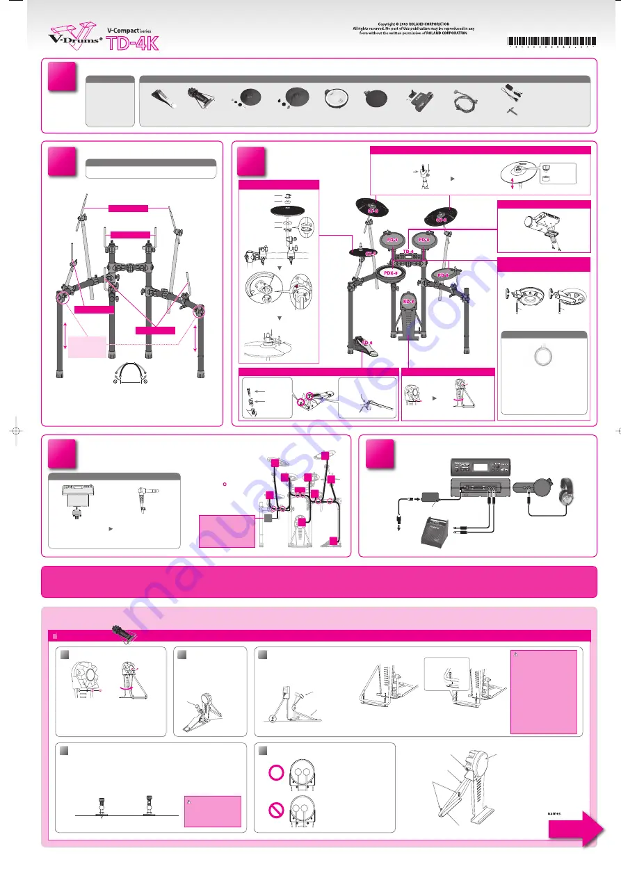
Assembly procedure
Connection procedure
Align with indentation
Tighten the bolt with
a drum key.
Rotation stopper
(note orientation)
Check the included items
Setup Guide
Setup Guide
Hi-hat control
pedal (FD-8)
□
Kick trigger pad
(KD-8)
□
Cymbal pad for
hi-hat (CY-5)
□
Cymbal pad for
crash/ride
(CY-8 x 2)
□
V-Pad for snare
(PDX-8)
□
Pad for tom
(PD-8 x 3)
□
Drum sound
module (TD-4)
□
Connection cable
(special for TD-4)
□
AC adaptor
□
Drum key
(Included in the FD-8 packing carton.)
□
Assemble the stand
Attach the parts
Cymbal mounts
Pad mounts
Pad mounts
If the stand wobbles,
loosen this hand
knob and adjust the
height.
Hi-hat mount
As soon as you open the package, check to see that all items are included. If anything is missing, please contact your dealer.
1.0 m (40”)
Connect the pads to the sound module
Connect the cable to
the TD-4 as shown in
the illustration.
1.
Labels indicating the
pad to be connected are
attached to the cable.
Make connections as
shown in the illustration.
2.
Connect the AC adaptor and speakers
Wing nut
Felt washer
Attach the snare (PDX-8) and
toms (PD-8)
Attach the hi-hat (CY-5)
Attach the crash cymbal (CY-8) and ride cymbal (CY-8)
Assemble the kick (KD-8)
Upper clutch
Clutch felt (large)
Lower clutch
Clutch felt (small)
While pressing
Use Drum Key
to tighten
Attach the sound module (TD-4)
Assemble the hi-hat control pedal (FD-8)
Anchor bolt
Shallower
Deeper
Slide the arm
Adjusting the pedal depth
Attach the anchor bolt
(if installing on a drum mat)
Anchor bolt
Spring for
the anchor bolt
Loosen with the drum key,
and tighten after adjusting
1
3
4
2
5
6
Use cable ties to fasten
the cables at the circled
locations “
” so that they
do not interfere with your
performance.
Make sure to wrap the cable
ties around the pipes.
*
Assemble the stand using the procedure described in the MDS-4 Owner’s
Manual.
Do not spread the stand wider than 1.0 meters (40 inches).
*
Attach the bolt so that
it is at the right when
seen by the performer.
Tighten the wing
nut to obtain an
appropriate amount
of sway.
Finger-tighten all six of the tuning bolts in
the sequence shown in the illustration.
The appropriate amount of tension is one
that will provide approximately the same
striking response as on an acoustic drum.
Use the drum key to adjust the tension as
needed.
1.
2.
3.
Remove the screws
Pull out the stand in the direction of
the arrow, and use the screws you
removed earlier to fasten the stand.
KD-8 (Kick)
03
05
When using on the drum mat
When using on
hard-surfaced flooring
Adjusting the anchor bolts
When using the kick pedal on a drum mat or similar surface, adjust the anchor bolts so their tips pro-
trude from the plate. Then, secure the pedal in place; this will make it easier to use the kick pedal.
However, when used on hard-surfaced fl ooring, the anchor bolts may damage the fl oor. Adjust the
anchor bolts correctly.
When using a twin pedal
Position the two beaters equally apart
from the center of the pad as shown in
the fi gure at left. If one of the beater is
further away from the center than the
other, the sound from the further beater
will be lower in volume, or will not
sound as desired.
Using a twin pedal will result in lower
sensitivity as compared to when a
single pedal is used. Raise the sensitivity
on the sound module.
NOTE
The tips of the anchor bolts
are sharp. Handle with care.
*
Head
Anchor bolt
Stand
Output jack
Foot plate
Detailed explanation of each part
KD-8 component
Use a commercially available kick pedal.
*
Other side
This completes assembly and connections.
Rod
Tighten
Loosen
Rod
Tighten
Loosen
To prevent the inadvertent disruption of power to your unit (should the plug be
pulled out accidentally), and to avoid applying undue stress to the AC adaptor jack,
use cable ties to fasten the cord from the AC adaptor to the stand.
*
Setup Guide (this document)
Owner’s Manual
□
□
Manual set
Before using this unit, carefully read the sections entitled: “USING THE UNIT SAFELY” and “IMPORTANT NOTES.” These sec-
tions provide important information concerning the proper operation of the unit. Additionally, in order to feel assured that
you have gained a good grasp of every feature provided by your new unit, Owner’s manual should be read in its entirety.
The manual should be saved and kept on hand as a convenient reference.
01
03
02
Beater
Install the kick
pedal securely.
Commercially available kick pedal
Beater
* Adjust the height so that the entire pedal
comes into contact with the floor.
This hight will vary depending
on your kick pedal.
Position the beater so that it
strikes the center of the head,
then secure the kick pedal and
KD-8 fi rmly in place.
Depending on your kick pedal, it can be unstable
when you attach it to the KD-8. Be sure to adjust
the foot plate height so that the entire bottom
surface of the pedal is attached to the fl oor.
*
Install the kick pedal securely.
Take care not to pinch your fi ngers.
The tips of the anchor bolts are
sharp. Handle with care.
When moving the KD-8, be sure
to remove the screws and fold the
stand. Transporting the KD-8 while
it remains open may subject the
stand to excessive strain and result
in damage to the stand.
Anti-skid tape is affi
xed to the foot
plate. When transporting the KD-8,
don’t forget to pick up the foot
plate.
*
*
*
*
*
Loosen the stand’s anchor bolts and re-
move the foot plate.
Set the kick pedal so that the entire bot-
tom surface is attached to the fl oor.
1.
2.
In most cases, the stand becomes some-
what elevated. Tighten the anchor bolts
securely there to fi x the stand and foot
plate.
3.
Remove the screws attached to the reverse side of
the KD-8’s trigger.
Pull out the stand in the direction indicated by the
arrow until it is fully extended.
Using any commercially available drum key, tighten
the screws removed in Step 1 so that the stand is
fi rmly secured.
1.
2.
3.
NOTE
Adjusting the foot plate height
Attach the kick pedal
Making the settings
When you’ve fi nished making connections, turn on the power as described in the TD-4 Owner’s
Manual, and verify that you can hear sound.
■
The parts required for mounting the cymbals and the
hi-hat are included in the TD-9K attachment box.
*
HHC
KIK
T1
T2
RD
CR2
CR1
HH
SNR
T3
TD-4
Do not connect the CR2
cable. Leave the cap in place,
and fasten the cable so
that it will not hinder your
performance.
*
All manuals and user guides at all-guides.com
all-guides.com


