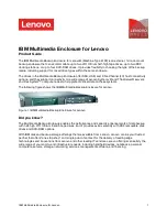
ME-14
Compact Single Board Self-Powered Enclosure
Installation Manual
1.
Introduction
The ME-14 is a simple plastic enclosure suited for a singular PCB and
Rosslare’s BT-16 backup battery. The ME-14 boasts two tamper triggers,
one for the back case detecting wall detachment and one for the casing
itself detecting attempts to open the encasement.
The enclosure is suitable for any one of Rosslare’s ExpansE units, EXP-
1032 Network Controller known as an MU, and the various EUs: EXP-
2024 Dual Reader Door Unit, EXP-2016 16-Relay Elevator Control Unit,
EXP-2088 – 8-Input/Output Interface, as well as Rosslare’s MD-W11
Wireless Access Control Door Interface.
Figure 1: ME-14
2.
Technical Specifications
2.1
Electrical Characteristics
Power
From External source
Backup battery
BT-16
The backup battery has no external power source and has no
charger available, once the backup battery is depleted it needs
to be replaced.
2.2
Environmental Characteristics
Operating Environment
Indoor use
Operating Temperature Range
-10°C to 50°C (14°F to 122°F)
Operating Humidity Range
0 to 95% (non-condensing)
2.3
Physical Characteristics
Dimensions (H x W x D)
130 x 180 x 40 mm (5.1 x 7.1 x 1.6 in.)
Weight
200 g (7 oz.)
3.
Installation
3.1
General
The ME-14 is designed for easy installation. Only a few steps are required
to wire the chosen PCB, install it in the case and mount it onto the wall.
To install the ME-14:
1.
Unscrew the three Philips-head screw located on the bottom of the
unit and push the safety latches to “unlock”.
2.
Open the case upwards in accordance with the notches located on
the top of the case.
3.
Use the designated notches to install the PCB and backup battery
into the ME-14 case.
4.
Wire the unit being installed according to the wiring instructions as
explained in the relevant installer manual.
5.
Mount the PCB into the designated area; align the PCB holes with
those of the encasement.
6.
Mount the backup battery (optional) onto the designated location on
the top right side of the encasement.
Figure 2: ME-14 Assembly
3.2
Mounting the ME-14
Select an area for mounting the ME-14, and ensure the location is flat,
for perfect mounting of the unit. When using the ME-14 with the MD-
W11, make sure to mount the ME-14 in a location suited for wireless
reception.
To mount the ME-14:
1.
Using the holes dimensions and locations shown in Figure 2, drill
holes in the wall. Alternatively, use the ME-14’s back plate as a
template.
2.
Insert masonry anchors into the drilled holes.
3.
Mount the PCB into the designated area; align the PCB holes with
those of the encasement.


