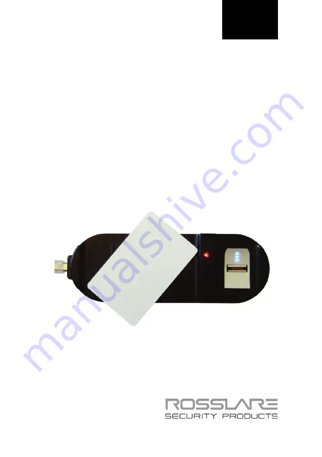
background image


2012 
March 

CP-R25 & AS-B01 

Mifare

®

 Card Programmer/Fingerprint 

Swipe Enrollment Station and Software 

Hardware and Software Manual

Summary of Contents for Mifare AS-B01

Page 1: ...2012 March CP R25 AS B01 Mifare Card Programmer Fingerprint Swipe Enrollment Station and Software Hardware and Software Manual ...

Page 2: ...erty rights covering the subject matter in this manual TEXTS IMAGES AND ILLUSTRATIONS INCLUDING THEIR ARRANGEMENT IN THIS DOCUMENT ARE SUBJECT TO THE PROTECTION OF COPYRIGHT LAWS AND OTHER LEGAL RIGHTS WORLDWIDE THEIR USE REPRODUCTION AND TRANSMITTAL TO THIRD PARTIES WITHOUT EXPRESS WRITTEN PERMISSION MAY RESULT IN LEGAL PROCEEDINGS The furnishing of this manual to any party does not give that par...

Page 3: ...ments 11 3 Installation 12 3 1 Unpacking the Equipment 12 3 2 CP R25 Description 12 3 3 AS B01 Software Installation 12 3 4 Connecting the CP R25 15 4 AS B01 Software Overview and LEDs 18 4 1 Software Overview 18 4 2 Indication LEDs 19 5 Programming Cards and Tags 21 5 1 Programming a Master Card 23 5 2 Programming a Configuration Card 23 5 2 1 Sector Reader Configuration Cards 24 5 2 2 Fingerprin...

Page 4: ...3 6 1 6 Erasing Specific User Card Data 34 6 1 7 Read Serial Number and Card Type 35 6 1 8 Changing KeyA and Erasing All Data 35 6 2 Fingerprint Utilities 36 6 2 1 Enrolling Fingerprints on a Pre configured User Card 36 6 2 2 Verifying Fingerprint Enrollment on a User Card 37 7 Global Options 39 7 1 Change Password 39 7 2 Card Overwrite 39 7 3 Updating Firmware 40 A Maintenance 42 B Field Descript...

Page 5: ...reas 22 Figure 12 Read Configuration Card 30 Figure 13 Read ID from User Card 31 Figure 14 Program ID into User Card 32 Figure 15 Change User Card KeyA on Selected Sector 32 Figure 16 Change User Card KeyA on All Sectors 33 Figure 17 Erase User Card Selected Block 34 Figure 18 Read Serial Number and Card Type 35 Figure 19 Change User Card KeyA and Erase Data All Sectors 36 Figure 20 Enroll Fingerp...

Page 6: ...List of Tables vi CP R25 Hardware and AS B01 Software Manual List of Tables Table 1 Indication LEDs 19 Table 2 Field Descriptions 43 ...

Page 7: ...nfiguration of the system with the maximum number of functions including future options Therefore not all functions described in this manual may be available in the specific system and or product configuration you purchased Incorrect operation or installation or failure of the user to effectively maintain the system relieves the manufacturer and seller from all or any responsibility for consequent...

Page 8: ...sslare s powerful AS B01 Programmer software package 1 2 Desktop Convenience The CP R25 is small and lightweight with a slim and attractive design It is built for convenience and portability with a USB 2 0 computer interface which makes it quick to install and allows it to run without any additional power source Figure 1 The CP R25 Designed to sit safely on any desktop the CP R25 is sturdily built...

Page 9: ...The CP R25 Desktop Programmer is a feature rich Mifare card programmer and fingerprint enroller 1 6 CP R25 Desktop Programmer Enables the user to read verify and program Mifare proximity cards Uses a swipe type fingerprint sensor Supports USB 2 0 computer connections Utilizes LED and buzzer sub systems to indicate programming card and power supply status Runs a thorough internal diagnostic self te...

Page 10: ... the sensor surface FAR False Accept Rate Actual values depend on specific user s finger usage condition and quality of enrollment Specification 0 0010 1 100000 FRR False Reject Rate Actual values depend on specific user s finger usage condition and quality of enrollment Specification 2 1 50 Electrical Specifications Operating Voltage 5 VDC Via USB Input Current 75 mA standby 160 mA maximum CP R25...

Page 11: ...AS B01 Software Manual 11 2 2 AS B01 Software Requirements Minimum Software Requirements Operating System Windows XP SP2 Framework Microsoft NET 2 Processor 400 MHz Pentium or equivalent RAM Memory 512 Mbytes Free HD space 1 Gigabyte Connection Port USB ...

Page 12: ... items listed below are received before beginning If any items are missing contact your dealer immediately One CP R25 Programmer One Male A to Male B USB Cable One Software CD Instruction Manual 3 2 CP R25 Description The following figure illustrates the CP R25 components Figure 2 CP R25 Components 3 3 AS B01 Software Installation The AS B01 software is included on the installation CD ROM which is...

Page 13: ...lick on the CD drive icon and then double click the AS B01 setup file If Microsoft NET 2 Framework is not installed on the computer it is installed automatically before beginning the AS B01 installation The installation package extracts the installation files After the files are extracted the Welcome to the CP R25 Setup Wizard screen opens Figure 3 AS B01 Setup Welcome Screen 3 Click Next The Sele...

Page 14: ... 5 ASB01 Setup Disk Space Availability 5 Select the users allowed to use the program Everyone or Just me For security purposes it is suggested that Just me is selected 6 Optional You can change the destination folder of the installation a Click Browse The standard Windows Explorer window opens b Navigate to and select the required folder 7 Click Next to continue the installation process The Confir...

Page 15: ... the unit for enrollment Before connecting the CP R25 hardware ensure that the ASB01 software is installed and running To connect the CP R25 1 Click the AS B01 icon on the desktop or select the program from the Rosslare folder in the Start menu The login dialog opens Figure 6 AS B01 Login Dialog 2 Enter a password When using the application for the first time use the default password of admin Afte...

Page 16: ... the other end connects to the USB connector on the Desktop Programmer Windows automatically installs the required drivers The Desktop Programmer receives its power through the USB no external power supply is required On the AS B01 main window the connection indicator at the bottom of the window changes from red to green with the description Connected to indicate that the CP R25 Desktop Programmer...

Page 17: ...reen and the description still indicates Disconnected after the USB cable is connected try disconnecting the USB cable from the Desktop Programmer and reconnecting it When the hardware and software are disconnected the software can only function in demonstration mode Once the indicator is green and the description is Connected the CP R25 Desktop Programmer is ready for use ...

Page 18: ...rect password the main software window opens Figure 9 AS B01 Main Window Layout The AS B01 main window consists of the following functional areas File menu area Used for general operations such as setting global options on the Desktop Programmer getting version information and closing the software Configuration Tab area The main working area which is used for entering and displaying all card and s...

Page 19: ...on success or failure messages or instruction messages such as during fingerprint enrollment Status information area Indicates connection status with the CP R25 Desktop Programmer hardware 4 2 Indication LEDs The following table describes LED behavior on the CP R25 Programmer see Figure 2 Table 1 Indication LEDs Event Swipe Card Reader LED Fingerprint Reader LED Buzzer Fingerprint Directional Indi...

Page 20: ... in circular mode to indicate finger swipe Read fingerprint success Off Green on for 3 sec 3 high tone beeps Rolling LEDs in circular mode to indicate finger swipe Read fingerprint fail Off Red on for 3 sec Long buzz Turning all LEDs on and then according to status leaving all on or going back to circular mode Read finger timeout When no finger is passed over the scanner for 30 seconds the CP R25 ...

Page 21: ... area is the same for all configuration functions Operations area This area varies according to the configuration function being performed The configuration function is selected in the Operation Type dropdown menu The following 2 sub areas appear depending on what options are selected in Operation Mode and Operation Type Reader Specific Configurations area This area is visible when the Sector Read...

Page 22: ...0 AS B01 Sector Reader Configuration Tab Areas When programming a Mifare card or tag the card or tag is placed on the CP R25 Desktop Programmer antenna area The following figure illustrates where these areas are located on the CP R25 Desktop Programmer Figure 11 CP R25 Antenna Areas ...

Page 23: ...nt for configuring Master card The default value of Sector can be used 3 In Card Type select either Mifare 1 K or Mifare 4 K 4 From the Transmit Format dropdown menu select the applicable transmission format 5 Place either a blank Mifare card or a Mifare card that has been previously used as a Master card on the CP R25 Desktop Programmer antenna area 6 Click Start to begin programming the Mifare c...

Page 24: ... 7 Ensure that Operations is set to Program Card 8 Define the Led and Buzzer Control behavior by selecting or clearing the Enable Led and Enable Buzzer checkboxes 9 For readers with a keypad a Select the Keypad checkbox Additional keypad options appear b In the Backlight options dropdown menu select the backlight behavior c From the Transmit Format dropdown menu set the keypads transmission format...

Page 25: ...d 8 Define the Led and Buzzer Control behavior by selecting or clearing the Enable Led and Enable Buzzer checkboxes 9 To enable the Lockout feature a Select the Enable checkbox b Define the lockout behavior using the Attempts and Duration fields 10 For reports on operational failures select the Enable checkbox under Failed operation reporting 11 In KeyA enter the KeyA to be used by the reader as t...

Page 26: ...usly configured Mifare User Card configuring the Card ID and card key at the same time For a previously configured Mifare User Card configuring the Card ID card key and fingerprint enrollment at the same time Once a card is configured the Card ID and the KeyA value can be modified or if required completely wiped from the card 5 3 1 Programming a Sector Reader User Card The first stage of preparing...

Page 27: ...enna area 11 Click Start to begin programming the Mifare card On completion a message appears in the Message Log area to verify that the programming succeeded If the programming fails there is a short buzz and the swipe Card Reader LEDs lights red for three seconds 12 To program additional Mifare User Cards repeat Step 8 and then Steps 10 and 11 5 3 2 Programming and Enrolling Fingerprint User Car...

Page 28: ... KeyA remains active until it is changed after configuring the reader 10 In Fingers options select the number of fingers per card to enroll onto the Mifare User Card 11 Optional Select the Verify after enrollment checkbox to verify the enrolled fingerprints if required This is usually not required as the CP R25 Desktop Programmer has an automatic internal verification during enrollment 12 If neede...

Page 29: ...card programming 3 short beeps are generated and a success message Writing template to card succeeded appears in the Message Log area If the programming fails there is a short buzz and the swipe Card Reader LEDs light red for three seconds 17 To program and enroll additional user cards repeat Step 8 and then Steps 13 to 16 ...

Page 30: ...ns available When Sector is selected the same two card utilities are available plus six additional utilities specific to the Sector type card 6 1 1 Reading a Configuration Card This function is used to confirm the card configuration when performing other functions in order to save time and enhance accuracy To read the Configuration cards 1 Select either the Sector Reader or CP R25 tab 2 Select the...

Page 31: ...from User Card The KeyA and User Card ID fields appear 7 Enter the KeyA of the card being read 8 Place the Mifare User Card on the CP R25 Desktop Programmer antenna area 9 Click Start to display the card ID in the Mifare User Card ID field 6 1 3 Programming a User Card ID This utility is used to program the User Card ID into a specific location on the User card without configuring the card templat...

Page 32: ... programming procedure 6 1 4 Changing the User Card KeyA in a Specific Sector Use this utility to change the KeyA value in a specific sector of the User Card without changing the card template or User Card ID This option is only available for the Sector Operation Mode To change the KeyA in a specific sector 1 Select either the Sector Reader or CP R25 tab 2 Select the Sector Operation Mode 3 Select...

Page 33: ...red the original site installation The current KeyA remains active until it is changed after configuring the reader 8 Place the Mifare User Card on the CP R25 Desktop Programmer antenna area 9 Click Start to program the card with the new KeyA 6 1 5 Changing the User Card KeyA in All Sectors Use this utility to change the KeyA value in all sectors of the User Card without changing the card template...

Page 34: ...e until it is changed after configuring the reader 7 Place the Mifare User Card on the CP R25 Desktop Programmer antenna area 8 Click Start to program the card with the new KeyA 6 1 6 Erasing Specific User Card Data This utility is used to erase specific information from a defined sector within the card This option is only available for the Sector Operation Mode To erase specific user card data 1 ...

Page 35: ...er and card type Figure 18 Read Serial Number and Card Type The Serial Number field appears 5 Place the Mifare User Card on the CP R25 Desktop Programmer antenna area 6 Click Start to display the serial number and card type 6 1 8 Changing KeyA and Erasing All Data Use this utility to format a card to define a new KeyA which is written on all sectors This option is only available for the Sector Ope...

Page 36: ...eyA entered the original site installation The current KeyA remains active until it is changed after configuring the reader 7 Place the Mifare User Card on the CP R25 Desktop Programmer antenna area 8 Click Start to start the formatting procedure This operation may take up to 30 seconds for a 1K card and several minutes for a 4K card Do not close the application or remove the card until you receiv...

Page 37: ...on the CP R25 Desktop Programmer in the direction indicated by the Fingerprint Directional Indication LEDs 11 Follow the instructions messages in the Message Log area to repeat the fingerprint swipe process three 3 times To write the finger template onto a specific card sector define the sector number by typing or selecting the number in the Sector Number field located in the finger options sectio...

Page 38: ...nt template location 7 Place the card on the CP R25 Desktop Programmer antenna area 8 Click Start to begin programming the Mifare card 9 Instruct the person whose fingerprints are being verified to swipe his her finger on the finger sensor located on the CP R25 Desktop Programmer in the direction indicated by the Fingerprint Directional Indication LEDs 10 Follow the instructions messages in the Me...

Page 39: ...ge Password window opens Figure 22 AS B01 Change Password 2 Complete the fields as required Passwords are case sensitive For higher security make sure that the password you choose is more than 4 letters long Mixing letters and numbers also substantially strengthens the password All passwords are hidden by characters to avoid exposing it to an unauthorized user 3 Click OK The password is changed 7 ...

Page 40: ... 1 In the File menu click Options Firmware Programming The Desktop Reader Firmware Programming window opens Figure 24 AS B01 Desktop Reader Firmware Programming 2 Optional You can change the default firmware location that is displayed in the bin file location field a Click Browse The standard Windows Explorer window opens b Navigate to the folder containing the binary firmware file to download c S...

Page 41: ... the USB Cable 7 Wait until the indicator at the left bottom side of the screen displays Connected The installation automatically begins On completion a confirmation screen opens 8 Click OK The Desktop firmware is now updated Two more messages should immediately follow in the Message window Mifare Programming Reader Disconnected and Mifare Programming Reader Connected The Desktop Programmer is now...

Page 42: ...following these guidelines as closely as possible Do not expose the unit to water or rain or to humidity over the specified safety level Do not expose the unit to direct sunlight for extended periods This can cause overheating and system failure Avoid dropping the unit onto the ground This may cause electromechanical failure ...

Page 43: ...blocks and 8 sectors with 16 blocks Each block contains 16 bytes In the erased state the EEPROM cells are read as a logical 0 in the written state as a logical 1 Confirm Password Used to confirm a new password entered in the New Password field Current Password Password used to enter the AS B01 software application and when changing the password Enable Buzzer Activates or deactivates the reader s b...

Page 44: ...bstantially strengthens the password Reader KeyA The Mifare card storage is divided into sectors with each sector being protected by two different keys KeyA and KeyB These keys are programmable according to company security specifications KeyB is not supported Sector In the Operation Mode area this option is selected if the reader has to transmit encrypted data from the card secured memory More sc...

Page 45: ...d is read from manufacture block C 2 Data Blocks All sectors contain 3 blocks of 16 bytes for storing data Sector 0 contains only two data blocks and the read only manufacturer block The data blocks can be configured by the access bits as Read write blocks for example contactless access control Value blocks for example electronic purse applications not supported by AS B01 An authentication command...

Page 46: ...onal Mifare Card Memory Map Information 46 CP R25 Hardware and AS B01 Software Manual Figure 27 Mifare 1K Memory Diagram For further details about Mifare cards refer to the NXP Semiconductor Mifare datasheet ...

Page 47: ... following sample form can be used Employee Security Card Configuration Field Configuration Employee Name Employee ID Employee Company ID Employee Dept Card Serial Number if applicable Reader KeyA Transmit Format Card Type 1K or 4K ID Location Sector Number ID Location Block Number ID Location Byte Number Mifare User Card ID Number of Fingerprints 1 or 2 LED Control Buzzer Control Lockout Attempts...

Page 48: ...e with the terms of this warranty Unless otherwise requested by a ROSSLARE representative return of the failed product s is not immediately required If ROSSLARE has not contacted the Customer within a sixty 60 day holding period following the delivery of the warranty claim Customer will not be required to return the failed product s All returned Product s as may be requested at ROSSLARE S sole dis...

Page 49: ... of or tampering with the Product if Product disassembled or repaired in such a manner as to adversely affect performance or prevent adequate inspection and testing to verify any warranty claim ROSSLARE does not warrant the installation maintenance or service of the Product Service life of the product is dependent upon the care it receives and the conditions under which it has to operate In no eve...

Page 50: ...ree 1 866 632 1101 Local 1 817 305 0006 Fax 1 817 305 0069 support na rosslaresecurity com Europe Rosslare Israel Ltd Rosh HaAyin Israel Tel 972 3 938 6838 Fax 972 3 938 6830 support eu rosslaresecurity com Latin America Rosslare Latin America Buenos Aires Argentina support la rosslaresecurity com China Rosslare Electronics Shenzhen Ltd Shenzhen China Tel 86 755 8610 6842 Fax 86 755 8610 6101 supp...

Reviews: