background image

OPERATION AND MAINTENANCE MANUAL

8029 S 200th St. Kent, WA 98032 USA  |  www.rottlermfg.com  |  Ph: 253-872-7050  |  Fax: 253-395-0230

16.03.2017

Summary of Contents for S7M

Page 1: ...OPERATION AND MAINTENANCE MANUAL 8029 S 200th St Kent WA 98032 USA www rottlermfg com Ph 253 872 7050 Fax 253 395 0230 16 03 2017 ...

Page 2: ......

Page 3: ... model and serial number 6 Part number and description of what you want to order 7 Preferred method of shipment 8 You may also contact us via e mail with the above information Send e mail requests to parts rottlermfg com In some cases you may be requested to send a photo of the part you are ordering if it is a replacement part or doesn t appear in the database If you are unsure which part you need...

Page 4: ......

Page 5: ...he CONTROL DEFINITIONS to get an idea how the machine operates The Operating Instructions chapter should be read in order to familiarize the user with the actual button pushing sequences required to carry out a job These chapters in the manual should be considered an introduction As the operators of the S7M S8M series machines gain experience with using the different functions of the machine compl...

Page 6: ...cluding without limitation sale resale license rental or lease without the prior express written consent of Rottler Manufacturing Rottler Manufacturing does not make any representations warranties or guarantees express or implied as to the accuracy or completeness of the Manual Users must be aware that updates and amendments will be made from time to time to the Manual It is the user s responsibil...

Page 7: ...handise authorized for return must be returned prepaid If merchandise is returned with shipping charges collect the actual amount of these charges may be deducted from any credit which may be due the customer The RGR assigned by the Order Department should be written on the shipping label and must appear on a copy of the invoice s covering the original shipment This invoice copy must be included i...

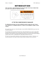
Page 8: ...Section 1 Introduction S7M S8M Manual www rottlermfg com 1 4 ...

Page 9: ...anual www rottlermfg com I INSTALLATION Contents ROTTLER S7 8 SERIES INSTALLATION REPORT 2 2 Installation Procedure 2 6 Location 2 6 Unpacking 2 6 Shipping Hold Down Bolt 2 6 Leveling 2 6 Air Supply 2 6 Power Supply 2 7 Grounding 2 7 ...

Page 10: ...ew Rottler machine please be sure to sign the installation report after the installation technician has installed the machine and verified the machine is operating correctly and given the operators operation and maintenance training Thank you for your cooperation and the opportunity to be of service to you ROTTLER MANUFACTURING ...

Page 11: ... likely to interfere with machine operation unexpectedly Customer is responsible for providing electricity to machine in a manner that meets the local electrical code requirements ______Check machine with precision level and for equal support on feet then carefully adjust supports to precisely secure the best average flatness of the top table ______This machine requires 208 to 240V AC 1 phase 50 6...

Page 12: ...s the slack in the actuator nut with air cylinder control Caution operator of result if a surfacing setting is ever made in the relief up position ______Exercise spindle rotation speed controls fast travel feeds and stop adjustments ______Have operator perform machine functions and automatic cycles on applicable machines ______Remove back of cutter head guard and have operator unclamp rotate and c...

Page 13: ...cks such as 3208 Cats and adaptations to odd angles such as the Ford super duty truck block ______Explain procedures to surface protruding cylinder sleeves flush with the block surface IN LINE BLOCK RESURFACING ______Assemble in line tooling demonstrating support levels to accommodate a great variety of blocks ______In addition to adequate hold down force explain the use of chocking or providing s...

Page 14: ...______________________________________________ ____________________________________________________________________________________ ____________________________________________________________________________________ ____________________________________________________________________________________ ____________________________________________________________________________________ _____________...

Page 15: ...ate from the S7M S8M machine do not use force on any part of the spindle unit Remove the tool box parallels and optional tooling located at the lower portion of the machine and completely clean these articles as well as the machine base pads and upper table with solvent Rust inhibitor is applied to the machine at the time of shipment any of this inhibitor left on the machine will result in conside...

Page 16: ...e damaged Do not attempt to attach three phase voltage to this machine The three phase spindle motor receives it s power from a three phase variable frequency drive in the rear enclosure The frequency inverter is powered by single phase Connect single phase wiring to the blue and gray connection terminals in the upper right hand side of the rear enclosure The machine is not neutral hot leg sensiti...

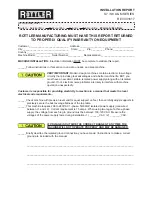
Page 17: ...Section 2 Installation S7M S8M Manual www rottlermfg com 2 8 ...

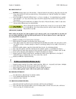
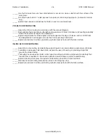
Page 18: ...Section 2 Installation S7M S8M Manual www rottlermfg com 2 9 ...

Page 19: ...Section 3 Safety S7M S8M Manual www rottlermfg com I SAFETY Contents Safety Information 3 1 Safety Instructions for Machine Use 3 1 Electrical Power 3 3 Machine Operator 3 4 Emergency Procedure 3 5 ...

Page 20: ...n which if not avoided may result in minor or moderate injury CAUTION used without the safety alert symbol indicates a potentially hazardous situation which if not avoided may result in property damage Safety Instructions for Machine Use This machine is capable of causing severe bodily injury ONLY A QUALIFIED EXPERIENCED OPERATOR SHOULD OPERATE THIS MACHINE NEVER ALLOW UNSUPERVISED OR UNTRAINED PE...

Page 21: ... other conditions that may affect its operation A guard or other part that is damaged should be properly repaired or replaced NEVER OPERATE A MACHINE WHEN TIRED OR UNDER THE INFLUENCE OF DRUGS OR ALCOHOL Full mental alertness is required at all times when running a machine IF AT ANY TIME YOU ARE EXPERIENCING DIFFICULTIES performing the intended operation stop using the machine Then contact our ser...

Page 22: ...n serious personal injury damage to equipment or poor work results Electrical Power All electrical power should be removed from the machine before opening the rear electrical enclosure In the event of an electrical short grounding reduces the risk of electric shock by providing a path of least resistance to disperse electric current Electrocution or a fire can result if the machine is not grounded...

Page 23: ... other electrical equipment grinders welders and other AC motors electrical noise can be induced into this machines electrical system Electrical noise can cause the controller to see false signals to move Not supplying a fully isolated supply to the machine may void factory warranty Refer to the Power supply section located in the Installation section for voltage and amperage requirements of this ...

Page 24: ...ires a complete power disconnection from the machine Emergency Procedure Assuming one of the following has occurred tool bit set completely off size work piece or spindle base not clamped spindle is not properly centered and these mistakes will become obvious the minute the cut starts PRESS THE EMERGENCY STOP BUTTON on the front control panel IMMEDIATELY Find out what the problem is return the spi...

Page 25: ...ITIONS Contents Control Definitions 4 1 CPU Control 4 1 Master Power On Off Switch 4 1 Button Definition 4 1 Emergency Stop 4 2 Homing 4 2 Right 4 2 Left 4 2 Spindle Start 4 2 End of Cut Set Button 4 2 Feed Rate 4 2 Spindle RPM 4 2 Cycle Start 4 3 Surface Depth Dial Indicator 4 3 ...

Page 26: ...his manual these functions will become clear CPU Control This machine is under control of a CPU located in the rear enclosure Master Power On Off Switch This switch is located on the upper right hand side of the rear electrical cabinet This switch must be in the Off position to open the rear enclosure When first applying power to the machine it will take a short while for the system to be ready fo...

Page 27: ...ed again or the right end of travel is reached Left This button has two functions When pressed and held the machine will travel to the left at 80 per minute until the button is released or the Left end of travel is reached If the spindle is on when this button is pressed the machine will Feed to the left at the rate shown Travel will continue until the button is pressed again or the left end of tr...

Page 28: ...ied on the dial Once the spindle is up to speed the horizontal feed will start at the rate specified on the knob When the end of cut position is reached the horizontal feed will stop and index cutter head The Right Button LED will blink Press Right Button to return home To set end of cut move machine over to end of work piece enough to allow cutter to clear work piece Press Set End Of Cut button S...

Page 29: ...eral Insert Information 5 4 Cutting Speed Calculation 5 4 Surfacing Inserts 5 5 6303B 5 5 6303M 5 5 6303U 5 5 6303K 5 5 RS322 5 5 6301J 5 5 1 2 12 70mm Surfacing Inserts 5 6 6303P 5 6 6303Q 5 6 Bi metal Surfacing 5 6 Cylinder Heads with Protruding Valve Seats 5 7 6303S 5 7 6303U 5 7 6303R 5 7 6301I 5 7 6301V 5 7 Special Toolholder and Insert 5 8 7202X 5 8 7202Z 5 8 ...

Page 30: ...ock or other type of job For details of operating specific fixtures available on this machine refer to the Optional Surfacing Fixtures and Tooling section of this manual There are several ways to use the SM machine cutting system depending on the type of work you do and your personal preferences Following are some details and descriptions that will help you decide which method is best suited to yo...

Page 31: ...adjusted see the Maintenance chapter of this manual for adjustment instructions it will indicate the depth of the cut at your current height setting Adjust the depth of the cut using the manual handwheel Adjust the Feed Rate and Spindle RPM knob for the desired finish Press the Spindle Start button and the Feed Left button The machine will start Feeding across the work piece When the machine has f...

Page 32: ...ton the spindle will come up to speed then press the Left Feed button and the left feed will start When the cutterhead clears the work piece press the SET button twice This will set the end of cut for the next pass If a cycle is started with an end of cut position already set the machine will stop the spindle and left feed at this position The cutterhead will index so the cutter is not over the wo...

Page 33: ...tler S F60 F70 and F100 Series surfacing cutterheads are supplied standard with Rottler 3 8 IC toolholders fitted to our surfacing heads Optional 1 2 toolholders are interchangeable with 3 8 toolholders Insert breaking or chipping can be caused by several things It can be caused by not operating the insert at the correct RPM It is very typical for an insert to break or chip when cutting too slow I...

Page 34: ...heads and blocks often found in the performance industry RPM speeds with a 14 cutter range from 650 750 RPM 6303K A round 3 8 IC single sided coated carbide insert This is a very economical general purpose insert for surfacing aluminum It is advisable to use this insert for rough cutting to remove welding or contaminants before A PCD insert should be used for the final cut to give the super fine f...

Page 35: ...s and Aluminum Blocks with Hard Sleeves Cylinder heads with pre combustion chambers or aluminum engine blocks with cast iron or steel cylinder sleeves are a challenge to cut and most often require a special cutting insert and special cutting technique There are many different material combinations so there is not one insert that works the best on all applications Below is information to use as a g...

Page 36: ...surfacing Spray RPM speeds with a 14 cutter range from 650 750 RPM 6303U A round 3 8 IC single sided CBN Insert This insert does an excellent job when cutting hard cast iron blocks and heads of a single material or bi metal This insert is the best to use when machining compacted graphite cast iron heads and blocks often found in the performance industry RPM speeds with a 14 cutter range from 650 7...

Page 37: ...luminum cylinder heads with pre combustion chamber and cast iron heads with soft pre combustion chambers like Land Rover Use in 7202X tool holder only RPM speeds with 14 cutter range from 450 550 RPM and with a 16 cutter 400 500 RPM One Insert Two Inserts Set within 0015 0003 Two Inserts Set within 0001 RPM 1000 Feed Rate 002 Per Rev 12 rms 12 rms 10 rms RPM 1000 Feed Rate 005 Per Rev 20 rms 20 rm...

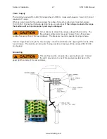
Page 38: ...Section 5 Operating Instructions S7M S8M Manual www rottlermfg com 5 9 ...

Page 39: ...on Illustration 6 3 Setting Cutting Tool Inserts 6 4 Production Cutting 6 4 Aluminum Cast Iron 6 4 Dial Indicator Setting 6 5 Vertical Travel Belt 6 6 Upper Vertical Travel Belt 6 7 Drive Belt Replacement 6 8 Drive Sprocket Motor Removal and Replacement 6 9 Removal of Drive Sprocket 6 9 Replacement of Drive Sprocket 6 9 Driven Sprocket Removal and Replacement 6 10 Removal of Driven Sprocket 6 10 R...

Page 40: ... 19 Inner Spindle Adjustment 6 20 Alignment Definitions for Angular Bearings and Belleville Washers 6 21 Bearing Alignment 6 21 Belleville Washer Alignment 6 21 Z Axis Vertical Ballscrew Lower Bearing Stacking Order 6 22 Z Axis Vertical Ballscrew Lower Bearing Section View 6 22 Inner Spindle Upper Section Belleville Washer Stacking Order 6 23 Inner Spindle Upper Section Belleville Washer Section V...

Page 41: ...ndle is directly connected to the cutterhead Every 40 hours Add 2 or 3 drops of ISO VG 32 Hydraulic Oil Every 175 hours Add one shot of NLGI 2 White Lithium Grease Run the spindle down near the lower limit and you will see a flush type grease fitting in the spindle Add lubrication here If the inner spindle is removed clean the lower bearing and repack it with grease Cleaning The Way Surface Do not...

Page 42: ...Section 6 Maintenance S7M S8M Manual www rottlermfg com 6 2 S7M S8M Machine Lubrication Illustration ...

Page 43: ...Section 6 Maintenance S7M S8M Manual www rottlermfg com 6 3 2 Axis Universal Machine Table 7119Q Lubrication Illustration ...

Page 44: ...ill pop out and hit the back of the slot Tighten the set screw This way when a tool holder is removed and then replaced it will be located very nearly where it was Insert height will still need to be adjusted Rotate cutter head and check to see that both inserts are the same height within 0015 0003 If adjustment is necessary loosen the tool holder clamp wedge then alternately loosen and tighten th...

Page 45: ...handling the cutter head Touch off surface by turning hand wheel clockwise until cutter insert just touches test piece surface when rotated back and forth Note Do not lower the cutter head directly onto surface it may chip the cutting tool insert Make a very light cut on your test piece about one inch in Back out and without adjusting the height press the dial indicator down on this surface Adjust...

Page 46: ...ar of the machine shroud Remove the five screws mounting the shroud to the machine Four screws are located inside the enclosure and are accessed through the rear opening The other screw is in the front on the left side from the outside Lift cover off the machine carefully As cover is lifted slide forward and up to clear motor and belt case Remove six screws from the belt housing cover and lift it ...

Page 47: ...lts Loosen the two upper belt or four lower belt bracket mounting bolts Turn the Belt Tension adjustment bolts CCW until they are our of the mounting brackets Push the idler pulleys and bracket towards the belt Remove belts Follow this procedure in reverse order to install the belts Adjust belts for 12 3 17 mm deflections when 3 to 4 lbs 6 61 to 8 82 kg pressure is applied ...

Page 48: ...ght side from the outside Lift cover off the machine carefully As cover is lifted slide forward and up to clear motor and belt case Remove the four screws holding the upper cover Lift cover off Loosen the four motor mount screws Loosen the belt tension screw Lift the belt off Replace with new belt 7247E Tighten belt tension screw until belt has 1 8 to 3 16 inch deflection with 1 1 2 to 3 pounds pr...

Page 49: ...shing Use three screws in the threaded holes in the bushing to loosen the bushing from the sprocket Lift off sprocket Replacement of Drive Sprocket Clean bushing and sprocket Do not use any lubrication on bushing sprocket or screws Locate sprocket even with driven sprocket on the inner spindle Tighten the 10 24 screws in the bushing EVENLY to 5 to 6 ft lbs Replace the drive belt and adjust as indi...

Page 50: ...on and arraignment of the two Belleville springs below the index bushing Replacement of Driven Sprocket Clean bushing and sprocket Do not use any lubrication on bushing sprocket or screws Assemble the sprocket back onto the index bushing Slide the index bushing and key back onto the inner spindle making sure the Belleville springs are in place Install the adjusting nut back on the inner spindle an...

Page 51: ...chine before continuing Mark cutterhead and spindle so they can be reassembled in the same position Remove cutterhead by removing its four 3 8 16 screws Remove chip guard by removing its two 1 4 20 set screws that go into the clamp ring at an angle and loosen the 3 8 16 cap screw in the split line of clamp ring Remove cover ...

Page 52: ...of the way Remove the screw holding the top of the Linear Scale on to the Upper Housing Remove the four 4 bolts holding the vertical ballscrew nut to the Upper Housing Remove the three 3 bolts located at the top of the Outer Spindle A The Upper Housing will lift off It may require some heat as you lift to get it off If needed apply heat to the area where the housing is bolted to the spindle using ...

Page 53: ...r adjusting nut back onto inner spindle to keep the spindle from falling out after throwback nut is unthreaded Take a rod or punch and insert it into one of the holes in the outside of the throwback nut This nut is located between the bottom of the outer spindle and the lower flange of the inner spindle Turn the nut clockwise to loosen As you back off the nut tap on top of the inner spindle with a...

Page 54: ...id from the Upper Housing Rotate the spindle until the head of the Hex nut is directly in front of the sensor The distance between the sensor and the hex bolt should be 030 If it is not loosen the two nuts on the sensor and back them off until 030 is achieved Turn the spindle by hand to make sure the dowel pin is not coming in contact with the sensor ...

Page 55: ...nt Plate 4 Remove the belt 5 Loosen the four mounting bolts on both of the ballscrew supports one at each end 6 Move the machine to the home position all the way right Tighten the four mounting bolts on the right hand ballscrew support 7 Move the machine to it s full left hand travel Tighten the four mounting bots on the left hand ballscrew support 8 Install the belt onto the ballscrew and motor p...

Page 56: ...ir Adjustment of the S7M S8M Machine The Regulator for the counter balance air cylinder is located in the Spindle Base Remove the rear cover to access the regulator This pressure should be approximately 9 to 15 psi Note Maximum 20 psi Air Adjustments Illustration ...

Page 57: ...Section 6 Maintenance S7M S8M Manual www rottlermfg com 6 17 Pneumatic Control Diagram ...

Page 58: ...leading edge of the cutterhead should be 0025 to 004 inch lower than the right trailing edge of the cutterhead If the tilt is not within this tolerance it will need to be adjusted Loosen the six allen head bolts holding the 7004D bushing to the bottom of the spindle base Snug the bolts up very lightly Use the three set screws located just above the lower bushing near the lower edge of the spindle ...

Page 59: ...lear position making sure the spindle can travel its full vertical length Thoroughly clean and lightly oil the Outer Spindle before adjustment Remove the lower wiper retainer ring along with the wipers and felts to expose the lower spindle bushing adjustment nut Loosen the set screws located on the front of the upper and lower portion of the Spindle Base Loosen the upper and lower bushing adjustme...

Page 60: ... adjustment rod should be 1 4 5 16 inch diameter and 8 to 10 inches long Carefully rotate the cutterhead counter clockwise looking from above the cutterhead letting the adjustment rod move against the end of the slot This tightens the inner spindle adjustment The cutterhead will be easy to turn and you should be able to feel the spring loaded detent in the adjustment nut At some point the torque r...

Page 61: ...Section 6 Maintenance S7M S8M Manual www rottlermfg com 6 21 Alignment Definitions for Angular Bearings and Belleville Washers Bearing Alignment Belleville Washer Alignment ...

Page 62: ...Section 6 Maintenance S7M S8M Manual www rottlermfg com 6 22 Z Axis Vertical Ballscrew Lower Bearing Stacking Order Z Axis Vertical Ballscrew Lower Bearing Section View ...

Page 63: ...Section 6 Maintenance S7M S8M Manual www rottlermfg com 6 23 Inner Spindle Upper Section Belleville Washer Stacking Order Inner Spindle Upper Section Belleville Washer Section View ...

Page 64: ...Section 6 Maintenance S7M S8M Manual www rottlermfg com 6 24 Inner Spindle Lower Section Bearing Stacking Order ...

Page 65: ...Section 6 Maintenance S7M S8M Manual www rottlermfg com 6 25 Inner Spindle Lower Section Bearing Section View ...

Page 66: ...Section 6 Maintenance S7M S8M Manual www rottlermfg com 6 26 ...

Page 67: ...page at Send a Service Request www rottlermfg com or contact the Rottler Factory Service at service rottlermfg com for assistance and your service request You may also call Rottler at 1 800 452 0534 or 1 253 872 7050 Please ensure you have the Machine Model and Serial Number available when contacting Rottler for Service ...

Page 68: ...Section 7 Troubleshooting S7M S8M Manual www rottlermfg com 7 2 ...

Page 69: ...5 Upper Vertical Travel Belt Parts 8 6 Spindle Base Front Section 8 7 Inner Outer Spindle Assembly 8 8 Spindle Base Bushings 8 9 Spindle Base Assembly 8 10 Left Ballscrew Support 8 11 Right Ballscrew Support 8 12 Home and Limit Switches 8 13 Pendant Assembly 8 14 Spindle Base 8 15 Chip Shield 14 16 8 16 14 Fly Cutter 8 17 Chip Chute 8 18 Waycovers and Optional Chip Catcher Assembly 8 19 Riser Set ...

Page 70: ...Section 8 Machine Parts S7M S8M Manual www rottlermfg com 8 1 Machine Parts Front Right Side View S7 8M ...

Page 71: ...Section 8 Machine Parts S7M S8M Manual www rottlermfg com 8 2 Pneumatic Assembly ...

Page 72: ...Section 8 Machine Parts S7M S8M Manual www rottlermfg com 8 3 Electrical Enclosure ...

Page 73: ...Section 8 Machine Parts S7M S8M Manual www rottlermfg com 8 4 Electrical Diagram A scalable version of this wiring diagram is located on the manual CD ...

Page 74: ...Section 8 Machine Parts S7M S8M Manual www rottlermfg com 8 5 Upper Housing ...

Page 75: ...Section 8 Machine Parts S7M S8M Manual www rottlermfg com 8 6 Upper Vertical Travel Belt Parts ...

Page 76: ...Section 8 Machine Parts S7M S8M Manual www rottlermfg com 8 7 Spindle Base Front Section ...

Page 77: ...Section 8 Machine Parts S7M S8M Manual www rottlermfg com 8 8 Inner Outer Spindle Assembly ...

Page 78: ...Section 8 Machine Parts S7M S8M Manual www rottlermfg com 8 9 Spindle Base Bushings ...

Page 79: ...Section 8 Machine Parts S7M S8M Manual www rottlermfg com 8 10 Spindle Base Assembly ...

Page 80: ...Section 8 Machine Parts S7M S8M Manual www rottlermfg com 8 11 Left Ballscrew Support ...

Page 81: ...Section 8 Machine Parts S7M S8M Manual www rottlermfg com 8 12 Right Ballscrew Support ...

Page 82: ...Section 8 Machine Parts S7M S8M Manual www rottlermfg com 8 13 Home and Limit Switches ...

Page 83: ...Section 8 Machine Parts S7M S8M Manual www rottlermfg com 8 14 Pendant Assembly ...

Page 84: ...Section 8 Machine Parts S7M S8M Manual www rottlermfg com 8 15 Spindle Base ...

Page 85: ...Section 8 Machine Parts S7M S8M Manual www rottlermfg com 8 16 Chip Shield 14 16 ...

Page 86: ...Section 8 Machine Parts S7M S8M Manual www rottlermfg com 8 17 14 Fly Cutter ...

Page 87: ...Section 8 Machine Parts S7M S8M Manual www rottlermfg com 8 18 Chip Chute ...

Page 88: ...Section 8 Machine Parts S7M S8M Manual www rottlermfg com 8 19 Waycovers and Optional Chip Catcher Assembly ...

Page 89: ...Section 8 Machine Parts S7M S8M Manual www rottlermfg com 8 20 Riser Set ...

Page 90: ...Section 8 Machine Parts S7M S8M Manual www rottlermfg com 8 21 Air Diagram ...

Page 91: ...Section 9 Options S7M S8M Manual www rottlermfg com 9 1 Optional Equipment Optional Equipment Catalog and Parts Manual are located on the Manual CD shipped with machine OPTIONS ...

Page 92: ...Section 9 Options S7M S8M Manual www rottlermfg com 9 2 ...

Page 93: ...chine Other substances and materials are used in the manufacture testing and shipping of this machine A complete list of the Material Data Safety Sheets of substances and materials used by Rottler Manufacturing during manufacturing testing and shipping is located on the Manual CD shipped with the machine Material Data Safety Sheets are also located on the company web site http www rottlermfg com d...

Page 94: ...Section 10 Material Data Safety Sheets S7M S8M Manual www rottlermfg com 10 2 ...

Page 95: ...Section 10 Material Data Safety Sheets S7M S8M Manual www rottlermfg com 10 3 ...

Page 96: ...Section 10 Material Data Safety Sheets S7M S8M Manual www rottlermfg com 10 4 ...

Reviews: