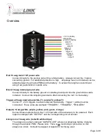
background image

Specifications 

Operating Voltage: 

6-20V for 12V systems 

Total Current Capacity: 

60 Amp maximum continuous 

Outputs: 

6 (20A Max) High side outputs 

Inputs (Triggers): 

3, voltage or ground configurable inputs 

Operating Temperature: 

-40 to 185°F / -40 to 85°C 

Connections: 

Sealed 18 inch hardwire leads

Water Protection:  

Fully encapsulated waterproof 

Weight: 

10 oz / 284 g 

Dimensions: 

3.0 x 2.0 x 0.9 in. / 76.2 x 50.8 x 22.9 mm

Package Contents

· 

1 -  Amplink Power Distribution Module

· 

1 -  Ground bus kit with cover 

· 

6 -  

¼” ring terminal – for use on accessory ground wires connected to the ground bus 

· 

1 -  6MM bolt & nut - used for connecting all accessory ground wires to the main ground bus          

· 

6 -  Posi-Lock Connectors 

– for easy and secure connections of 14 or 16ga wires 

· 

3 -  Posi-Tap Connector 

– for easy connection to any 18ga wire for triggering

The Amplink PDM is built on the strong reputation of the original PDM60 with added and improved 
features to make 12V power distribution even easier.   

User Manual

Page 1 of 8

Summary of Contents for Amplink PDM

Page 1: ...2 x 50 8 x 22 9 mm Package Contents 1 Amplink Power Distribution Module 1 Ground bus kit with cover 6 ring terminal for use on accessory ground wires connected to the ground bus 1 6MM bolt nut used fo...

Page 2: ...T3 Connect 1 2 or 3 triggers to achieve desired functionality Trigger 1 white must be connected These wires are stamped TRIGGER1 TRIGGER2 TRIGGER3 Outputs 14 awg white purple yellow pink green orange...

Page 3: ...od Note Before completing a full installation of your Amplink we recommend bench testing to ensure your setup functions as desired Amplink PDM App Page 3 of 8 The app is designed to be simple and stra...

Page 4: ...dicated by the green LED 2 If this is your first time connecting a Bluetooth device to the Amplink PDM proceed to step 3 or skip to step 9 if you ve already setup your device to pair with the Amplink...

Page 5: ...ettings including output name amperage limit delay on delay off trigger logic and or Tap the output name to open the output configuration screen Tapping Back will save and exit the configuration scree...

Page 6: ...er 3 Off Trigger 2 Off Voltage ve Disabled Disabled Outputs Output 1 Output 2 Output 3 Output 4 Output 5 Output 6 Monitor Setup Triggers Information Configure the trigger page as shown then proceed to...

Page 7: ...the Setup page by tapping Setup on the bottom of the screen Monitor Setup Triggers Information On the Setup page tap each output to open the configuration page In the Configuration page for output 1...

Page 8: ...or warranty claims This warranty covers parts and our labor for those parts to be replaced or repaired at a service facility we designate Please contact your dealer or Rowe Electronics Inc Specific di...

Reviews: