background image


FO-FDHB5-N-2007-08 


FO-FDHB5-N 

Internal Blower for Delta, Onyx, Opel 


The internal blower kit will increase the circulation of heated air generated by the fireplace into the room 
where it is installed. If you desire to distribute the heat in different rooms, please refer to central heating 
and zone heating kits (FO-FDHB6-1, FO-FDHC6, FO-FDHCZ1 and FO-FDHCZ2). 

All wiring should be in accordance with local ordinances and the National Electric Code. 

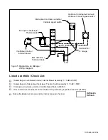
One thermal switch is all that is required to operate the internal blower, the central heating blower or 
both. If the thermal switch is already installed, skip to the installation of the internal blower. 

INSTALLATION ON A DELTA 

Installation of the thermal switch assembly 

1.  Remove the bottom central and right louvers. 

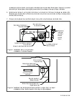
2.  The thermal switch goes in the middle of the central bottom louver opening, on the flange at the 

back of the shield below the firebox, with the thermal switch facing upwards (see Figure 1). Make 
sure to push the “S” clips onto the flange as far as they will go.  

Installation of the internal blower assembly 

3.  Pass the blower through the bottom louver opening so that the outlet is on the bottom and facing 

towards the back (see Figure 1). 

4.  Slide the blower between the two centering brackets on the fireplace base. 

INSTALLATION ON AN ONYX OR OPEL 

Installation of the thermal switch assembly 

1.  Open the bottom louver. 

2.  Under the firebox, on the left of the right firebox leg, you will find a welded bracket (see Figure 2). 

Install the thermal switch on that bracket, with the thermal switch facing upwards. Make sure to 
push the “S” clips onto the flange as far as they will go. 

If you have an ash pan in your fireplace, make sure that it is still possible to remove the ash pan 
once the thermal switch is installed. 

Installation of the internal blower assembly 

3.  Remove the vibration rubber dampers at both ends of the blower and reinstall them on both ends of 

the central support (see Figure 3). 

4.  If your fireplace is equipped with an ash pan: remove the ash pan plug, remove the ash pan and 

then remove the ash pan support by unscrewing the screw located at the back of the support. 

Summary of Contents for FO-FDHB5-N

Page 1: ...sh the S clips onto the flange as far as they will go Installation of the internal blower assembly 3 Pass the blower through the bottom louver opening so that the outlet is on the bottom and facing towards the back see Figure 1 4 Slide the blower between the two centering brackets on the fireplace base INSTALLATION ON AN ONYX OR OPEL Installation of the thermal switch assembly 1 Open the bottom lo...

Page 2: ...n the terminal block as indicated by the wire markers at the end of each wire 2 Connect each of the blue wires from the blower to the appropriate terminals 3 and 6 on the terminal block as indicated by the wire markers at the end of each wire 3 Install the variable speed switch in a regular 2 x 4 electrical box in a convenient location outside the fireplace 4 Using conventional 2 14 gauge wires co...

Page 3: ...doit être installé au centre de l ouverture de la persienne centrale sur le rebord arrière de l écran sous la boîte à feu avec l interrupteur thermique faisant face vers le haut voir Figure 1 Assurez vous de pousser les agrafes en S sur le rebord le plus loin possible Installation de l assemblage du ventilateur interne 2 Insérez le ventilateur à travers l ouverture de la persienne centrale de faço...

Page 4: ...ifié Enlevez la vis glissez la partie arrière par dessus la partie avant et vissez les ensemble Si un jour vous retirez le ventilateur de votre foyer vous devrez rallonger l écran radiant de plancher 10 Réinstallez le support magnétique de la persienne inférieure 11 Replacez le support du tiroir à cendres le tiroir à cendres et le bouchon de tiroir à cendres CABLÂGE POUR TOUS LES FOYERS voir Figur...

Page 5: ... fils de façon à ce qu ils ne touchent pas à la boîte à feu Tiroir à cendres Ash pan Équerre soudée Welded bracket Patte droite de la boîte à feu Right firebox leg Interrupteur thermique Thermal switch Bloc de borne Terminal block Figure 2 Installation de l interrupteur thermique dans un foyer Onyx ou Opel Installation of the thermal switch in an Onyx or Opel fireplace Interrupteur thermique Therm...

Page 6: ...let pointing up centrale Bottom central louver Figure 4 Installation du ventilateur dans un foyer Onyx ou Opel Installation of the blower in an Onyx or Opel fireplace Amortisseurs de vibrations Vibration rubber dampers Figure 3 Préparation du ventilateur pour une installation dans un foyer Onyx ou Opel Preparation of the blower for an installation in an Onyx or Opel fireplace ...

Page 7: ...enant 4 connecteurs en fourchette 1 Bag containing 4 spade connectors 942006 Notice d installation et liste de contrôle Instructions and check list INITIALES INITIALS Interrupteur de vitesse variable Variable speed switch Optionnel interrupteur manuel Optional manual bypass switch 110V Calibre 14 14 Gauge Interrupteur thermique Thermal switch Ventilateur interne Internal blower Bloc de borne Termi...

Reviews: