background image

RSF-IIN_12-05

Keep these instructions for future use.

The

ONYX AP

Owner's Manual

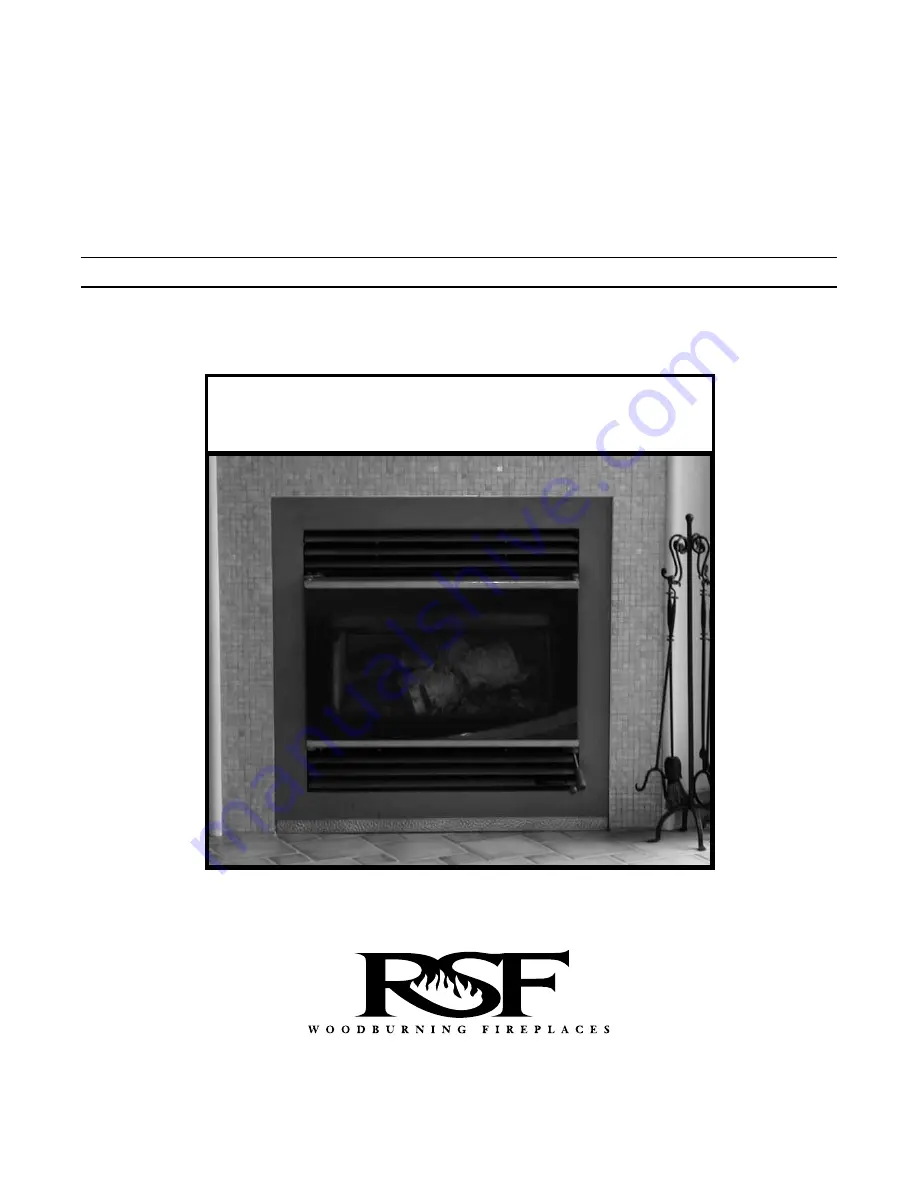
Residential Factory Built Fireplace

Operation  •  Maintenance  •  Installation

Summary of Contents for ONYX AP

Page 1: ...RSF IIN_12 05 Keep these instructions for future use The ONYX AP Owner s Manual Residential Factory Built Fireplace Operation Maintenance Installation ...

Page 2: ... Venting 20 The Gravity Vent System 21 The Central Heat System 26 Zone Heating 26 Gas Log Option SCHEMATIC WIRING DIAGRAMS 28 Thermostat 28 Circulating Blower 29 Central Heat System 29 All Systems 30 Zone Heating ONYX AP FIREPLACE OPTIONS 31 REPLACEMENT PARTS 32 Fireplace 33 Assemblies LABEL 34 WARRANTY 35 Dear Customer The ONYX AP fireplace incorporates technology with elegance to give you a beau...

Page 3: ...OTE Formation and removal When wood is burned slowly it produces tar and other organic vapours which combine with expelled moisture to form creosote The creosote vapours condense in the relatively cool chimney flue of a slow burning fire As a result creosote residue accumulates in the flue lining When ignited this creosote makes an extremely hot fire The chimney should be inspected periodically du...

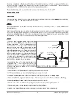
Page 4: ...e The louvers can be easily opened by pulling the right hand side of the louvers It is held in place by a magnet Remove ash pan and dispose of ashes properly Replace ash pan and louvers Replace plug in hole making sure it is properly placed before starting a fire Do not remove the ashes from the firebox while they are still hot The ash pan is not built to resist hot ashes or embers Under no circum...

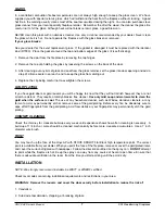
Page 5: ...ly sure to wipe off all fingerprints and debris from the gold plating The plating undergoes a sealing process during this first fire and the acid from your finger prints will permanently etch the gold plating You will experience a slow start up during the first fire The refractory bricks still contain moisture and take a good hot fire to get rid of the moisture While there is moisture in the brick...

Page 6: ...n closing the door Note how the locations of the pins vary as you turn them The hinges are adjustable by loosening the bolts holding the hinges and sliding the hinges backwards or forwards After adjustment tighten the bolts Make sure the door is square with the face of the Onyx AP before tightening the hinge bolts If the door seal is damaged to the point where it does not seal tightly replace it T...

Page 7: ...ll not tarnish however they are not scratch resistant They require a totally abrasive free cleaner Use only mild soap and warm water to clean the gold when the surface is cool The use of any household cleaner such as Windex abrasive cleaners or any form of acid may permanently etch or remove some of the gold plating Before every fire be absolutely sure to wipe off all fingerprints from the gold pl...

Page 8: ...of opening Electrical knockouts 5 wide sheet metal spark guard Storm collar Roof flashing Radiation shield and storm collar Ceiling Radiation shield Central heat blower Header See the manual for flue height requirements Gravity vents may be installed on the left right or both sides The central heat blower may be installed on the left or right side but not both Beneath hearth extension see page 16 ...

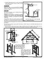
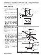
Page 9: ... above the fireplace DO NOT bring any combustible material lower than the top of the stand off 1 Note the location of floor and roof joists Choose a location which does not require cutting the joists Note the location of doors and windows in relation to the fireplace and chimney on all floors of the house ONYX AP Owner s Manual RSF Woodburning Fireplaces 9 Figure 3 Standoff installation Rear corne...

Page 10: ...of both the floor and ceiling levels to allow room air to circulate through the fireplace enclosure and reduce heat build up These vent grilles may be placed vertically or horizontally Under no circumstances is the distance between the first firestop and the top of the unit to be less than 33 inches See Figure 2 OUTSIDE AIR DUCT After the fireplace is correctly positioned connect the combustion ai...

Page 11: ...allows many options for instal lation Figure 7 is just one example When you build a close clearance installation remember that there must be 1 clearance along the back of the fireplace 1 2 along the sides of the fireplace and 4 1 2 on top of the fireplace No combustibles should move within these boundaries CHIMNEY This fireplace is certified for use with 7 ICC Model EXCEL chimney The chimney syste...

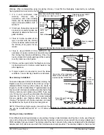
Page 12: ...s higher than 5 ft above the roof it must be secured using a roof brace 4 Put the roof flashing into place Seal the joint between the roof and the flashing with roofing tar For sloping roofs place the flashing under the upper shingles and on top of the lower shingles Nail the flashing to the roof using roofing nails 5 Place the storm collar over the chimney and flashing Seal it with silicone seale...

Page 13: ...ecured in place using a FDM If you use a 6 x 10 clay liner you will need to ovalize the stainless steel liner to fit into the clay liner It is recommended that you position your fireplace before building the chimney The factory built chimney sections can easily be installed as the layers of brick are being placed NOTE If the ceiling is high enough some vertical chim ney can be installed before the...

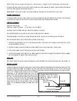
Page 14: ...st two screws For chimneys with less than 10 X 10 inside you may find it easier to install a flex liner and secure the end with a special adapter part LAF available from your dealer 4 Move the fireplace forward enough to install the length of EXCEL chimney and then move the fireplace back into position as you connect the masonry adaptor to the EXCEL chimney CHASE ENCLOSURE If the chimney runs up t...

Page 15: ... Secure each joint with 3 metal screws 3 Use another elbow to return the chimney to the vertical direction 4 Install a roof support wall support or an offset support at each offset to support the weight of the flue elbows are not designed to support a flue above an offset SEALING Be sure to seal the 1 4 space between the fireplace and the standoffs with a bead of silicone sealer See Figure 15 SPAR...

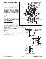
Page 16: ...fireplace door opening There is no minimum thick ness required for the hearth extension MANTEL A masonry or other non combustible mantel may be placed directly above the top louvers If a wood or other combustible mantel is desired it must be at least 14 inches above the top of door See Figure 14 15 No combustible materials behind sheeting below this line 5 1 2 max Header 12 max 12 max Silicone sea...

Page 17: ...n warm air movement to rooms serviced by the gravity vent If you desire even heat throughout your home strictly from your fireplace or if you want to move heat to a remote area of your home it is recommended that you incorporate the central heat option parts FDHB6 FDHC6 and FDHC6 1 A thermostatically controlled blower takes heat from the fireplace and distributes the warm air throughout your home ...

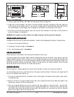
Page 18: ... is installed during framing so that the wiring can be easily hidden 1 Remove the bottom louver See operation 1 in the above section Pull the louver from the right hand side toward you Lift the louver to remove the bottom of the hinge rod from its hole Remove the top of the hinge rod from the top hole 2 Remove the ash pan To accomplish this you will need to remove the plug from the inside of the f...

Page 19: ...res 19 20 IMPORTANT Make certain that the 1 4 space between the finishing trim and unit is sealed with silicone sealer before installing the rock retainer kit WARNING DO NOT RESTRICT AIRFLOW THROUGH THE INLET AND OUTLET LOUVERS OF THE FIREPLACE NOTE Remove the louvers and leave the door wrapped in the shipping plastic Store them in a safe place until all the masonry work is finished Acid from the ...

Page 20: ...e A grille adaptor A B vent starter section A shut off damper IMPORTANT No substitution of any of these parts is allowed These genuine RSF Woodburning Fireplaces parts have the cor rect clearances These clearances must be maintained for your safety The FDVO system incorporates standard 8 B vent components for installation Single wall pipe is not allowed due to the high temperature of the air in a ...

Page 21: ...ace 6 Install the shut off damper at the base of the starter section The shut off damper enables the manual control of hot air flowing through the gravity vent pipe With the top louvers removed and the angular portion of the rod in hand insert the damper rod into the hole in the starter section Next make sure that the washer and spring on the control arm are both on the outside of the starter sect...

Page 22: ...king sure it is pushed all the way down Bend out the tabs on the lower edge of the damper at 4 places inside the fireplace with a pair of pliers so the back draft damper can not be pulled out again 4 Before proceeding with the installation of the blower make sure that the electrical service to the blower is in the OFF position All wiring should be in accordance with local ordinances and the Nation...

Page 23: ...d or flex Any other size will not work properly Use only metal ducting between the fireplace and the blower You may use plastic ducting after the blower provided the temperature rating of the ducting is at least 250 F Do not use plastic ducting in a chase NOTE The central heat ducting may be run at a 0 clearance to combustibles 7 Attach the noise reduction collars to the blower using self tapping ...

Page 24: ...o existing ductwork must be down stream from the existing furnace NOTE When the central heating blower is in operation it removes air from the room containing the fireplace If this room can be closed off from the rest of the house e g with a door a grille with at least a 100 square inch open area must be installed to allow the air to return to the fireplace Otherwise periodic smoking from the fire...

Page 25: ...thermostat in the room with the fireplace this is a less common use of the central heat blower Connect the wire from 4 of the terminal block to the red wire and put the marrette connector on the black wire for protection See Figures 37 and 38 for schematic wiring diagrams Figure 29 shows some ways of ducting the hot air from the blower You are not restricted in the size of pipe as long as the tota...

Page 26: ...yx AP for use with the gas log option 1 You will notice a 1 1 4 diameter knockout on both sides of the Onyx AP about 9 up from the bottom of the fireplace The gas line will be installed through one of these knockouts Choose the side that is best for your installation 2 Remove the firebrick from the base of the firebox You will notice two sheet metal pieces underneath the fire brick Remove these al...

Page 27: ...put 40 000 BTU There are no minimum clearances to the sides or top of the firebox However any clearances stated by the gas log set manufacturer must be maintained You may install the gas valve inside the firebox if the gas log set manufacturer allows this in its instructions and the required clearances are met ONYX AP Owner s Manual RSF Woodburning Fireplaces 27 Figure 34 The gas log option Rear r...

Page 28: ...aft damper motor Draft damper ther mostat 110V black white Figure 36 Wiring for the circulating blower Bare Thermal switch bypass optional Internal blower Thermal switch Terminal block Blower speed control 110V black white ONYX AP Owner s Manual RSF Woodburning Fireplaces 28 ...

Page 29: ...te yellow white white Bare black For a warming thermo stat 1 should be the red wire and 2 should be the black wire For a cooling thermo stat 1 should be the black wire and 2 should be the red wire External central heat blower Central blower speed switch Blower control thermostat Internal blower control Draft damper thermostat Draft damper motor Transformer Internal blower Thermal switch 18 ga LVT ...

Page 30: ...er motor Transformer Internal blower Thermal switch Terminal block black white white black yellow black Bare 110 V white 24 V Internal blower speed control External blower control 18 ga LVT External central heat blower Figure 39 Wiring for all systems with a zone heat system ONYX AP Owner s Manual RSF Woodburning Fireplaces 30 ...

Page 31: ... AP FIREPLACE OPTIONS FDHC4 Wall Thermostat FDHB5 Circulating Internal Blower FDVO Gravity Vent FDHB et FDHC6 Central Heating FDKO Rock Retainer Kit Note ONYX AP Owner s Manual RSF Woodburning Fireplaces 31 ...

Page 32: ... centre Secondary air tube front Secondary air tube rear Face stand off assembly Stand off top Terminal block assembly Terminal block Terminal block cover 1 5 3 NPT 1 5 2 N 10 1 NPR 10 11 NPR 10 21 NPR 99 10 04 N 14 3 52 14 9 2 14 5 3 14 8 5 10 2 NP 10 12 NP 10 22 NP 10 6 N 10 16 N 10 26 N 99 10 05 N 14 1 64 14 3 52 14 3 54 14 8 5 10 3 NP 1 10 3 NP FDGRK1 14 7 3 1 9 3 NR 1 9 6 NR 98 09 01 N 98 09 ...

Page 33: ... centre Secondary air tube front Secondary air tube rear Face stand off assembly Stand off top Terminal block assembly Terminal block Terminal block cover 1 5 3 NPT 1 5 2 N 10 1 NPR 10 11 NPR 10 21 NPR 99 10 04 N 14 3 52 14 9 2 14 5 3 14 8 5 10 2 NP 10 12 NP 10 22 NP 10 6 N 10 16 N 10 26 N 99 10 05 N 14 1 64 14 3 52 14 3 54 14 8 5 10 3 NP 1 10 3 NP FDGRK1 14 7 3 1 9 3 NR 1 9 6 NR 98 09 01 N 98 09 ...

Page 34: ... products be installed and serviced by professionals who are certified in the U S by NFI National Fireplace Institute or in Canada by WETT Wood Energy Technical Training ONYX AP Owner s Manual RSF Woodburning Fireplaces 34 ...

Page 35: ...ents necessitated by vandalism neglect abuse over firing improper fuel or fuel loads or failure to ade quately service the unit as stated in the owner s manual Repairs or replacements particularly charges for travel and labor not authorized by RSF Woodburning Fireplaces in advance LIMITATIONS All items found to be defective will be replaced or repaired upon return of the defective part to an autho...

Reviews: