background image

TIG401 AC/DC TIG WELDER 

OPERATION INSTRUCTIONS 

www.r-techwelding.co.uk 

Summary of Contents for TIG401

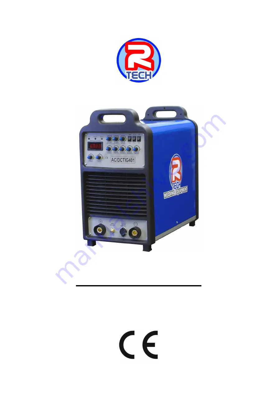
Page 1: ...TIG401 AC DC TIG WELDER OPERATION INSTRUCTIONS www r techwelding co uk ...
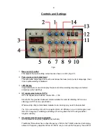
Page 2: ...2 ...

Page 3: ...n can be found on the data plate at rear of machine Product TIG401 Serial No ___________________________________ Date of Purchase _____________________________ Where Purchased _____________________________ Whenever you request replacement parts or information on this equipment please always supply information you have recorded above This product is covered by a 2 year parts and labour warranty we ...

Page 4: ...rom overloads beyond the output ratings and duty cycle as per machine specifications with thermostat protection of the output coils and rectifiers Welding Capability Duty Cycle The R Tech Tig401 is rated at 400 Amps at 60 duty cycle on a ten minute basis If the duty cycle is exceeded a thermal protector will shut machine off until the machine cools Technical Specifications Model No R Tech TIG401 I...

Page 5: ...particles towards the welder An abundance of conductive material can cause plant failure Stacking This machine cannot be stacked Transport Unloading Never underestimate the weight of equipment never move or leave suspended in the air above people Use recommended lifting equipment at all times WARNING Falling Equipment can cause injury Never lift welder with gas bottle attached Never lift above per...

Page 6: ...g these contributing factors in mind installing equipment as per following instructions should minimize problems 1 Keep the welder input power lines as short as possible and enclose as much of them as possible in metal conduit or equivalent shielding There should be a good electrical contact between this conduit and ground Earth 2 Keep the work and electrode leads as short as possible Tape the lea...

Page 7: ...pment Do not touch electrically live parts The TIG401 Inverter Tig Welder requires a 415V 50 60Hz 3 Phase supply It requires a 20A supply It comes with a 3 metre mains cable attached Connect wires according to national coding Brown wire Live Blue wire Neutral Green Yellow Wire Earth Ground Connecting to a mains electrical supply THIS MACHINE IS OF AN INDUSTRIAL SPECIFICATION AND MUST BE FITTED TO ...

Page 8: ...ls etc 3 Fuse Holder 3A fuse for water cooling socket 4 Mains input cable Fit required plug as per your electrical installation 5 Gas input connector Connect input gas hose ensuring connection is tight 6 Earth for chassis If experiencing localized interference when using machine connect workbench to this point using correct graded earth wire not normally used ...

Page 9: ...g until tight 4 Torch control socket 7 Pin Connect torch control plug To avoid a High Frequency shock keep the Tig torch in good condition and replace if any of the insulation is damaged Connect the gas input hose to gas regulator and use Pure Argon Gas available from local suppliers Set the gas flow pressure to 8 12 LPM Make sure gas bottle is secured to avoid injury Remote Foot Pedal connection ...

Page 10: ...W Welding Fig 3 1 Positive power connector Connect the electrode holder by inserting and twisting until tight 2 Negative power connector Connect the earth lead to by inserting and twisting until tight and the earth clamp to work bench ...

Page 11: ...ntrol 30 70 Set at 50 this provides balanced control suitable for most AC Welding 30 is max cleaning and 70 is max penetration When welding dirty contaminated material more cleaning may need to be selected Tip If you are welding close to the tungsten limits I E 200amps on a 2 4mm tungsten and the end of tungsten is wobbling and falling off turning down the SP will give better tungsten stability 5 ...

Page 12: ...taminated Note Gas pre flow time is fixed at 0 5 seconds in TIG mode but no pre flow time will occur if the arc is restarted during post flow time as gas is already flowing 11 MMA TIG mode switch MMA TIG mode switch Switches between TIG GTAW MMA STICK SMAW welding 12 AC DC Selector switch This switch selects either DC for welding steels or AC for welding alloys DO NOT SWITCH WHEN WELDING AS DAMAGE...

Page 13: ... shield gas after a 0 5 seconds pre flow time to purge air from torch hose the welding output of machine will be turned on and the arc will be started After the arc is started the output current will be at start min current This condition can be maintained as long as required Release the tig torch switch to go to step 2 The machine will now increase output to base main current in time set by slope...

Page 14: ...an be dangerous Keep your head out of fumes gases produced from welding Use ventilation or exhaust to remove fumes gases from breathing zone and general area WARNING WELDING SPARKS can cause fire or explosion Keep flammable material away from work area Do not weld on containers that have held combustibles WARNING ARC RAYS can burn Wear eye ear and body protection Make sure work area is protected b...

Page 15: ... setting 10 Adjust Pulse freq to desired setting 11 If welding on AC set AC Frequency to 100Hz and SP to 50 12 Press the Tig torch switch to start welding Notes When welding with Pulse the pulse amperage must be set higher than the base amperage The LED display will show Pre set amperage with base and pulse current settings The benefits of pulse welding is the ability to control the weld pool and ...

Page 16: ...ore welding Tips for AC Welding The TIG401 offers two significant advantages over conventional silicon rectifier SCR transformer power sources 1 The AC square wave balance SP can be set to a higher percentage electrode negative decrease below 50 which minimizes tungsten heating and erosion 2 The AC square wave frequency can be varied to focus the arc and achieve quicker travel speed Increasing the...

Page 17: ...0 4 8mm 3 16 500 750 300 280 390 6 4mm 1 4 750 1000 400 360 525 Welding in STICK MMA SMAW Mode 1 Fit MMA electrode holder to machine 2 Fit earth lead to machine and to work piece 3 Select MMA on MMA TIG switch 4 Select DC or AC DC is most commonly used 5 Place electrode in holder 6 Select desired welding base current 7 Select desired Arc Force 8 Strike arc and weld WARNING ELECTRIC SHOCK CAN KILL ...

Page 18: ...torch and cables in good condition 4 Clean air vents to ensure proper air flow and cooling 5 The fan motor has sealed bearings which requires no maintenance Troubleshooting Service repair should only be performed by R Tech welding trained personnel Unauthorised repairs performed on this welding equipment may result in danger or injury to the technician and machine operator and will invalidate your...

Page 19: ...achine keeps overheating Warning light is lit on machine Check if fan is running if not contact R Tech for repair Check the cooling vents for obstruction blow out machine with clean dry low pressure air supply Check for adequate ventilation around machine Porosity in weld No low gas at torch tip Check gas supply from gas bottle Check flow rate on regulator Check gas hose for restrictions Check for...

Page 20: ...as hoses Black areas along weld bead 1 Clean any oily or organic contamination from the work piece 2 Tungsten electrode contaminated Replace or sharpen 3 Check for leaks or contamination on gas hoses connections 4 Gas flow may be insufficient Increase gas flow reduce tungsten stick out from ceramic Weak HF Poor arc striking welding output normal 1 Check torch and earth connections is torch cable i...

Page 21: ...odes or material Electrode sticks in weld puddle Welding current is set too low Arc is too short keep electrode further away from work Excessive splatter Too long an arc keep electrode closer to work Poor penetration Travel speed too fast Too much welding current reduce welding amperage Porosity in weld Electrodes are damp Arc too long get electrode closer to work ...

Page 22: ...22 ...

Page 23: ...23 ...

Page 24: ...24 ...

Reviews: