Copyright © 2013 Ruckus Wireless, Inc.
Published June 2013, Part Number 800-70456-001 Rev D
Page 1 of 2
ZoneDirector
™
5000 and
SmartCell Gateway
™
200
Rack Mount Installation Guide
This
Rack Mount Installation Guide
provides step-by-step
instructions on how to install the Ruckus Wireless ZoneDirector
5000 or SmartCell Gateway 200 (SCG) into a server rack. Both
ZoneDirector 5000 and SCG are standard 2U form factor
designed for mounting in a standard EIA 19” server rack.
B
EFORE
Y
OU
B
EGIN
Before deploying your Ruckus Wireless product, verify that all
items listed in “Package Contents” below are included in the
package. If any item is damaged or missing, notify your
authorized Ruckus Wireless sales representative. Also, ensure
that you have prepared the required hardware and tools.
T
HIS
G
UIDE
IN
O
THER
L
ANGUAGES
请从以下网站获得该指南的简体中文版
https://support.ruckuswireless.com
.
Vous trouverez la version française de ce guide à l'adresse suivante
https://support.ruckuswireless.com
.
こ の ガ イ ド の⽇本語版は
https://support.ruckuswireless.com
で ご覧 く だ さ い。
이
가이드의
한국어
버전은
웹
사이트
(
https://support.ruckuswireless.com
)
에서
확인하시기
바랍니다
.
Veja a versão em português (Brasil) deste guia em
https://support.ruckuswireless.com.
Puede ver la versión en español (América Latina) de esta guía en
https://support.ruckuswireless.com.
R
EQUIRED
H
ARDWARE
AND
T
OOLS
•
3/8-inch hex driver or wrench
•
Phillips (crosshead) screwdriver, #1 and #2 bits
•
Anti-static wrist strap and conductive foam pad
(recommended)
P
ACKAGE
C
ONTENTS
A complete rack mount installation kit includes all of the items
listed below:
NOTE: This kit includes two sets of 8-32 x 1/2" screws. One set
of eight has a larger screw head size than the second set of
eight. Use the set of 8-32 x 1/2" screws that best fits the rack in
which you are installing the rail kit.
•
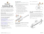
Outer rail slide assembly (see A in Figure 1)
•
Inner rail slide assembly (see B in Figure 1)
•
Plastic bag #1, which contains the following items:
- Four hex head shoulder screws (see A in Figure 4)
- Two rack mounting ears (see A in Figure 7)
- Two #10-32 x 3/8” screws (see B in Figure 7)
•
Plastic bag #2, which contains the following items:
- Outer slide rail screws, 8 #8-32 x 1/2 (see D in Figure 1)
- Inner slide rail screws, 8 #6-32 x 1/4 (see D in Figure 1)
- Rack screws, 2 #8-32 x 3/4 (see D in Figure 1)
•
This
Rack Mount Installation Guide
Figure 1: Rail assemblies and rail screws
S
TEP
1: S
EPARATE
THE
S
LIDE
R
AILS
INTO
THE
I
NNER
AND
O
UTER
P
ARTS
1
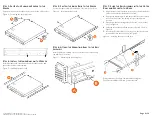
Extend the inner rail (see 1 in Figure 2) until it locks.
2
Press down the spring safety lock (see 2 in Figure 2) to
release the inner rail.
3
Remove the inner rail from the rail assembly (see 3 in Figure
2).
Figure 2: Separating the slide rails
S
TEP
2: I
NSTALL
THE
O
UTER
R
AIL
S
LIDES
TO
THE
R
ACK
P
OSTS
NOTE: The two rail assemblies that are included are NOT
interchangeable. Each assembly needs to be installed into the
rack by its orientation (right or left) when standing in front of the
rack. The right rail assembly is identified with a BLUE sticker and
the left rail assembly is identified with a GREEN sticker.
Attach the outer rail slides to the rack posts using two #8-32 x
1/2 screws at the front posts and two #8-32 x 1/2 screws at the
rear posts.
Figure 3: Installing the outer rails


