Photoelectric
Smoke Detector
TYPICAL WIRING DIAGRAM
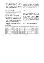
Figure 1.a shows the typical wiring diagram of 2-wire
multiple-station smoke detector system.
DO NOT USE LOOPED WIRE UNDER
TERMINALS 2 AND 5 BREAK WIRE RUN TO
PROVIDE SUPERVISION OF CONNECTIONS
Figure 1.b shows the typical wiring diagram of 4-wire
multiple-station smoke detector system.
DO NOT USE LOOPED WIRE UNDER
TERMINALS 2 AND 5 BREAK WIRE RUN TO
PROVIDE SUPERVISION OF CONNECTIONS
WARNING
TO PREVENT DETECTOR CONTAMINATION
AND
SUBSEQUENT
WARRANTY
CANCELL
A
TION,
T H E
SMOKE
DETECTOR MUST REMAIN COVERED
UNTIL AREA IS CLEAN AND DUST FREE.
INSTALLING THE BASE
1.
To insure proper installation of the detector
,
head to
the
base, all the wires should be properly
addressed at
installation:
(A)
Position all the wires flat against terminals.
(B)
Fasten the wires away from connector terminals.
2.
If you use the jumper wire to connect the poles of
terminal 2 and 5 when testing the detector
loop
's
continuity, be sure to remove the jumper wire
prior to
the installation of the detector head.
3.
The end-of-line device shown in Figure 1.a & 1.b
should be compatible with the control unit. The
end-of-line supervisory relay used should list the rated
DC power voltage used.
4.
Per UL listing, open area smoke detectors are
SF119 series
Installation Wiring Diagram
intended for mounting on a ceiling
at least
6 inches
away
from a wall or mounting on a wall
between
4
and
12 inches
away
from a ceiling.
5. The base of smoke detector can be mounted directly
onto
an
electrical junction box
:
octagonal (3”, 3.5”
or
4”), round (3”), and square (4” length) box
es
without
using any type of mechanical adapter
s
.
INSTALLING THE HEAD
1.
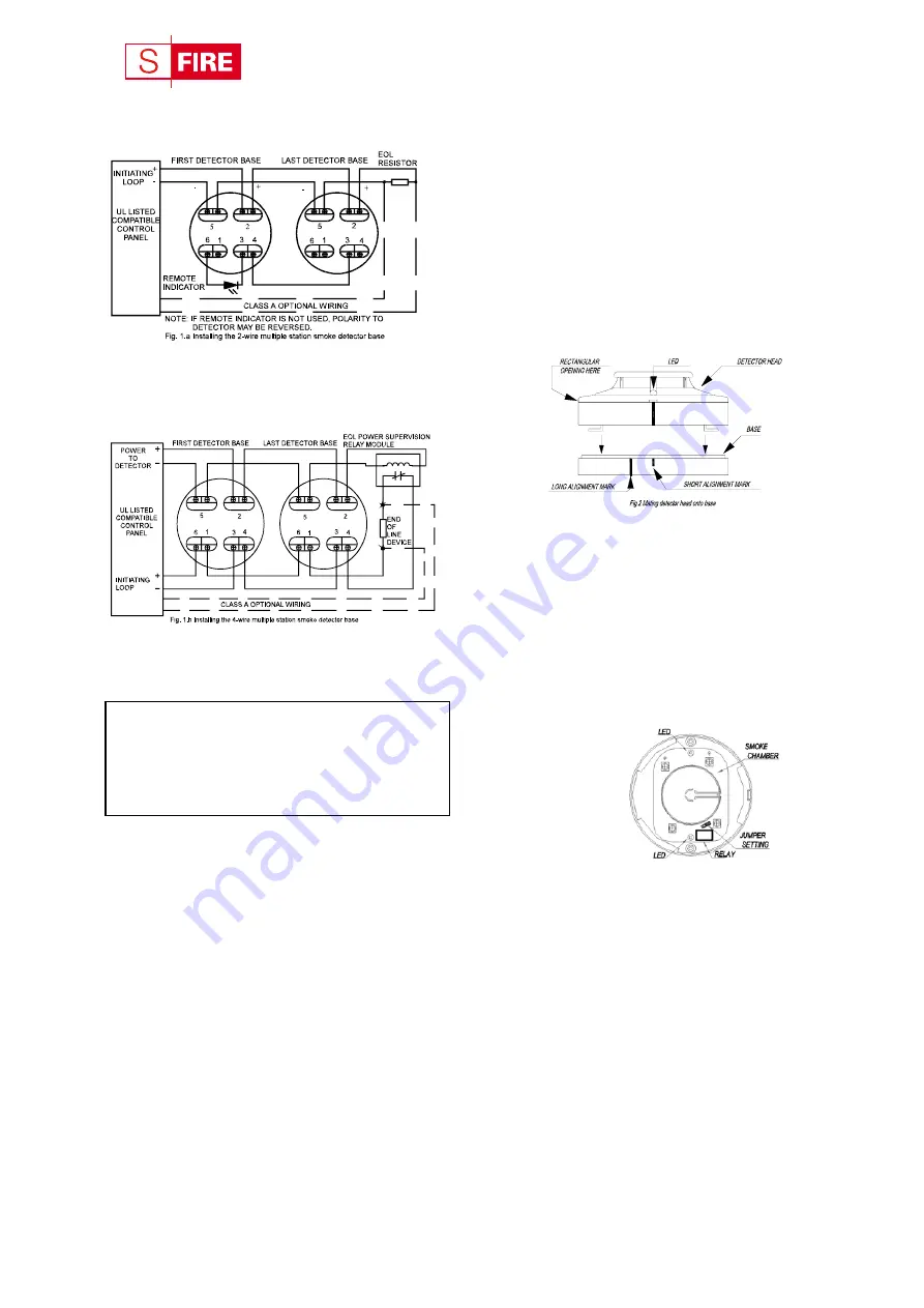
Align the components as shown in Figure 2.
2.
Mate the detector head onto the base and twist
it
clockwise to secure it.
3.
Do not install the detector head until the area is
thoroughly cleaned of construction debris, dusts, etc.
The maximum number of smoke detector installed in
the same loop is 30 units.
Fig. 2 Mating detector head onto base
ADJUSTMENT OF THE RELAY POSITION
4-wire type: Adjust the relay set-position for wiring unit to
the
security monitoring system
through
the following steps:
1. The reset position for the relays is “normal
ly
open”
(NO), when
powering
all the relays.
2.
3.
T
o adjust the relay set point, use a
screwdriver to
loose
n the
two screws on the back of the
base.
Figure 3
shows
a jump head next to the
relay on the
PCB, adjust it to select either
the
“normal
ly
close
d
” (NC) or
the
“normal
ly
open” (NO) position
s
.
Relay contact rating:
1A @30VDC,
0.5A @125VAC.
TESTING
1.
All the alarm signal services, releasing device and
extinguisher system should be disengaged during the
test period and must be re-engaged immediately at the
conclusion of testing.
2.
After
powering
the detector head for approximately
one minute, check
if the
red LED
light is
flashing
once every 1~3 seconds. If
the
red LED fails to
flash, it indicates
that
the detector
is not functioning
properly
or
the possibility of having incorrect
wiring.
Re-check the wiring or replace the
detector if
necessary.
Fig. 3 Schematic of detector structure
When front cover is open