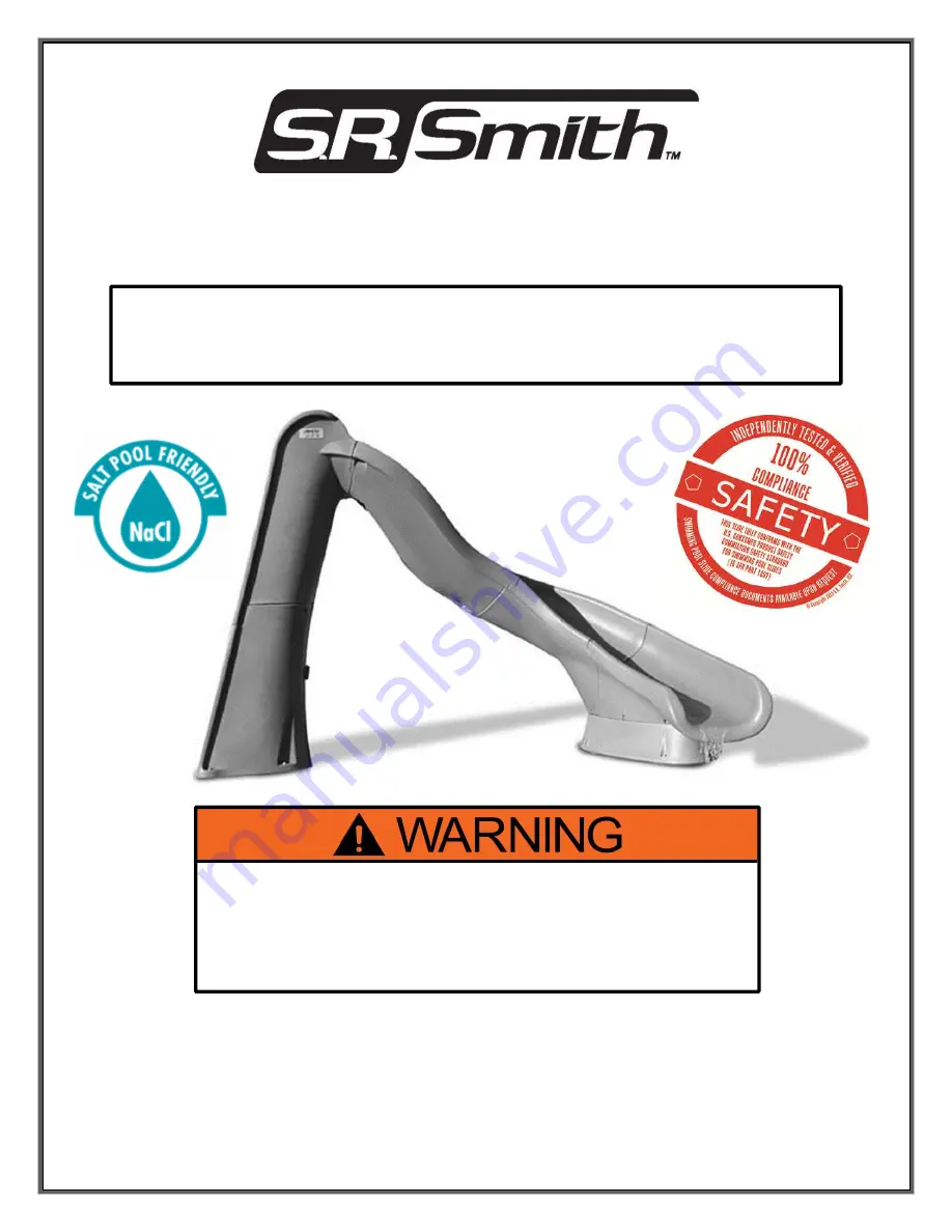
background image

06-693 


June16 


TURBOTWISTER® 

ASSEMBLY AND INSTALLATION 

INSTRUCTIONS 

SRS AUSTRALIA, PTY LTD 

12 Enterprise St 

Richlands QLD 4077 

Australia 

Phone 07 3812 2283 • Fax 07 3812 1187 

www.srsmith.com/au 


S.R. SMITH, LLC 

CORPORATE HEADQUARTERS 

P.O. Box 400 • 1017 S.W. Berg Parkway 

Canby, Oregon 97013 

USA 

Phone (503) 266 2231 • Fax (503) 266 4334 

www.srsmith.com 


S.R.  SMITH  TURBOTWISTER  SLIDES  ARE  MANUFACTURED  FOR 
INSTALLATION  AND  USE  ON  RESIDENTIAL  INGROUND  SWIMMING 
POOLS ONLY.  THE TURBOTWISTER IS NEVER TO BE INSTALLED AND 
USED ON ABOVEGROUND POOLS, ONGROUND POOLS, HOUSEBOATS, 
BOAT  DOCKS,  FLOATING  DOCKS  OR  PLATFORMS  OR  OTHER  BODIES 
OF WATER SUCH AS LAKES, PONDS, RIVERS, ETC. 

Summary of Contents for TURBOTWISTER

Page 1: ...ERS P O Box 400 1017 S W Berg Parkway Canby Oregon 97013 USA Phone 503 266 2231 Fax 503 266 4334 www srsmith com S R SMITH TURBOTWISTER SLIDES ARE MANUFACTURED FOR INSTALLATION AND USE ON RESIDENTIAL...

Page 2: ...PARTS LIST 7 MAIN SECTION ASSEMBLY 8 CONCRETE WEDGE ANCHOR MOUNTING INSTRUCTIONS 16 WATER SYSTEM PARTS LIST 18 WATER SYSTEM ASSEMBLY 19 MANUFACTURER S PLACEMENT INSTRUCTIONS 22 Visit srsmith com for i...

Page 3: ...ENTS FOR SIZE OF CONCRETE FOOTING OVERALL HEIGHT OF SLIDE AND BODING OR ELECTRICAL CODES CHECK INSIDE ALL BOXES AND PACKAGING MATERIALS FOR PARTS BEFORE BEGINNING ASSEMBLY READ ALL INSTRUCTIONS AND ID...

Page 4: ...pool equipment should be at least 3 6 1 067 M 6 Observe the position of the exit of the slide as shown in Figure W Figure X and Figure Z on pages 22 and 23 MAINTENANCE INSTRUCTIONS 1 When hosing down...

Page 5: ...5 ASSEMBLED TURBOTWISTER LAYOUT The left curve TurboTwister is shown for illustration The right curve TurboTwister is a mirror image of the left Figure A...

Page 6: ...in case any gasket has fallen off during shipping If gasket installation is required follow the instructions below in Figure B The gasket on the face of the ladder is not installed in the factory but...

Page 7: ...5 3 8 FLAT WASHER 35 ea 5 5 235 3 8 x 2 1 4 CARRIAGE BOLT 2 ea 6 5 236 3 8 x 2 1 4 BUTTON HEAD CAP SCREW 2 ea 7 5 249 3 8 x 3 1 4 BUTTON HEAD CAP SCREW 2 ea 8 5 239 3 8 x 2 1 2 STUD 4 ea 9 5 240 3 8 x...

Page 8: ...ht while fastening Note Ensure gasket material at the joint is intact before assembling The required hardware is as follows 3 8 x 5 Socket Head Cap Screw 10 3 8 Flat Washer 4 3 8 Flat Washer 4 3 8 Loc...

Page 9: ...s shown in Figure E The required hardware is as follows 3 8 x 6 Hex Head Cap Screw 11 3 8 Flat Washer 4 3 8 Flat Washer 4 3 8 Lock Washer 2 and 3 8 Hex Nut 1 4 Attach the Pedestal to the Middle Runway...

Page 10: ...ure G 6 Assemble the Top and Bottom Ladder Sections as shown in Figure H Figure I and Figure J Do not fully tighten fasteners until all the hardware is in place The hardware required for the connectio...

Page 11: ...igure I are as follows 3 8 x 3 1 4 Button Head Cap Screw 7 and 3 8 Flat Washer 4 8 The hardware required for the connections shown in Figure J are as follows 3 8 x 2 1 4 Carriage Bolt 5 3 8 Flat Washe...

Page 12: ...toward both sides Be sure that the bottom edge of the gasket material is held against the shelf on the ladder section during installation see Figure K Note Make the bend radius as large as possible wh...

Page 13: ...Lock Washer 2 and 3 8 Hex Nut 1 Notes Use caution to protect the ladder from being scratched during this step It is strongly recommended that a second person assist to help ensure that the Top Runway...

Page 14: ...way sidewall connections The required hardware is as follows 3 8 x 5 Socket Head Cap Screw 10 3 8 Flat Washer 4 3 8 Flat Washer 4 3 8 Lock Washer 2 3 8 Hex Nut 1 12 Install the fasteners on the unders...

Page 15: ...a 1 4 pilot hole through the center of the 6 circular indentations around the perimeter of the Pedestal Runway connection Then install a 3 8 x 3 1 2 Lag Screw 9 and 3 8 Flat Washer 4 as shown in Figur...

Page 16: ...nt on the concrete 4 In order to protect the slide from being damaged by the drill bit move the slide aside before drilling the holes into the concrete deck 5 Using a power drill and a 1 2 concrete dr...

Page 17: ...to place beneath the base of the Ladder to ensure it is plumb due to varying deck slopes Call S R Smith at 800 824 4387 if shims are needed 10 Expand the Wedge Anchor Stud 12 by tightening the Wedge A...

Page 18: ...ISTER HARDWARE CARTON 1 ea 15 5 242 14 x 1 PAN HEAD TAPPING SCREW 6 ea 16 05 787 2 PVC PIPE STRAP 2 ea 17 05 788 1 1 2 PIPE CLAMP 2 ea 18 05 789 2 1 1 2 PVC FLEX HOSE 6 0 LONG 1 ea 19 05 789 1 1 1 2 P...

Page 19: ...ve 20 Then insert the 1 1 2 Coupling 21 to the opposite end of the longer 1 1 2 Flex Hose 18 as shown in Figure R 2 Make alignment marks on the parts with a pencil before disassembling This will aid i...

Page 20: ...in Figure T 6 Secure the 1 1 2 Flex Hose 18 to the ladder with the two 1 1 2 Pipe Clamps 17 that were installed previously in Step 4 on page 19 7 Secure the 1 1 2 Ball Valve 20 with two 2 Pipe Straps...

Page 21: ...mbing assembly Extend the water supply stub up to a height of 18 above the deck It can be cut to the desired length later during the installation process 9 Attach the stub up to the plumbing assembly...

Page 22: ...minimum depth of water below the exit lip of the slide shall be 3 0 and increase to 4 6 at Point A which is a distance of 4 6 from the exit lip of the slide as shown in Figure W D A minimum depth of...

Page 23: ...OARD WIDTH AT PT C C The minimum clearance area of a slide or diving board shall not intersect any coping or rope and float line as shown in Figure Z The minimum clearance area of a slide or diving bo...

Reviews: