background image

Summary of Contents for UP-TOUCH

Page 1: ...04 21 cod 4051361 ISTRUZIONI PER L USO OPERATING INSTRUCTIONS GEBRAUCHSANWEISUNG MODE D EMPLOI INSTRUCCIONES DE USO UP UP TOUCH TOUCH UP UP ECO ECO...

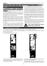
Page 2: ...per il montaggio dell unit di potenza quando non forniti installati da fabbrica Le unit base fornite senza comandi sono equipaggiate di morsettiera elettrica predisposta per il collega mento a regolat...

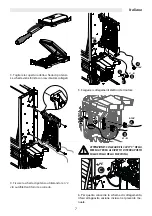
Page 3: ...2 viti autofilettanti fornite a corredo A B 0 10V L1 N C PE PE D1 D 5 Eseguire i collegamenti elettrici del motore C PE ATTENZIONE COLLEGARE IL CAVO C DELLA MESSA A TERRA AL RIVETTO DI TERRA POSTO SU...

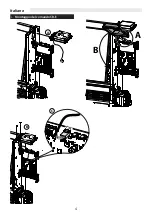
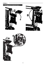
Page 4: ...4 Italiano Montaggio del comando CB E A B A B CTRL CTRL C...

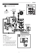
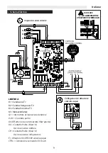
Page 5: ...ttuatore On Off 230V valvola acqua CTRL Connessione comando CB Touch L N EV L N L N PE PE DI1 0 0 10V N M4 M3 M10 M2 M5 M7 M6 M1 KD1 1 2 ON MC2 CLOSE ECO POWER UNIT ECO POWER UNIT M4 N EV N L PE N L Q...

Page 6: ...acqua superiore a 30 C evitando cos che dall apparecchio esca aria fredda Per migliorare il comfort inoltre possibile seleziona re la modalit di funzionamento notturno che riduce al minimo la velocit...

Page 7: ...di potenza utilizzando le n 2 viti autofilettanti fornite a corredo 5 Eseguire i collegamenti elettrici del motore C PE A 0 10V B L1 N PE D D1 PE ATTENZIONE COLLEGARE IL CAVO C DELLA MESSA A TERRA AL...

Page 8: ...8 Italiano Montaggio del comando CB Touch A B CTRL C CTRL B CTRL C CTRL A B...

Page 9: ...B1 Sonda aria T1 B2 Sonda change over T2 B3 Sonda di minima T3 M Motoventilatore Q1 Interruttore di manovra sezionatore 0 DI1 Contatto pulito On Off esterno cronotermostato Mc2 aperto BO Contatto Puli...

Page 10: ...nso funzionamento Chiller CTRL Connessione comando CB Touch 4 2 1 3 4 3 1 2 KD1 KD2 MC4 MC2 M3 M2 M1 D 0 7 6 5 6 0 D 10V 0 5 DI1 M8 M6 PE CH M10 EH BO BO CH M13 M11 PE N L EV N N N M12 L1 ON ON EVO PO...

Page 11: ...LA SONDA ARIA T1 ATTENZIONE Per un corretto funzionamento della sonda eseguire l installazione come indicato nelle istruzioni Collegare la sonda aria al connettore T1 sulla scheda di potenza CFF Posiz...

Page 12: ...modo automatico applicando sulla tuba zione acqua che alimenta la batteria la sonda Change Over T2 opzionale La sonda va posizionata prima della valvola a tre vie In base alla temperatura rilevata dal...

Page 13: ...nvettore nella versio ne IAQ accessorio Controllo del funzionamento resistenza elettrica quando montata come accessorio Attivazione Disattivazione della funzione Risparmio energetico Per qualsiasi man...

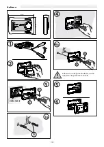
Page 14: ...14 Italiano 1 2 DIN 503 B1 B1 B B1 B1 3 3a 4 4a 28 mm C IAQ AUTO AUTO 135 mm 88 mm Effettuare i collegamenti elettrici come riportato nel presente manuale 5 6...

Page 15: ...O On Off Fig A Premendo il tasto ON OFF il comando viene acceso Premendo nuovamente il tasto ON OFF il comando viene spento C IAQ AUTO AUTO Fig A Impostazione del Set Fig B Impostare con la manopola i...

Page 16: ...onamento Estate il set point di lavoro impostato dalla manopola viene aumentato di 3 C In funzionamento Inverno il set point di lavoro impostato dalla manopola viene diminuito di 3 C C IAQ AUTO AUTO 6...

Page 17: ...porre i fori posizionare i tasselli nel muro e bloccare il pannello con viti Eseguire i collegamenti elettrici come indicato dallo schema elettrico riportato sulla pagina successiva ATTENZIONE Per ese...

Page 18: ...esto utiliz zando i tasti o Fig A Fig B Selezione modalit Fig C Premendo il pulsante M selezionare la modalit di funzionamento voluta viene impostata la funzione raffreddamento viene impostata la funz...

Page 19: ...rno 1 luned giorno 2 marted giorno 7 domenica Confermare con il tasto M Premere il tasto M per 3 secondi per uscire dal pro gramma O Fig E TIMER 1 Attivazione Disattivazione Fig F Premere il tasto M i...

Page 20: ...rno della settimana e il messag gio 00 00 Tramite i tasti o impostare l ora di accensione desiderata Confermare con il tasto M Il display visualizza il messaggio OF 1 ora di spe gnimento del primo gio...

Page 21: ...eamente per 3 secondi con il comando in OFF Scegliere il parametro desiderato premendo i tasti o e confermare con il tasto M Selezionato il parametro il display visualizzer il valore Per uscire dal me...

Page 22: ...Funzione Descrizione Range Default T3 1 Ventilatore ON in riscaldamento 30 40 C 36 C T3 2 Ventilatore ON in raffrescamento 10 25 C 22 C I T3 Isteresi sonda T3 2 6 C 4 C PARAMETRI Ciclo Antistratificaz...

Page 23: ...zione Non schiacciare il cavo in corri spondenza di pressatravi o supporti di sicurezza rispettare sempre la posizione dei colori in corrispon denza dei punti di partenza ed arrivo del collegamento un...

Page 24: ...ione scelte vedi manuale del comando MAX 16 tot L max 100m L max 20m Slave Slave Slave Master 5 6 7 MC4 MC2 M3 M2 M1 D 0 7 6 5 6 0 D 10V 0 5 DI1 EVO POWER UNIT ELETTRONIC POWER BOARD CFF AUTO MC4 MC2...

Page 25: ...power board Instructions for installing the power unit when not factory installed The basic units supplied without controls are equipped with an electrical terminal board prepared for connection to ex...

Page 26: ...board using the 2 self tapping screws supplied 5 Do the electrical motor connections WARNING CONNECT THE GROUNDING CABLE C TO THE GROUND RIVET ON THE SHOULDER OF THE MACHINE C PE A B 0 10V L1 N C PE...

Page 27: ...27 English Installation of the CB E control A B A B CTRL CTRL C...

Page 28: ...230 V water valve CTRL CB Touch control connection L N EV L N L N PE PE DI1 0 0 10V N M4 M3 M10 M2 M5 M7 M6 M1 KD1 1 2 ON MC2 CLOSE ECO POWER UNIT ECO POWER UNIT M4 N EV N L PE N L Q1 CB E MOUNTED CO...

Page 29: ...ing cold air from flowing out from the device To improve comfort it is also possible to select the night mode which minimises the fan speed and smartly changes the set temperature independently The co...

Page 30: ...oard using the 2 self tapping screws supplied 5 Do the electrical motor connections C PE A 0 10V B L1 N PE D D1 PE WARNING CONNECT THE GROUNDING CABLE C TO THE GROUND RIVET ON THE SHOULDER OF THE MACH...

Page 31: ...31 English Installation of the CB Touch control A B CTRL C CTRL B CTRL C CTRL A B...

Page 32: ...3 CTRL B KEY B1 Air probe T1 B2 Changeover probe T2 B3 Minimum probe T3 M Fan motor Q1 Disconnector control switch 0 DI1 ON OFF Clean contact outside the programmable thermostat MC2 open BO Clean cont...

Page 33: ...iller operation enabling CTRL CB Touch control connection 4 2 1 3 4 3 1 2 KD1 KD2 MC4 MC2 M3 M2 M1 D 0 7 6 5 6 0 D 10V 0 5 DI1 M8 M6 PE CH M10 EH BO BO CH M13 M11 PE N L EV N N N M12 L1 ON ON EVO POWE...

Page 34: ...OF THE T1 AIR PROBE WARNING For a correct operation of the probe perform the installation as indicated in the instructions Connect the air probe to the T1 connector on the CFF power board Position th...

Page 35: ...applying the ChangeOver T2 probe optional to the water pipe that supplies the coil The probe must be positioned upstream of the three way valve Depending on the temperature detected by the probe the d...

Page 36: ...essory Checking the operation of the electrical resistance when mounted as an accessory Activating deactivating the Energy Saving function For any maintenance make sure you have disconnected the power...

Page 37: ...37 English 1 2 DIN 503 B1 B1 B B1 B1 3 3a 4 4a 28 mm C IAQ AUTO AUTO 135 mm 88 mm Make the electrical connections as described in this manual 5 6...

Page 38: ...OF THE CONTROL On Off Fig A By pressing the ON OFF button the control is switched on Pressing the ON OFF button again the control is switched off C IAQ AUTO AUTO Fig A Setting the Setpoint Fig B Use...

Page 39: ...tion the working set point set by the knob is increased by 3 C In winter operation the working set point set by the knob is decreased by 3 C C IAQ AUTO AUTO 6 6a Fig F C IAQ AUTO AUTO IAQ 5 sec 3 7 Pu...

Page 40: ...ixing points Prepare the holes place the dowels in the wall and secure the panel with screws Maketheelectricalconnectionsasshowninthewiring diagram on the next page WARNING To make the electrical conn...

Page 41: ...t starts flashing Set the required temperature value using the or buttons Fig A Fig B Mode selection Fig C Press the M button to select the desired operation mode the cooling function is set the heati...

Page 42: ...ay 1 Monday day 2 Tuesday day 7 Sunday Confirm with the M button Press the M button for 3 seconds to exit the programme O Fig E TIMER 1 Activation Deactivation Fig F Press the M button the operation m...

Page 43: ...day of the week and the message 00 00 Use the or buttons to set the desired switching on time Confirm with the M button The display shows the message OF 1 switching off time of the first day of the w...

Page 44: ...e control in OFF Select the desired parameter by pressing the or buttons and confirm with the M button Once the parameter has been selected the display will show the value To exit the menu press the M...

Page 45: ...AMETERS TME minimum probe Function Description Range Default T3 1 Fan ON in heating mode 30 40 C 36 C T3 2 Fan ON in cooling mode 10 25 C 22 C I T3 T3 probe hysteresis 2 6 C 4 C Anti stratification cy...

Page 46: ...he cable carefully and carefully Do not crush the cable at the cable splices or safety supports always respect the position of the colours at the starting and finishing points of the connection once t...

Page 47: ...tings chosen see the control manual MAX 16 tot L max 100m L max 20m Slave Slave Slave Master 5 6 7 MC4 MC2 M3 M2 M1 D 0 7 6 5 6 0 D 10V 0 5 DI1 EVO POWER UNIT ELETTRONIC POWER BOARD CFF AUTO MC4 MC2 M...

Page 48: ...r le montage de l unit d alimentation lorsqu il n est pas fourni install en usine Les unit s de base fournies sans commandes sont quip es d une plaque bornes lectrique pr par e pour le branchement des...

Page 49: ...de des 2 vis auto taraudeuses fournies 5 Effectuer les branchements lectriques du moteur C PE A B 0 10V L1 N C PE PE D1 D A 0 10V B L1 N PE D D1 PE ATTENTION BRANCHER LE C BLE C DE LA MISE LA TERRE AU...

Page 50: ...50 Fran ais Montage de la commande CB E A B A B CTRL CTRL C...

Page 51: ...Off 230V vanne eau CTRL Branchement commande CB Touch L N EV L N L N PE PE DI1 0 0 10V N M4 M3 M10 M2 M5 M7 M6 M1 KD1 1 2 ON MC2 CLOSE ECO POWER UNIT ECO POWER UNIT M4 N EV N L PE N L Q1 CB E MOUNTED...

Page 52: ...sup rieure 30 C ce qui emp chera l air froid de sortir de l appareil Pour am liorer le confort il est galement possible de s lectionner le mode nocturne qui r duit la vitesse du ventilateur au minimum...

Page 53: ...e des 2 vis auto taraudeuses fournies 5 Effectuer les branchements lectriques du moteur C PE 5 ATTENTION BRANCHER LE C BLE C DE LA MISE LA TERRE AU RIVET DE MISE LA TERRE PLAC SUR LA JOUE DE LA MACHIN...

Page 54: ...54 Fran ais Montage de la commande CB Touch A B CTRL C CTRL B CTRL C CTRL A B...

Page 55: ...ENDE B1 Sonde air T1 B2 Sonde change over T2 B3 Sonde minimale T3 M Motoventilateur Q1 Interrupteur de man uvre sectionneur 0 DI1 Contact sec On Off externe chronothermostat Mc2 ouvert BO Contact sec...

Page 56: ...nt chiller CTRL Connexion commande CB Touch 4 2 1 3 4 3 1 2 KD1 KD2 MC4 MC2 M3 M2 M1 D 0 7 6 5 6 0 D 10V 0 5 DI1 M8 M6 PE CH M10 EH BO BO CH M13 M11 PE N L EV N N N M12 L1 ON ON EVO POWER UNIT T2 T1 T...

Page 57: ...SONDE AIR T1 ATTENTION Pour le bon fonctionnement de la sonde effectuer l installation comme indiqu dans les instructions Brancher la sonde air au connecteur T1 sur la carte d alimentation CFF Placer...

Page 58: ...matiquement en appliquant la tuyauterie d eau qui alimente la batterie la sonde change over T2 en option La sonde doit tre plac e avant la soupape trois voies En fonction de la temp rature d tect e pa...

Page 59: ...on IAQ accessoire Contr le du fonctionnement de la r sistance lec trique lorsqu elle est mont e comme accessoire Activation d sactivation de la fonction d conomie d nergie Pour tout entretien s assure...

Page 60: ...60 Fran ais 1 2 DIN 503 B1 B1 B B1 B1 3 3a 4 4a 28 mm C IAQ AUTO AUTO 135 mm 88 mm Effectuer les branchements lectriques comme d crit dans ce manuel 5 6...

Page 61: ...NDE On Off Fig A En appuyant sur la touche ON OFF la commande s allume En appuyant nouveau sur la touche ON OFF la commande s teint C IAQ AUTO AUTO Fig A R glage du point de consigne Fig B R gler l ai...

Page 62: ...En fonctionnement t le point de consigne de travail r gl par la manette est augment de 3 C En fonctionnement hiver le point de consigne de travail r gl par la manette est r duit de 3 C C IAQ AUTO AUT...

Page 63: ...ation Pr parer les trous placer les chevilles dans le mur et fixer le panneau avec des vis Effectuer les branchements lectriques comme indi qu dans le sch ma de c blage de la page suivante ATTENTION P...

Page 64: ...souhait e l aide des touches ou Fig A Fig B S lection du mode Fig C Appuyer sur le bouton M pour s lectionner le mode de fonctionnement souhait fonction de refroidissement choisie fonction de chauffa...

Page 65: ...mardi jour 7 dimanche Confirmer avec la touche M Appuyez sur la touche M pendant 3 secondes pour quitter le programme O Fig E COMPTEUR HORAIRE 1 Activation D sactivation Fig F Appuyer sur la touche M...

Page 66: ...premier jour de la semaine et le message 00 00 Utiliser les touches ou pour r gler l heure d al lumage souhait e Confirmer avec la touche M L afficheur indique le message OF 1 l heure d extinction du...

Page 67: ...ommande en OFF S lectionner le param tre souhait en appuyant sur les touches ou et confirmer avec la touche M Lorsque le param tre est s lectionn l afficheur indi quera la valeur Pour quitter le menu...

Page 68: ...imale TME Fonction Description Plage Par d faut T3 1 Ventilateur ON en mode chauffage 30 40 C 36 C T3 2 Ventilateur ON en mode refroidissement 10 25 C 22 C I T3 Hyst r sis sonde T3 2 6 C 4 C PARAM TRE...

Page 69: ...t pr caution Ne pas serrer le c ble au niveau des presse toupes ou des supports de s curit Toujours respecter la position des couleurs au niveau des points de d part et d arriv e du branchement apr s...

Page 70: ...es param tres de configuration choisis voir le manuel de commande MAX 16 tot L max 100m L max 20m Slave Slave Slave Master 5 6 7 MC4 MC2 M3 M2 M1 D 0 7 6 5 6 0 D 10V 0 5 DI1 EVO POWER UNIT ELETTRONIC...

Page 71: ...wendet werden Anweisungen f r die Montage der Leistungseinheit wenn sie nicht werkseitig installiert ist Die Basiseinheiten die ohne Steuerung geliefert werden sind mit einem elektrischen Klemmenbrett...

Page 72: ...stungsplatine mit den 2 mitgelieferten selbstschneidende Schrauben 5 Elektroanschl sse vom Motor ausf hren C PE A B 0 10V L1 N C PE PE D1 D A 0 10V B L1 N PE D D1 PE ACHTUNG VERBINDEN SIE DAS ERDUNGSK...

Page 73: ...73 Deutsch Montage der CB E Steuerung A B A B CTRL CTRL C...

Page 74: ...V Wasserventil CTRL Steuerungsanschluss CB Touch L N EV L N L N PE PE DI1 0 0 10V N M4 M3 M10 M2 M5 M7 M6 M1 KD1 1 2 ON MC2 CLOSE ECO POWER UNIT ECO POWER UNIT M4 N EV N L PE N L Q1 CB E MOUNTED CONTR...

Page 75: ...erbesserung des Komforts ist es auch m glich den Nachtmodus zu w hlen der die Ventilatorgeschwindigkeit minimiert und die eingestellte Solltemperatur unabh ngig davon intelligent ndert Die Steuerung i...

Page 76: ...eistungsplatine mit den 2 mitgelieferten selbstschneidenden Schrauben 5 Elektroanschl sse vom Motor ausf hren C PE A 0 10V C PE B L1 N PE D1 D A 0 10V B L1 N PE D D1 PE ACHTUNG VERBINDEN SIE DAS ERDUN...

Page 77: ...77 Deutsch Montage der CB Touch Steuerung A B CTRL C CTRL B CTRL C CTRL A B...
Page 78: ...LEGENDE B1 Luftsonde T1 B2 Change over Sonde T2 B3 Mindeststandsonde T3 M Motorventilator Q1 Trennschalter 0 DI1 Sauberer Kontakt On Off au en Thermostat Zeitschaltuhr Mc2 offen BO Sauberer Kontakt Ma...

Page 79: ...els CH Freigabe zum Betrieb des K hlers CTRL Steuerungsanschluss CB Touch 4 2 1 3 4 3 1 2 KD1 KD2 MC4 MC2 M3 M2 M1 D 0 7 6 5 6 0 D 10V 0 5 DI1 M8 M6 PE CH M10 EH BO BO CH M13 M11 PE N L EV N N N M12 L...

Page 80: ...LUFTSONDE T1 ACHTUNG F rdenkorrektenBetriebderSondef hrenSiedieInstallationwieinderAnweisungangegebendurch Schlie en Sie die Luftsonde an den Anschluss T1 auf der CFF Leistungsplatine an Platzieren S...

Page 81: ...tung automatisch erfolgen indem die Umschaltsonde T2 optional an das Wasserrohr angelegt wird das den W rmetauscher versorgt Die Sonde muss vor dem Dreiwegeventil positioniert werden Je nach der von d...

Page 82: ...der Version IAQ Zubeh r KontrollederFunktiondeselektrischenWiderstands wenn als Zubeh r installiert Aktivierung Deaktivierung der Energieeinsparfunk tion Stellen Sie bei Wartungsarbeiten sicher dass S...

Page 83: ...83 Deutsch 1 2 DIN 503 B1 B1 B B1 B1 3 3a 4 4a 28 mm C IAQ AUTO AUTO 135 mm 88 mm Nehmen Sie die elektrischen Anschl sse wie in dieser Betriebsanweisung beschrieben vor 5 6...

Page 84: ...Off Abb A Durch Druck der Taste ON OFF wird die Steuerung eingeschaltet Durch erneuten Druck der Taste ON OFF wird die Ansteuerung ausgeschaltet C IAQ AUTO AUTO Abb A Einstellung des Sets Abb B Die ge...

Page 85: ...er Ausschalten der LED 6a signalisiert Im Sommerbetrieb wird der Arbeitssollwert mit dem Einstellknopf um 3 C erh ht Im Winterbetrieb wird der Arbeitssollwert mit dem Einstellknopf um 3 C abgesenkt C...

Page 86: ...tzen Sie die D bel in die Wand und befestigen Sie die Platte mit Schrauben Stellen Sie die elektrischen Verbindungen wie im Schaltplan auf der n chsten Seite dargestellt her ACHTUNG Elektrischen Verbi...

Page 87: ...ert mit den Tasten oder einstellen Abb A Abb B Auswahl des Modus Abb C Die M Taste um die gew nschte Betriebsart zu w hlen Es wird die K hlfunktion eingestellt Es wird ist die Heizfunktion eingestellt...

Page 88: ...ag Tag 2 Dienstag Tag 7 Sonntag Best tigen Sie mit der Taste M Dr cken Sie die Taste M 3 Sekunden lang um das Programm zu verlassen O Abb E ZEITSCHALTUHR 1 Aktivierung Deaktivierung Abb F Dr cken Sie...

Page 89: ...ung 00 00 Verwenden Sie die Tasten oder um die gew nschte Einschaltzeit einzustellen Best tigen Sie mit der Taste M Das Display zeigt die Meldung OF 1 die Ausschaltzeit des ersten Wochentages und die...

Page 90: ...hlen Sie den gew nschten Parameter durch Druck der Taste oder und best tigen Sie mit M Wenn der Parameter ausgew hlt ist zeigt das Display den Wert an Um das Men zu verlassen dr cken Sie die Taste M...

Page 91: ...chreibung Range Default T3 1 Ventilator ON im Heizbetrieb 30 40 C 36 C T3 2 L fter ON im K hlbetrieb 10 25 C 22 C I T3 T3 F hler Hysterese 2 6 C 4 C PARAMETER Anti Stratifikations Zyklus Funktion Besc...

Page 92: ...n Anschlussklemmen nicht zu fest an Das Ende des Kabels vorsichtig abisolieren Das Kabel nicht an Kabelverschraubungen oder Sicherheitsst tzen quetschen Beachten Sie immer die Position der Farben am A...

Page 93: ...uerungerfasstwerden sowie von den gew hlten Konfigurationseinstellungen siehe Handbuch der Steuerung MAX 16 tot L max 100m L max 20m Slave Slave Slave Master 5 6 7 MC4 MC2 M3 M2 M1 D 0 7 6 5 6 0 D 10V...

Page 94: ...cciones para el montaje de la unidad de potencia cuando no se suministra instalada de f brica Las unidades b sicas que se suministran sin mandos est n equipadas con un bloque de bornes el ctricos prep...

Page 95: ...tornillos au torroscantes suministrados 5 Haga las conexiones el ctricas del motor C PE ATENCI N CONECTE EL CABLE C DE PUESTA A TIERRA AL REMACHE DE TIERRA SITUADO EN LA PARTE TRASERA DE LA M QUINA A...

Page 96: ...96 Espa ol Montaje del mando CB E A B A B CTRL CTRL C...

Page 97: ...de v lvula de agua de 230 V CTRL Conexi n de mando CB Touch L N EV L N L N PE PE DI1 0 0 10V N M4 M3 M10 M2 M5 M7 M6 M1 KD1 1 2 ON MC2 CLOSE ECO POWER UNIT ECO POWER UNIT M4 N EV N L PE N L Q1 CB E MO...

Page 98: ...a mejorar la comodidad tambi n es posible selec cionar el modo nocturno que minimiza la velocidad del ventilador y cambia de forma inteligente e inde pendiente la temperatura establecida El mando est...

Page 99: ...tornillos au torroscantes suministrados 5 Haga las conexiones el ctricas del motor C PE ATENCI N CONECTE EL CABLE C DE PUESTA A TIERRA AL REMACHE DE TIERRA SITUADO EN LA PARTE TRASERA DE LA M QUINA A...

Page 100: ...100 Espa ol Montaje del mando CB Touch A B CTRL C CTRL B CTRL C CTRL A B...
Page 101: ...Sensor de intercambio T2 B3 Sensor de m nimo T3 M Motoventilador Q1 Interruptor seccionador 0 DI1 Contacto externo de encendido apagado cronotermostato Mc2 abierto BO Contacto limpio 1 A m x Salida de...

Page 102: ...entimiento de funcionamiento del enfriador CTRL Conexi n de mando CB Touch 4 2 1 3 4 3 1 2 KD1 KD2 MC4 MC2 M3 M2 M1 D 0 7 6 5 6 0 D 10V 0 5 DI1 M8 M6 PE CH M10 EH BO BO CH M13 M11 PE N L EV N N N M12...

Page 103: ...SOR DE AIRE T1 ATENCI N Para el correcto funcionamiento del sensor realice la instalaci n como se indica en las instrucciones Conecte el sensor de aire al conector T1 de la placa de alimentaci n CFF C...

Page 104: ...nte aplicando el sensor de inter cambio T2 opcional a la tuber a de agua que alimenta la bater a El sensor debe colocarse antes de la v lvula de tres v as Dependiendo de la temperatura detectada por e...

Page 105: ...ccesorio Comprobaci n del funcionamiento de la resistencia el ctrica cuando se monta como accesorio Activaci n desactivaci n de la funci n de ahorro de energ a Para cualquier mantenimiento aseg rese d...

Page 106: ...106 Espa ol 1 2 DIN 503 B1 B1 B B1 B1 3 3a 4 4a 28 mm C IAQ AUTO AUTO 135 mm 88 mm Realice las conexiones el ctricas como se describe en este manual 5 6...

Page 107: ...apagado Fig A El mando se enciende pulsando el bot n de encen dido apagado El mando se apaga pulsando de nuevo el bot n de encendido apagado C IAQ AUTO AUTO Fig A Programaci n de temperatura Fig B Pro...

Page 108: ...de ajuste de funciona miento programado mediante el selector aumenta 3 C En el funcionamiento de invierno el punto de ajuste de funcio namiento programado mediante el selector disminuye 3 C C IAQ AUT...

Page 109: ...eros coloque los espiches en la pared y asegure el panel con tornillos Haga las conexiones el ctricas como se muestra en el esquema de la siguiente p gina ATENCI N Para hacer las conexiones el ctricas...

Page 110: ...ido con el bot n o Fig A Fig B Selecci n del modo Fig C Pulse el bot n M para seleccionar el modo de funcionamiento deseado activaci n de la funci n de enfriamiento activaci n de la funci n de calefac...

Page 111: ...7 domingo Confirme con el bot n M Pulse el bot n M durante 3 segundos para salir del programa O Fig E TEMPORIZADOR 1 Activaci n desactivaci n Fig F Pulse el bot n M el s mbolo de modo de funcionamien...

Page 112: ...r d a de la semana y el mensaje 00 00 Utilice el bot n o para programar la hora de encendido deseada Confirme con el bot n M La pantalla muestra el mensaje OF 1 la hora de apagado del primer d a de la...

Page 113: ...one el par metro deseado pulsando el bot n o y confirme con el bot n M Cuando se seleccione el par metro la pantalla mos trar el valor Para salir del men pulse el bot n M durante m s de 5 segundos FUN...

Page 114: ...do T3 1 Ventilador encendido en modo de calefacci n 30 40 C 36 C T3 2 Ventilador encendido en modo de enfriamiento 10 25 C 22 C I T3 Hist resis del sensor T3 2 6 C 4 C PAR METROS DEL Ciclo antiestrati...

Page 115: ...apriete el cable en los prensaestopas o en los soportes de seguridad Respete siempre la posici n de los colores en la correspon dencia de los puntos de salida y llegada de la conexi n Despu s del cab...

Page 116: ...la unidad PRINCIPAL y de los ajustes de configuraci n elegi dos v ase el manual del mando MAX 16 tot L max 100m L max 20m Slave Slave Slave Master 5 6 7 MC4 MC2 M3 M2 M1 D 0 7 6 5 6 0 D 10V 0 5 DI1 E...

Reviews: